STAR Total Ankle Arthroplasty: An Intraoperative Masterclass for End-Stage Ankle Arthritis
Key Takeaway
This masterclass guides fellows through STAR Total Ankle Arthroplasty for end-stage arthritis. We cover detailed surgical anatomy, meticulous patient positioning, and a granular, real-time breakdown of every intraoperative step. Learn instrument use, critical alignment principles, and strategies to manage potential pitfalls. Postoperative rehabilitation and complication management are also discussed, ensuring a comprehensive understanding of this complex procedure.
Comprehensive Introduction and Patho-Epidemiology
Fellows, welcome to the operating theater. Today, we are embarking on a detailed exploration of the STAR (Scandinavian Total Ankle Replacement) Total Ankle Arthroplasty. This procedure represents a pinnacle of reconstructive orthopedic surgery, reserved for patients suffering from end-stage ankle arthritis that has recalcitrantly failed all conservative, nonoperative modalities. The evolution of total ankle arthroplasty (TAA) has been fraught with historical challenges, primarily due to the unique biomechanical demands and constrained anatomical envelope of the tibiotalar joint. However, the STAR prosthesis, a pioneering three-piece, mobile-bearing implant, has demonstrated robust long-term survivorship and functional outcomes, fundamentally altering our treatment algorithm for end-stage ankle arthrosis.
Unlike the hip and knee, where primary osteoarthrosis reigns supreme, the epidemiological landscape of ankle arthritis is starkly different. Primary osteoarthritis of the ankle is exceedingly rare, accounting for less than ten percent of cases. Posttraumatic arthrosis remains the overwhelmingly dominant etiology. This typically stems from a history of intra-articular fractures (such as pilon or severe rotational ankle fractures), chronic ligamentous instability leading to altered joint kinematics, or malunions that shift the mechanical axis and concentrate sheer forces across the delicate talar cartilage. The latency period between the initial trauma and the onset of debilitating arthritis can span years to decades, often presenting in a younger, more active demographic than typical hip or knee arthroplasty candidates.
Beyond posttraumatic causes, we frequently encounter systemic inflammatory arthropathies. Rheumatoid arthritis is the most prevalent in this category, often presenting with symmetric, multi-joint involvement and profound osteopenia. We must also remain vigilant for less common etiologies such as hemochromatosis, gouty arthropathy, and pigmented villonodular synovitis (PVNS). While Charcot neuroarthropathy can culminate in severe joint destruction mimicking end-stage osteoarthritis, it presents profound, often absolute, contraindications to arthroplasty due to the high risk of catastrophic implant subsidence, peri-prosthetic fracture, and mechanical failure in the insensate limb.
Understanding the patho-epidemiology is not merely an academic exercise; it directly dictates our surgical strategy. A posttraumatic ankle often harbors retained hardware, asymmetric bone loss, and dense scar tissue, requiring meticulous preoperative planning and intraoperative adaptability. Conversely, the rheumatoid ankle may present with severe valgus collapse, talonavicular subluxation, and compromised soft tissue envelopes, demanding a delicate balance of bony resection and soft tissue reconstruction. As we proceed, keep the patient's specific etiology at the forefront of your mind, as it will guide our decisions from the initial incision to the final soft tissue closure.
Detailed Surgical Anatomy and Biomechanics
Before we even consider making our anterior incision, we must possess an intimate, three-dimensional understanding of the critical anatomy and the biomechanical principles governing the tibiotalar joint. The ankle joint functions remarkably like a complex, mitered hinge. It is not a simple uniplanar joint; rather, it allows for a coupled motion of dorsiflexion and plantarflexion with subtle degrees of rotation and translation, dictated by the intricate geometry of the articular surfaces and the robust ligamentous restraints.
Osteology and Articular Geometry
The osseous architecture of the ankle mortise is a marvel of evolutionary engineering. The tibial plafond forms the distal articular surface of the tibia, extending medially to form the medial malleolus. In the sagittal plane, the plafond typically exhibits a slight posterior slope, a critical anatomical nuance that must be meticulously reproduced during our tibial resection to prevent anterior subluxation of the talus and ensure optimal kinematics of the STAR implant. In the coronal plane, the articular surface is generally angled 88 to 92 degrees relative to the lateral tibial shaft axis. Deviations from this orthogonal alignment result in edge-loading of the polyethylene bearing and premature catastrophic failure.
The distal fibula articulates with the lateral aspect of the talus, forming the lateral malleolus. It is not merely a static post; it is a dynamic stabilizer that undergoes distal translation and external rotation during ankle dorsiflexion. It bears approximately one-sixth of the axial load distributed across the ankle. The talus, the keystone connecting the leg to the foot, is unique in that approximately 60% of its surface area is covered by articular cartilage, leaving a tenuous extraosseous vascular supply. Its trochlear surface possesses a dual radius of curvature—wider anteriorly than posteriorly—which inherently imparts stability in dorsiflexion and allows for subtle rotational freedom in plantarflexion.
The Distal Tibiofibular Syndesmosis and Ligamentous Restraints
The integrity of the ankle mortise is inextricably linked to the distal tibiofibular syndesmosis. This strong fibrous joint binds the tibia and fibula distally and is comprised of the anteroinferior tibiofibular ligament (AITFL), the interosseous membrane, and the posterior tibiofibular ligament (PITFL). Iatrogenic injury to the syndesmosis during tibial preparation can lead to catastrophic mortise diastasis. Furthermore, the medial deltoid ligament complex and the lateral collateral ligaments (ATFL, CFL, PTFL) serve as the primary static restraints to coronal and sagittal translation. In the context of the unconstrained STAR prosthesis, these ligaments must be meticulously balanced; the implant relies entirely on the patient's native soft tissue envelope for stability.
Neurovascular Topography and Muscular Intervals
Our standard anterior approach exploits the internervous and intermuscular interval between the tibialis anterior (TA) and the extensor hallucis longus (EHL) tendons. While this interval is relatively avascular, the surrounding topography is fraught with critical neurovascular structures. The deep peroneal nerve, a terminal branch of the common peroneal nerve, courses alongside the anterior tibial artery and veins deep to the extensor retinaculum. It provides essential motor innervation to the anterior compartment and sensory innervation to the first dorsal web space.
The anterior tibial artery, which transitions into the dorsalis pedis artery at the level of the joint line, is the primary vascular supply to the dorsum of the foot. Meticulous, dynamic retraction is non-negotiable to prevent traction injury, intimal tearing, or complete transection, which could precipitate devastating distal ischemia. Superficially, the superficial peroneal nerve emerges anterolaterally in the distal third of the leg. In our vast clinical experience, a consistent medial branch of this nerve crosses directly over or immediately proximal to the tibiotalar joint line. This branch is highly vulnerable during the initial superficial dissection and must be actively identified and protected to prevent painful postoperative neuromas.
Exhaustive Indications and Contraindications
Patient selection is the single most critical determinant of success in total ankle arthroplasty. The ideal candidate is a patient typically over the age of 50, presenting with disabling, end-stage ankle arthritis who has a relatively sedentary lifestyle or engages only in low-impact activities (e.g., cycling, swimming, golf). They must have exhausted a comprehensive regimen of nonoperative management, including activity modification, NSAIDs, custom orthoses (such as Arizona braces), and intra-articular corticosteroid or biologic injections. The primary goal of TAA is pain relief, with the secondary benefit of preserving functional range of motion, thereby protecting the adjacent subtalar and transverse tarsal joints from the accelerated degenerative changes often seen following ankle arthrodesis.
However, TAA is not a panacea, and we must be rigorous in our exclusion criteria. The unconstrained nature of the STAR implant makes it highly susceptible to failure in the presence of severe, uncorrectable deformity or profound ligamentous incompetence. While mild to moderate coronal plane deformities (up to 15 degrees of varus or valgus) can often be managed with concomitant soft tissue balancing or extra-articular osteotomies, deformities exceeding this threshold significantly increase the risk of edge-loading and early aseptic loosening. Furthermore, absolute bone stock must be sufficient to support the uncemented, porous-coated components. Large subchondral cysts, particularly in the talus, may necessitate bone grafting or preclude arthroplasty entirely in favor of fusion.
We must also critically evaluate the patient's biological and neurovascular status. Patients with poorly controlled diabetes mellitus, profound peripheral neuropathy, or compromised peripheral vascular disease are at an unacceptably high risk for devastating complications, including deep periprosthetic infection, wound necrosis, and Charcot arthropathy. Active infection, whether local or systemic, is an absolute contraindication. Below is a comprehensive breakdown of the absolute and relative contraindications that guide our clinical decision-making.
| Category | Absolute Contraindications | Relative Contraindications |
|---|---|---|
| Neurological | Active Charcot neuroarthropathy; Profound peripheral neuropathy (loss of protective sensation). | Mild, well-controlled diabetic neuropathy; Remote history of nerve injury with partial recovery. |
| Vascular/Soft Tissue | Severe peripheral arterial disease (ABI < 0.5); Inadequate or compromised anterior soft tissue envelope. | Moderate peripheral vascular disease; History of prior anterior ankle incisions requiring flap coverage. |
| Infectious | Active local or systemic infection; History of deep periprosthetic joint infection in the ankle. | Remote history of superficial surgical site infection; Chronic osteomyelitis of adjacent bones (e.g., calcaneus). |
| Mechanical/Bony | Avascular necrosis of the talus (>50% involvement); Severe, uncorrectable coronal plane deformity (>20 degrees). | Moderate deformity (10-15 degrees) requiring complex adjunctive osteotomies; Large talar cysts requiring structural grafting. |
| Patient Factors | High-demand laborers or athletes (heavy lifting, running, jumping); Non-compliance or inability to follow rehab protocols. | Morbid obesity (BMI > 40); Age < 50 years (due to higher risk of requiring future revision). |
Pre-Operative Planning, Templating, and Patient Positioning
Fellows, I cannot stress this enough: the success of a total ankle arthroplasty is forged in the crucible of preoperative planning. The operating room is an environment for execution, not for spontaneous invention. We must enter the theater with a comprehensive blueprint, anticipating every anatomical nuance and potential pitfall.
Clinical Evaluation and Advanced Imaging
Our assessment begins with a fastidious clinical examination. We evaluate the patient's gait, noting any antalgic limp, thrust, or compensatory mechanisms such as external hip rotation to bypass a painful ankle push-off. We meticulously assess the ankle's active and passive range of motion, documenting the degree of equinus contracture or loss of dorsiflexion. Crucially, we must evaluate the flexibility of any hindfoot or forefoot deformities. A rigid hindfoot varus will rapidly destroy a TAA if not corrected concurrently via a calcaneal osteotomy or subtalar fusion. Vascular status is assessed via palpable pulses and capillary refill; any ambiguity mandates noninvasive vascular studies (ABIs, arterial Dopplers) and a formal vascular surgery consultation.
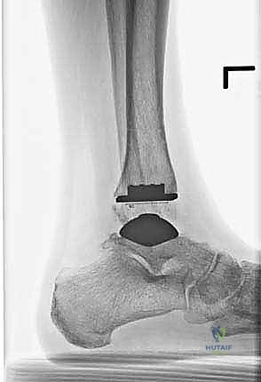
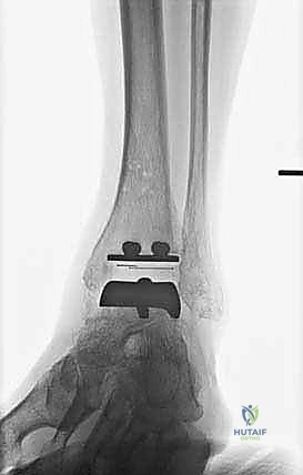
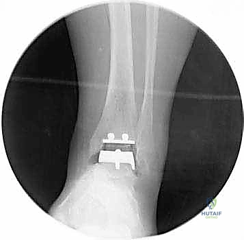
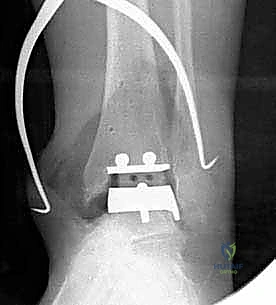
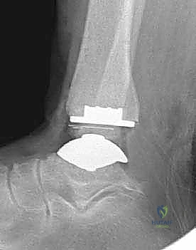
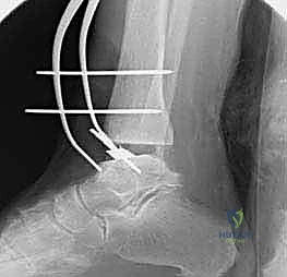
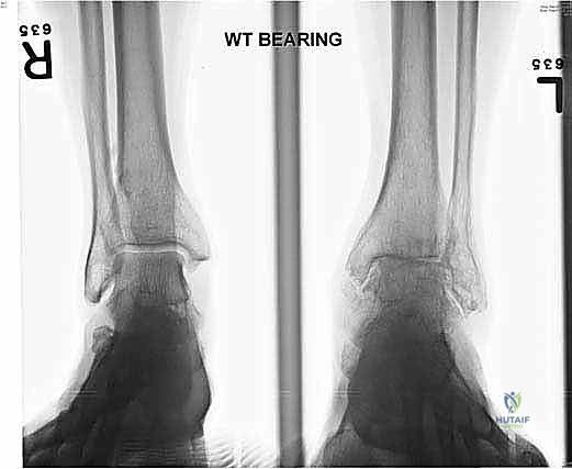
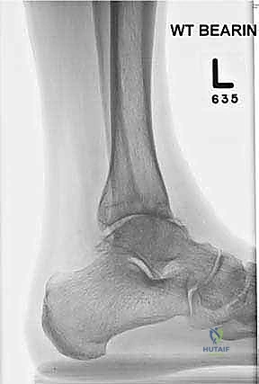
Standard imaging includes weight-bearing anteroposterior (AP), lateral, and mortise radiographs of the ankle, as well as weight-bearing views of the foot. We assess the coronal alignment (varus/valgus talar tilt), the sagittal alignment (anterior/posterior translation of the talus), and the presence of osteophytes that may block motion.
For any patient with a complex deformity or questionable bone stock, a non-contrast CT scan is mandatory. The CT allows us to map the exact location and volume of subchondral cysts and accurately assess the rotational profile of the syndesmosis. If avascular necrosis (AVN) of the talus is suspected, an MRI is obtained to quantify the extent of the necrotic segment, as greater than 50% involvement typically precludes resurfacing arthroplasty.
Surgical Templating and Deformity Correction Strategy
Digital templating is an indispensable step. Using calibrated radiographs, we estimate the required sizes for the tibial and talar components. The goal is to maximize cortical coverage on the tibial plafond without overhanging and impinging on the syndesmosis or the medial malleolus. For the talus, we template to restore the center of rotation and ensure adequate AP coverage. We must also plan our deformity correction strategy. If the patient has a correctable varus deformity, we anticipate performing a lateral ligament reconstruction and potentially a medial deltoid release. If the deformity is driven by extra-articular pathology, such as a varus calcaneus, we will template for a concomitant Dwyer or lateralizing calcaneal osteotomy to ensure the mechanical axis passes squarely through the center of our implanted prosthesis.
Anesthesia, Tourniquet, and Patient Positioning
Optimal patient positioning and anesthesia are foundational to a smooth procedure. We routinely employ a continuous popliteal sciatic nerve block combined with a saphenous nerve block. This provides profound intraoperative anesthesia and excellent postoperative analgesia while preserving proximal quadriceps function, facilitating early mobilization. Because we utilize a proximal thigh tourniquet to ensure a bloodless field, general anesthesia or a supplemental femoral nerve block is required for patient comfort.
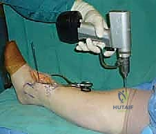
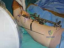
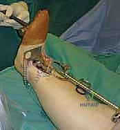
The patient is positioned supine on a radiolucent operating table. A critical maneuver is positioning the patient such that the plantar aspect of the operative foot rests exactly at the distal edge of the table. This allows the surgeon to freely dorsiflex and plantarflex the ankle throughout the procedure, a motion essential for inserting cutting guides and the final implants. A substantial bump is placed beneath the ipsilateral hip to internally rotate the leg, neutralizing the natural external rotation of the lower extremity and bringing the ankle mortise into a true AP orientation pointing directly toward the ceiling. The limb is prepped and draped in a standard sterile fashion, ensuring the iliac crest is accessible should autologous structural bone graft be required.
Step-by-Step Surgical Approach and Fixation Technique
Alright, the patient is prepped, the tourniquet is inflated, and we are ready to commence. The anterior approach to the ankle is our workhorse; it provides unparalleled exposure to the tibiotalar joint but demands absolute respect for the soft tissue envelope.
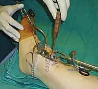
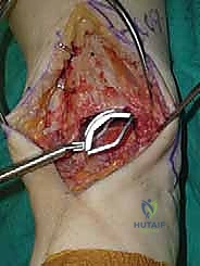
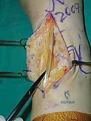
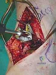
The Anterior Incision and Superficial Dissection
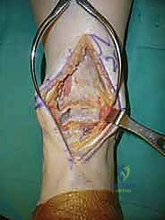
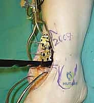
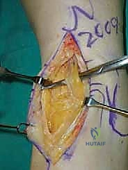
We utilize a longitudinal, midline anterior incision. I typically start approximately 10 to 12 centimeters proximal to the tibiotalar joint line, positioned roughly 1 centimeter lateral to the palpable crest of the tibia. This proximal extension is not superfluous; it is absolutely necessary to accommodate the extramedullary tibial alignment guides. The incision is carried distally, crossing the joint line, and terminating just distal to the talonavicular joint.
As we incise the skin and subcutaneous tissue, we must maintain a strict full-thickness dissection. Skiving or creating thin skin flaps is a recipe for devastating marginal necrosis and subsequent deep infection. We immediately identify the superficial peroneal nerve (SPN), particularly its medial dorsal cutaneous branch, which frequently crosses our surgical field from lateral to medial near the joint line. Once identified, it is gently mobilized and retracted laterally with the skin flap.
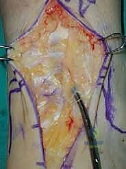
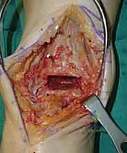
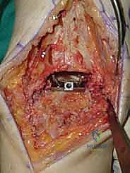
Deep Dissection and Arthrotomy
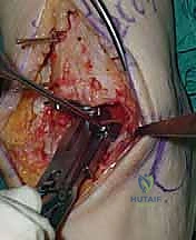
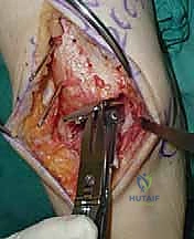
We now encounter the extensor retinaculum. We identify the extensor hallucis longus (EHL) tendon and sharply incise the retinaculum directly over it.
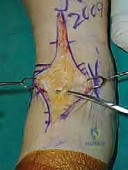
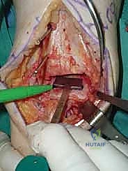
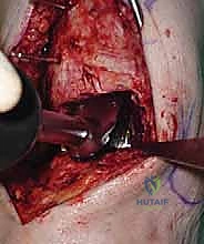
By staying within the EHL sheath, we create a robust layer for later closure and prevent bowstringing of the tendons. We develop the interval between the tibialis anterior (TA) medially and the EHL laterally. Deep to these tendons lies the critical neurovascular bundle: the anterior tibial artery and the deep peroneal nerve. Using blunt dissection, we mobilize this bundle as a single unit and retract it laterally alongside the EHL and extensor digitorum longus (EDL).
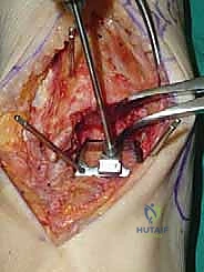
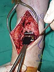
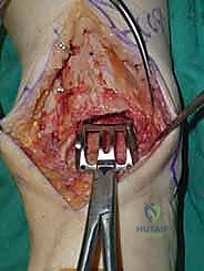
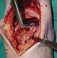
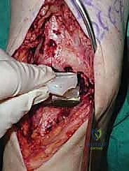
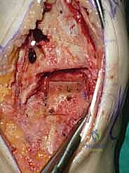
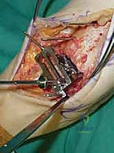
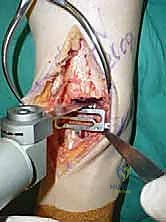
We then perform a longitudinal capsulotomy to expose the tibiotalar joint. At this stage, the joint is often obscured by massive anterior tibial and talar osteophytes. Using a rongeur and a small oscillating saw, we aggressively resect these osteophytes. This is not merely for visualization; removing this bony impingement is essential to restore dorsiflexion and accurately identify the true anatomic joint line and the medial and lateral gutters. We insert a toothless lamina spreader into the joint to distract the mortise, taking great care not to crush the articular cartilage of the talus that we intend to preserve as our reference point.
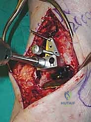
Tibial and Talar Preparation and Bone Resection
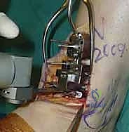
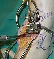
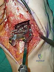
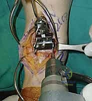
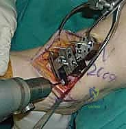
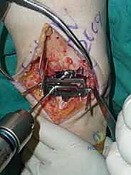
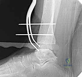
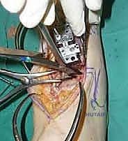
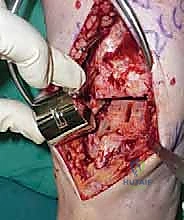
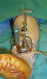
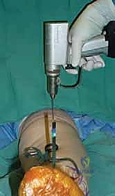
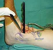
The precision of our bone cuts dictates the survivorship of the STAR implant. We begin by applying the extramedullary tibial alignment guide, securing it proximally to the tibial tubercle and distally to the distal tibia. The guide is adjusted to ensure the cutting block is perfectly parallel to the mechanical axis of the tibia in the coronal plane, and recreates the native posterior slope (typically 3 to 4 degrees) in the sagittal plane.
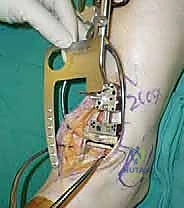
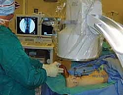
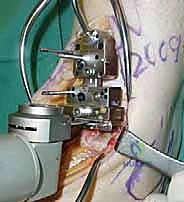
We pin the cutting block in place and verify our alignment with intraoperative fluoroscopy. The tibial resection must be conservative; we aim to remove only 3 to 4 millimeters of bone from the deepest part of the plafond, preserving the dense subchondral bone plate which provides critical structural support for the tibial tray. Using a narrow oscillating saw, we make the tibial cut, ensuring we do not notch the medial malleolus or violate the lateral syndesmosis.
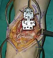
Following the tibial resection, we address the talus. The STAR technique utilizes a referencing guide based off the cut tibial surface to ensure perfectly parallel cuts. The talar resection involves a series of chamfer cuts to accommodate the complex geometry of the talar component. We place the talar cutting block, ensuring it is centered mediolaterally to prevent medial or lateral gutter impingement.
The cuts are executed meticulously. We then utilize a specialized rasp to smooth the bony surfaces, ensuring intimate contact between the host bone and the titanium porous coating of the implants. Any residual osteophytes in the medial or lateral gutters, or the posterior capsule, are aggressively debrided at this stage using an angled curette or pituitary rongeur.
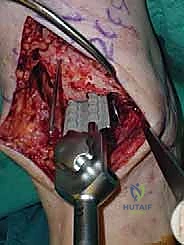
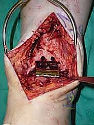
Trialing, Soft Tissue Balancing, and Final Implantation
With the bone beds prepared, we insert the trial components. The STAR is a mobile-bearing device, meaning a polyethylene meniscus glides freely between the fixed tibial and talar metallic components. We insert the appropriate thickness trial meniscus and run the ankle through a full range of active and passive motion. We are assessing three critical parameters: stability, impingement, and tracking. The joint should be stable to varus/valgus stress; if it opens asymmetrically, we must perform targeted ligamentous releases (e.g., deep deltoid release for tight medial structures) or plications. We check for any bony impingement in the gutters that might restrict motion or cause pain. Finally, the trial meniscus should track centrally without spinning out or edge-loading during flexion and extension.
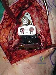
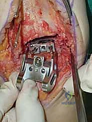
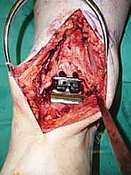
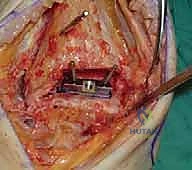
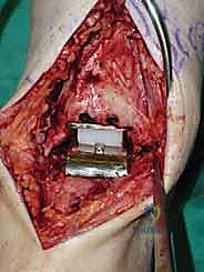
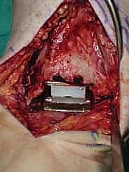
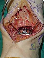
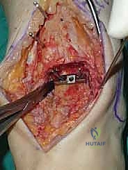
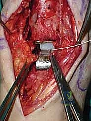
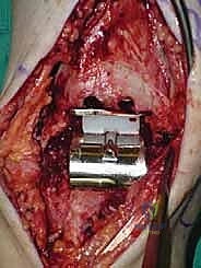
Once we are satisfied with the trial, we proceed to final implantation. The native bone is thoroughly irrigated and dried to remove marrow fat and debris. The definitive uncemented titanium tibial tray is impacted into place, ensuring it sits flush against the cut tibial surface without gaps.
Next, the talar component is impacted onto the prepared talar dome. Finally, the definitive highly cross-linked polyethylene bearing of the predetermined thickness is inserted.
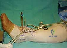
We perform a final fluoroscopic check to confirm optimal seating and alignment. The tourniquet is deflated, and meticulous hemostasis is achieved. The extensor retinaculum is securely repaired over the EHL tendon using interrupted absorbable sutures. The subcutaneous tissue and skin are closed in a layered, tension-free manner. A sterile compressive dressing and a well-padded short-leg splint in neutral dorsiflexion are applied.
Complications, Incidence Rates, and Salvage Management
Total ankle arthroplasty is a technically demanding procedure with a steep learning curve. Complications, when they occur, can be limb-threatening and require complex salvage reconstructive techniques. We broadly categorize complications into intraoperative, early postoperative, and late postoperative events.
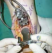
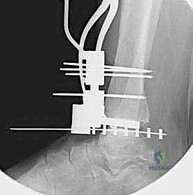
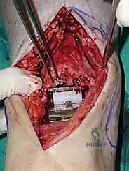
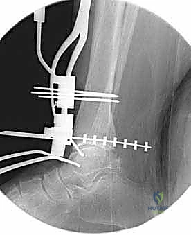
Intraoperatively, the most common complication is a fracture of the medial or lateral malleolus, occurring in up to 5-10% of cases, often due to aggressive saw blade excursion or over-distraction. These must be recognized immediately and fixed with standard AO techniques (e.g., tension band wiring or lag screws) to prevent postoperative instability. Early postoperative complications are dominated by wound healing issues. The anterior skin envelope of the ankle is notoriously tenuous. Marginal skin necrosis or superficial dehiscence occurs in approximately 10% of patients and requires aggressive local wound care; deep infection, though rare (<2%), is catastrophic and typically mandates implant explantation, placement of an antibiotic spacer, and eventual conversion to a tibiotalocalcaneal (TTC) arthrodesis.
Late complications are primarily mechanical. Aseptic loosening and subsidence, particularly of the talar component, can occur due to inadequate initial fixation, poor bone stock, or abnormal biomechanical stresses from uncorrected deformities. Gutter impingement, where heterotopic ossification or residual osteophytes cause pain and restrict motion, is a known complication of the STAR prosthesis, sometimes requiring arthroscopic or open debridement. Polyethylene wear and subsequent osteolysis, while mitigated by modern highly cross-linked polyethylenes, remain a long-term concern.
| Complication Type | Estimated Incidence | Prevention & Intraoperative Management | Definitive Salvage / Treatment |
|---|---|---|---|
| Intraoperative Malleolar Fracture | 5 - 10% | Meticulous saw control; avoid over-distraction with lamina spreaders; direct visualization of blade tip. | Immediate internal fixation (screws/tension band); prolonged postoperative immobilization. |
| Wound Dehiscence / Necrosis | 8 - 12% | Full-thickness flaps; minimal skin retraction; avoid tourniquet times > 120 mins; strict elevation post-op. | Local wound care; negative pressure wound therapy; rotational or free tissue transfer for exposed hardware. |
| Deep Periprosthetic Infection | 1 - 2% | Preoperative optimization (HbA1c, smoking cessation); meticulous sterile technique; appropriate prophylactic antibiotics. | Two-stage revision: Explantation, aggressive debridement, antibiotic spacer, followed by TTC fusion with structural graft. |
| Aseptic Loosening / Subsidence | 5 - 8% (at 10 yrs) | Preserve subchondral bone; ensure orthogonal cuts; correct coronal/sagittal deformities to prevent edge-loading. | Revision arthroplasty (if bone stock allows) or conversion to TTC arthrodesis with massive bulk allograft/autograft. |
| Gutter Impingement | 10 - 15% | Aggressive intraoperative debridement of medial/lateral gutters and posterior capsule; appropriate component sizing. | Arthroscopic or open gutter debridement and synovectomy; removal of heterotopic ossification. |
Phased Post-Operative Rehabilitation Protocols
The surgical procedure is only half the battle; a rigorous, phased postoperative rehabilitation protocol is paramount to achieving a functional, pain-free total ankle arthroplasty. Our protocol is designed to protect the uncemented bony ingrowth phase while preventing debilitating stiffness.
Phase I: Maximum Protection and Soft Tissue Healing (Weeks 0-2)
Immediately postoperatively, the patient is placed in a bulky, well-padded short-leg splint with the ankle locked in neutral dorsiflexion. The primary goals during this phase are wound healing, edema control, and pain management. The patient is strictly non-weight-bearing (NWB) on the operative extremity. They are instructed to keep the limb elevated above the level of the heart for 22 hours a day to mitigate swelling, which is the primary enemy of the anterior incision. At the two-week mark, the patient returns to the clinic for suture removal. If the wound is impeccably healed, we transition to the next phase.
Phase II: Controlled Mobilization and Early Weight-Bearing (Weeks 2-6)
At two weeks, the patient is transitioned into a removable controlled ankle motion (CAM) boot. We now initiate a progressive weight-bearing protocol. Patients begin with touch-down weight-bearing and gradually advance to full weight-bearing in the CAM boot over the next four weeks, guided by their pain tolerance. Crucially, we initiate active and active-assisted range of motion (ROM) exercises out of the boot multiple times a day. The focus is on maximizing dorsiflexion and plantarflexion; inversion and eversion are initially restricted to protect the medial and lateral soft tissue repairs. Gentle stationary cycling with low resistance
Clinical & Radiographic Imaging Archive