The BOX Total Ankle Arthroplasty: An Intraoperative Masterclass for Physiologic Motion Restoration
Key Takeaway
Join us in the OR for a deep dive into BOX Total Ankle Arthroplasty. This masterclass covers comprehensive surgical anatomy, meticulous preoperative planning, and granular, real-time intraoperative execution. We'll explore instrument use, critical pearls, potential pitfalls, and strategies for complication management, ensuring optimal restoration of physiologic ankle motion and superior patient outcomes.
Introduction to the BOX Total Ankle Arthroplasty: A Paradigm Shift in Ankle Reconstruction
Alright fellows, gather 'round. Today, we're performing a BOX Total Ankle Arthroplasty (TAA), a procedure that truly represents the cutting edge in restoring physiologic motion to arthritic ankles. For too long, ankle arthrodesis was considered the gold standard, but as you know, it comes with significant drawbacks: high rates of nonunion, secondary degenerative changes in adjacent joints, and a profound loss of motion that severely impacts ambulation, especially in patients with multi-joint involvement. The BOX system, born from extensive research into ankle kinematics, offers a compelling alternative designed to replicate the natural rolling and sliding motion of the talus within the mortise, guided by the preserved ligamentous apparatus.
Understanding the BOX Philosophy
The core principle of the BOX prosthesis lies in its unique three-component articulating geometry. This design is engineered to be entirely compatible with the isometric fibers of the calcaneofibular and tibiocalcaneal ligaments, allowing them to continue guiding natural ankle motion. Unlike earlier designs, the BOX system aims for full congruence across the articulating surfaces throughout the entire range of motion, which we believe will translate to minimized wear and improved longevity. Our technique prioritizes minimal bone resection: typically 4 mm from the talus and 5 to 10 mm from the tibia. Crucially, we utilize a sophisticated joint tensioning device before making the tibial cuts, ensuring that ligament balance and tension are precisely accounted for and the meniscal implant thickness is set to achieve this ideal state.
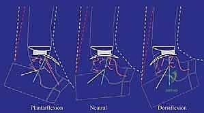
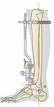
FIG 1 • The kinematics of the replaced ankle in the sagittal plane when guided by a computerized model of the four-bar linkage mechanism.
Observe this kinematic model, fellows. You can see how the BOX Ankle's components interact. In dorsiflexion, the meniscal bearing moves forward on the tibial component; in plantarflexion, it moves backward. This characteristic motion confirms the restoration of physiologic kinematics, a hallmark of the BOX system.
Indications and Contraindications: Patient Selection is Paramount
Selecting the right patient is the first step toward a successful outcome.
Indications for BOX Total Ankle Arthroplasty
- Primary or Post-traumatic Tibiotalar Arthrosis: This is our most common indication.
- Low Functional Demand: While the BOX system aims for physiologic motion, patients with exceptionally high-impact demands might still be better suited for other options.
- Patients Over 50 Years of Age: Generally, older patients with lower functional demands tend to fare better with TAA.
- Rheumatoid Arthritis: All patients with rheumatoid arthritis involving the tibiotalar joint are typically good candidates.
- Refusal of Arthrodesis: For patients who understand the risks and benefits and refuse fusion, TAA can be a viable option, provided no absolute contraindications exist.
Absolute Contraindications
- Severe Morphologic Defects of the Ankle: Significant bone loss or severe deformities that cannot be adequately corrected.
- Significant Osteoporosis or Osteonecrosis: Particularly affecting the talus, as this compromises implant fixation and stability.
- Prior or Active Infections of the Foot and Ankle: A history of infection requires meticulous workup and often a staged approach if TAA is to be considered at all. Active infection is an absolute contraindication.
- Vascular Insufficiency or Severe Neurologic Deficits: Conditions like motor dysfunction, spasticity, or severe neuropathy can compromise healing, lead to recurrent issues, or make rehabilitation impossible.
Relative Contraindications (Potentially Resolvable)
- Capsuloligamentous Instability: If this cannot be appropriately balanced during surgery, it can lead to implant failure. We must address and balance any instability intraoperatively.
- Uncorrectable Foot Deformity: The ankle joint needs a stable, plantigrade platform. If we cannot achieve a corrected, plantigrade foot position, TAA will fail. This requires careful preoperative assessment and potentially concomitant foot reconstruction.
- Severe Ipsilateral Hip and Knee Deformities or Malalignment, or Previous Arthrodesis at These Joints: While challenging, these can sometimes be addressed. However, they significantly complicate rehabilitation and may alter loading mechanics, potentially impacting TAA longevity.
Preoperative Planning: Precision Before Incision
Fellows, effective preoperative planning is non-negotiable. It dictates our success.
Radiographic Assessment
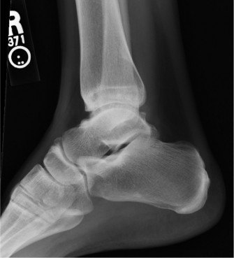
We require AP and mediolateral ankle radiographs, taken with the patient in double leg support (fully weight-bearing). This is crucial for assessing the true preoperative alignment and deformity under physiological loading.
- Magnification Assessment: Always assess radiographic magnification. We use a radiographic scaling technique or compare a known measurement (e.g., foot length, ankle width) to the radiograph. The BOX prosthesis provides templates from 100% to 120% in 5% intervals to compensate for these discrepancies.
- Component Sizing:
- Tibial Component: Assess the AP length at the level of planned resection and the mediolateral fit between the malleoli.
- Talar Component: Assess the AP fit.
- Meniscal Implant: The meniscal implant size and color code correspond directly to the talar implant.
- Matching Implants: We recommend matching tibial and talar implants within one size up or down (e.g., small tibia with medium talar, or large tibia with medium talar). Avoid significant mismatches like a small tibia with a large talar implant, as this can lead to instability or impingement.
- Joint Line Marking: With the ankle positioned in maximum dorsiflexion, mark the most anterior borders of the articulating surfaces. Also, mark the central mediolateral line. This central line is vital for correctly positioning the tibial alignment guide later, ensuring optimal mediolateral support.
Surgical Anatomy: Navigating Critical Structures
Before we make our incision, let's review the critical anatomy we'll encounter.
- Neurovascular Structures:
- Superficial Peroneal Nerve: This nerve, a branch of the common peroneal nerve, runs subcutaneously over the anterolateral aspect of the leg and foot. It provides sensation to the dorsum of the foot. It is highly susceptible to injury during skin incision and subcutaneous dissection. We must identify and protect it meticulously.
- Deep Neurovascular Bundle: Comprising the deep peroneal nerve, anterior tibial artery, and venae comitantes, this bundle lies deep to the extensor retinaculum, between the tibialis anterior and extensor hallucis longus tendons. It's at risk during distal soft tissue elevation and capsular dissection, especially when identifying the talar head and neck.
- Muscular Intervals: Our approach utilizes the interval between the peroneus tertius tendon and the extensor digitorum communis tendons. The peroneus tertius is typically lateral to the extensor digitorum communis. Identifying these tendons precisely allows for a safe passage to the joint capsule.
- Osteology: We'll be working on the distal tibia and the talus. Understanding the morphology of the malleoli is paramount to avoid iatrogenic fracture during bone resection and implant insertion. The anterior prominence and exostoses of the distal tibia often need trimming for adequate joint access.
- Ligamentous Apparatus: The preserved calcaneofibular and tibiocalcaneal ligaments are essential for the BOX system's function. We must avoid violating their integrity unnecessarily during our approach and soft tissue releases.
Patient Positioning and Surgical Approach
Alright team, let's get our patient positioned and prepped.
Patient Positioning
The patient is positioned supine on the operating table. Ensure adequate padding at pressure points.
Tourniquet Application and Sterilization
We will apply a tourniquet to the upper third of the thigh. Before inflation, the foot and ankle are thoroughly exsanguinated with an Esmarch elastic wrap. The entire leg, up to the knee, must be prepped and draped in a sterile fashion.
The Anterolateral Approach
-
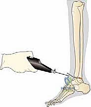
Skin Incision: I will make an anterolateral skin incision, approximately 8 to 10 cm long. It's crucial to leave one-third of the incision distal to the joint line and two-thirds proximal. This allows for excellent exposure while minimizing tension on the distal skin flap.
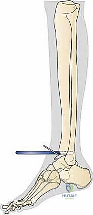
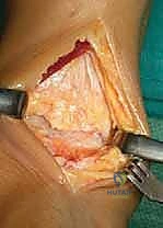
FIG 2A • Anterolateral skin incision.
-
Subcutaneous Dissection and Nerve Protection: Carefully incise the subcutaneous tissue. Identify and meticulously protect the superficial peroneal nerve. This nerve often branches and can be quite superficial. Use gentle blunt dissection and careful retraction to keep it out of harm's way.
SURGICAL WARNING: The superficial peroneal nerve is highly vulnerable during this stage. Inadequate protection can lead to painful neuromas or sensory deficits. Always prioritize its identification and gentle retraction.
-
Retinacular and Tendon Identification: The superior and inferior extensor retinacula are incised. Next, identify the peroneus tertius tendon. We will continue our incision between the peroneus tertius and the extensor digitorum communis tendons. This interval provides a safe window to the joint.
-
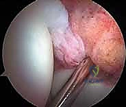
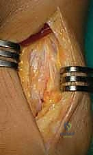
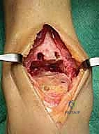
Capsulotomy and Soft Tissue Elevation: A longitudinal capsulotomy is now performed to expose the ankle joint.
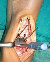
FIG 2B • Longitudinal capsulotomy to expose the ankle joint.
Carefully elevate the capsule and soft tissues medially and laterally to the malleoli. Insert retractors *deep* to the soft tissues and directly onto the malleoli. This deep retraction is key to avoiding potentially harmful direct skin tension.

> **SURGICAL WARNING:** Excessive skin tension from superficial retraction can compromise wound healing and lead to dehiscence. Always retract deeply on bone.
- Debridement and Exposure: It is imperative to fully expose the medial and lateral aspects of the tibiotalar joint. All fibrous tissue and osteophytes, which often limit motion and obscure anatomical landmarks, must be meticulously removed. This typically requires soft tissue elevation on the distal anterior tibia, immediately proximal to the ankle joint, to permit satisfactory positioning of the tibial alignment guide. Distally, our incision and capsular-soft tissue elevation must extend to identify the transition between the head and neck of the talus, all while protecting the deep neurovascular bundle.
Intraoperative Execution: The BOX Implant Technique
Now, let's move into the precise steps of implanting the BOX prosthesis. Pay close attention to the sequence and instrument specificities.
Initial Tibial Preparation
-
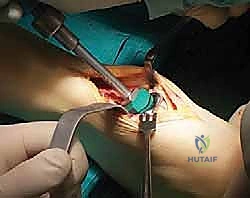
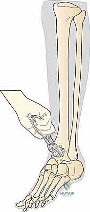
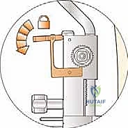
Anterior Tibial Exostosis Resection: First, we need to gain clear access to the joint space. Use a chisel to trim any anterior prominence and exostosis from the distal tibia. This often involves removing a significant amount of anterior spurring that limits dorsiflexion.
TECH FIG 1 • Trimming the anterior prominence and exostosis of the distal tibia using a chisel.
-
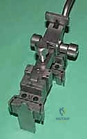
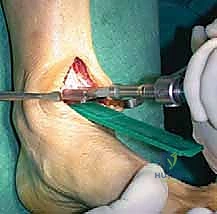
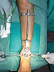
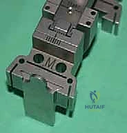
Assemble the Tibial Alignment Guide: Take the tibial alignment guide and assemble it with the proximal clamp and connector. Tighten this assembly with the proximal screw. Next, insert the talar cutting block onto the tibial alignment guide and secure it with the frontal screw.
TECH FIG 2A • Talar cutting block onto the tibia alignment guide, with the ratchet to the START position.
-
Ratchet Adjustment: With the button in the unlocked position and depressed, adjust the ratchet mechanism to the START position. This is the baseline. Once set, lock the ratchet to prevent any unwanted movement during subsequent positioning and sawing.
-
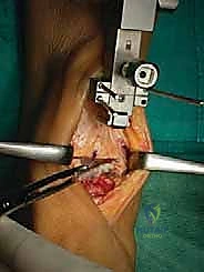
Initial Guide Placement: Now, carefully place the assembled guide onto the lower leg. The posterior tongue of the talar cutting block should be inserted into the joint space, ensuring it is precisely centered between the malleoli.
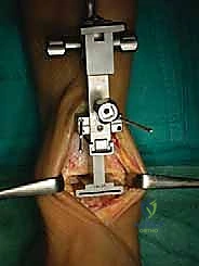
TECH FIG 2 • Placement of assembled guide for talar cut.
-
Proximal Clamp Placement: Position the proximal clamp firmly at the proximal tibial tuberosity. This provides a stable proximal anchor for our alignment.
TECH FIG 2B • Tibia alignment guide assembled onto the shank.
-
Tibial Cutting Block Insertion: Select the appropriate size of tibial cutting block based on your preoperative templating. Insert this block onto the tibial alignment guide in a neutral mediolateral adjustment (center of the scale).
-
Spring Fastening: Fasten the spring around the proximal shank of the alignment guide. This helps maintain stability.
-
Alignment of the Guide: This is a critical step. Align the shaft of the tibial alignment guide parallel with the longitudinal axis of the tibia. This must be checked in both the anterior and lateral views by adjusting the proximal clamp.
SURGICAL PEARL: A common and dangerous error here is to align the shaft parallel to the front of the tibia rather than its true longitudinal axis. This will inevitably result in an erroneous posterior inclination of the tibial component, leading to altered kinematics and potential early failure. Take your time, use anatomical landmarks and fluoroscopy if available, to ensure true longitudinal alignment.
-
Mediolateral Adjustment of Tibial Cutting Block: Assess the central position of the block relative to the malleoli. If adjustment is needed, move the tibial cutting block slightly forward (as if to remove it) until it is free to slide mediolaterally. Reinsert the block in the desired medial or lateral adjustment, then tighten it with the frontal screw.
-
Pinning the Talar Cutting Block: Recheck that the tongue of the talar cutting block remains centered between the malleoli. Now, pin the talar cutting block using two or three of the four diagonally opposite pin positions. Observe how the pins converge toward the center of the tibial shaft, providing robust fixation.
Horizontal Talar Cut
-
Locking the Tongue Position: Lock the position of the tongue of the talar cutting block as far as it will go into the joint space with the frontal screw. This ensures maximum stability for the cut.
-
Foot Position for Talar Cut: Ensure the foot is in the neutral flexion position. This means 0 degrees dorsiflexion and plantarflexion, with a 90-degree angle between the tibia axis and the plantar aspect of the foot.
SURGICAL WARNING: If the foot is in dorsiflexion or plantarflexion during this cut, a malrotation of the talar component will result, severely restricting the final range of motion of the implanted prosthesis. Confirm neutral position meticulously.
-
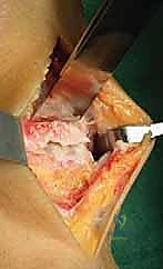
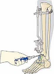
Perform the Horizontal Talar Cut: With the guide securely pinned and the foot in neutral, carefully complete the horizontal talar cut using an oscillating saw. Ensure your saw blade remains flush against the cutting block.
-
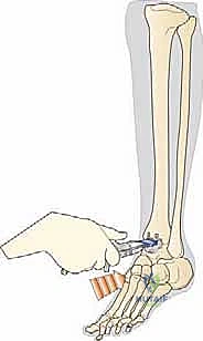
Remove Talar Block and Resect Bone: Once the cut is complete, remove the talar block. Now, carefully remove the resected talar bone.
TECH FIG 3 • Removal of the talar bone stock.
Use a **chisel** (small 30 mm, medium 35 mm, large 40 mm long, corresponding to implant sizes) to fragment and remove the cut section of bone.

> **SURGICAL PEARL:** Fragmenting these thin sections of bone requires considerable care and patience. The bone is often thicker posteriorly and can be retained by the posterior periosteum and capsule. Be extremely careful not to lean against the malleoli with the chisel, as this may result in their fracture, a significant and avoidable complication. Work slowly and methodically.
Tibial Implant Sizing and Tensioning
-
Measure Tibial Cut Length: Before removing the entire tibial alignment guide assembly, use the tibial length gauge to measure the AP length of the horizontal tibial cut. This measurement is crucial for determining the appropriate size of the tibial implant (small 30 mm, medium 35 mm, and large 40 mm).
SURGICAL PEARL: If your measurement falls between two sizes, always size down to prevent overhang of the tibial component, which can lead to soft tissue irritation and impingement.
-
Adjusting Tibial Implant Size (If Needed): In some cases, you might decide to increase the tibial implant size. If this is necessary, you must:
- Select the next biggest tibia cutting block.
- Increase the depth of the 4.5-mm holes using the next larger drill.
- Redrill the two 3.2-mm drill holes.
- Recut the side cuts and extend the top horizontal cut to meet the small holes.
- Only then should you remove the complete tibial cutting guide assembly.
SURGICAL WARNING: When increasing the tibia implant size, it is absolutely critical to increase the depth of the 4.5-mm holes. Failure to do so may result in fracture of the posterior portion of the tibia during subsequent steps or implant impaction.
-
Joint Tensioning with the Ratchet:
- Assemble the knob tightener into the large blue handle and unlock the ratchet button.
- Insert the knob tightener into the ratchet knob and turn it in a counterclockwise direction.
TECH FIG 5 • The ratchet applies tension to the joint via the tibial tensioner by turning the ratchet knob in a counterclockwise direction.
<figure class="operative-step-slider my-4 text-center p-3 border rounded shadow-sm bg-light">
TECH FIG 5 • At the end, the ratchet button is locked again.
The amount of tension applied here will represent the initial tension in the replaced joint, provided the meniscal implant you plan to use matches the tibial tensioner used.

> **SURGICAL PEARL:** We always recommend tensioning the joint and using a meniscal implant that is as thin as possible. This prevents excessive or unnecessary bone removal from the tibia, preserving precious bone stock.

*   **Adjusting Tibial Cut Level:** If, after initial tensioning, you feel the selected position of the horizontal cut on the tibia is too distal (meaning too little tibial bone is being removed), you can adjust. Go back to the ratchet START position, insert a thicker **6-mm or 7-mm tibial tensioner** into the tibial cutting block, and apply tension again.
*   **Lock the Ratchet:** Once the desired tension and level of tibial cut are achieved, lock the ratchet. At this point, the position of the cuts on the tibia is precisely set to match the combined thickness of the implant components.
Final Tibial Bone Resection and Preparation
-
Tibial Cuts: Using your oscillating saw, complete the three tibial cuts. Exercise extreme caution to avoid notching the malleoli with the saw blade. Maintain a steady hand and ensure the blade stays within the confines of the cutting block.
-
Drilling 3.2-mm Holes: Select the tibial corner drill. Drill the two 3.2-mm holes up to the depth mark (S, M, or L, corresponding to your chosen implant size).
SURGICAL WARNING: Take care not to drill too far beyond the depth mark, as this can compromise cortical integrity.
-
Drilling 4.5-mm Holes: Select the appropriate 4.5-mm tibia drill (S, M, or L) to suit the tibial block you are using. Drill the two 4.5-mm holes in the tibia through the tibial cutting block up to the depth stop.
-
Remove Tibial Cutting Block: Release the frontal screw and carefully remove the tibial cutting block.
-
Joining the Corner Cuts: Assemble the tibial corner gouge into the large blue instrument handle. Use this gouge to join the three cuts in the two corners of the tibial resection. This creates the precise shape for the tibial component.

TECH FIG 6 • When the holes are drilled and the cuts are completed at the tibia, the tibial corner gouge is used to join the three cuts in the two corners.
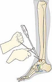
-
Joining the Keyhole Cuts: Use the tibial keyhole cutter, assembled in the slide hammer, to join the two 4.5-mm holes to the horizontal tibial cut.
SURGICAL WARNING: Care should be taken not to break out the holes by biasing the cutter proximally or distally. Maintain a centered, controlled motion.
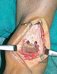
-
Tibial Preparation Complete: At this point, the tibial preparation is complete.
TECH FIG 7 • The tibial preparation is now complete.
Talar Preparation (Continuing from Original Text)
The next step, not detailed in the provided text but implied by the flow, would be the talar chamfer cuts and subsequent talar component trial. Let's imagine we're moving onto that.
-
Placement of Talar Chamfer Guide: We will now place the talar chamfer guide. This guide is crucial for making the precise cuts on the talus that will accommodate the talar component. It's typically held by a small blue handle in front.
TECH FIG 8 • Placement of talar chamfer guide by the small blue handle in front.
<figure class="operative-step-slider my-4 text-center p-3 border rounded shadow-sm bg-light">
TECH FIG 8 • Placement of talar chamfer guide by the small blue handle in front.
The guide ensures the correct angles and depth for the chamfer cuts, which are essential for the congruency and stability of the talar implant. Pin this guide securely.
-
Performing Talar Chamfer Cuts: Using an oscillating saw, make the anterior and posterior chamfer cuts on the talus through the guide slots. Again, precision is key.
-
Drilling Talar Peg Holes: After the chamfer cuts, drill the necessary peg holes into the talus through the guide. These holes will accept the fixation pegs of the talar component. Ensure appropriate depth.
-
Talar Preparation Complete: Remove the talar chamfer guide and any remaining bone fragments. The talar bed is now prepared.
Trial Implants and Final Sizing
-
Insert Tibial Trial: Using the tibial inserter (in the large blue handle) and the green profile spacer, insert the selected size of tibial trial firmly against the cut bone surface. The green profile spacer helps ensure the trial is seated hard against the resected tibia.
TECH FIG 9 • Insertion of tibial trial using the tibial inserter and green profile spacer.
-
Insert Talar Trial: Now, place the corresponding talar trial onto the prepared talar bone bed.
-
Insert Meniscal Trial: Finally, insert a meniscal trial that is one size thicker than your planned final meniscal implant. This slightly thicker trial allows for a more robust assessment of joint tension and stability.
TECH FIG 10A • Insertion of the meniscal trial.
<figure class="operative-step-slider my-4 text-center p-3 border rounded shadow-sm bg-light">
TECH FIG 10B • Assessing joint stability with the meniscal trial.
-
Assess Range of Motion and Stability: With the trials in place, meticulously assess the ankle's range of motion (dorsiflexion and plantarflexion) and stability throughout the arc. Check for any impingement, excessive laxity, or tightness. The goal is a well-balanced, stable joint with good motion. If there's any concern, adjust the meniscal trial thickness (up or down) until optimal tension and motion are achieved. Remember, the final meniscal implant will be one size thinner than the trial that gives you the ideal tension.
SURGICAL PEARL: This trial phase is your last chance to fine-tune your bone resections and component sizing. Do not rush it. A perfectly balanced joint at this stage translates to a durable, functional arthroplasty.
-
Final Component Implantation: Once satisfied with the trial, remove all trial components. Prepare the bone surfaces for cementation (if using cemented components) or press-fit insertion. Meticulously clean the joint of any debris.
- Talar Component Implantation: Impact the definitive talar component onto the prepared talus. Ensure it is fully seated and stable.
- Tibial Component Implantation: Impact the definitive tibial component onto the prepared tibia. Verify its alignment and seating.
- Meniscal Bearing Insertion: Carefully insert the final meniscal bearing between the tibial and talar components. Ensure it is oriented correctly and seats smoothly.
TECH FIG 11A • Insertion of the definitive talar component.
<figure class="operative-step-slider my-4 text-center p-3 border rounded shadow-sm bg-light">
<a href="/media/hutaif_opertive/hutaif-ch70-the-box-total-a-p4092-d9c56
Additional Intraoperative Imaging & Surgical Steps

REFERENCES
-
Affatato S, Taddei P, Leardini A, et al. Wear behaviour in total ankle replacement: a comparison between an in vitro simulation and retrieved prostheses. Clin Biomech 2009;24:661–669.
-
Anderson T, Montgomery F, Carlsson A. Uncemented STAR total ankle prostheses: three to eight-year follow-up of fifty-one consecutive ankles. J Bone Joint Surg Am 2003;85A:1321–1329.
-
Bauer G, Kinzl L. Arthrodesis of the ankle joint. Orthopade 1996;25:158–165.
-
Bauer G, Eberhardt O, Rosenbaum D, et al. Total ankle replacement: review and critical analysis of the current status. Foot Ankle Surg 1996;2:119–126.
-
Buechel FF Sr, Buechel FF Jr, Pappas MJ. Ten-year evaluation of cementless Buechel-Pappas meniscal-bearing total ankle replacement. Foot Ankle Int 2003;24:462–472.
-
Chou LB, Coughlin MT, Hansen S Jr, et al. Osteoarthritis of the ankle: the role of arthroplasty. J Am Acad Orthop Surg 2008; 16:249–259.
-
Cracchiolo A III, DeOrio JK. Design features of current total ankle replacements: implants and instrumentation. J Am Acad Orthop Surg 2008;16:530–540.
-
Demetriades L, Strauss E, Gallina J. Osteoarthritis of the ankle. Clin Orthop Rel Res 1998;349:28–42.
-
Deorio JK, Easley ME. Total ankle arthroplasty. AAOS Instr Course Lect 2008;57:383–413.
-
Guyer AJ, Richardson G. Current concepts review: total ankle arthroplasty. Foot Ankle Int 2008;29:256–264.
-
Intraoperatively, the components maintained complete congruence at the two articulating surfaces of the meniscal bearing over the entire motion arc, associated with considerable anterior motion in dorsiflexion and posterior motion in plantarflexion of the meniscal bearing, as predicted by the previous mathematical models.
-
A mean of 10.1 degrees of dorsiflexion and 23.5 degrees of plantarflexion were measured immediately after implantation, for a mean additional range of motion of 18.6 degrees, which was maintained at follow-up.
-
Radiographs showed good alignment and no signs of progressive radiolucency or loosening.
-
The mean AOFAS score went from 37.0 before surgery to 64.7, 73.2, 78.4, and 85.9 respectively at 3-, 6-, 12-, and 18month follow-ups.
-
One revision was performed 3 days after implantation because of a technical error; it was successful. Another revision in arthrodesis was performed at 19 months because of a wrong indication.
-
In the scoring system used, the function and range-ofmotion sections scored better than any average previous total ankle result. 24 Pain scored similarly.
-
Hintermann B, Valderrabano V, Dereymaeker G, et al. The HINTEGRA ankle: rationale and short-term results of 122 consecutive ankles. Clin Orthop Relat Res 2004;424:57–68.
-
Hurowitz EJ, Gould JS, Fleisig GS, et al. Outcome analysis of agility total ankle replacement with prior adjunctive procedures: two to six year follow-up. Foot Ankle Int 2007;28:308–312.
-
Katcherian DA. Treatment of ankle arthrosis. Clin Orthop Rel Res 1998;349:48–57.
-
Kitaoka HB, Patzer GL. Clinical results of the Mayo total ankle arthroplasty. J Bone Joint Surg Am 1996;78A:1658–1664.
-
Lachiewicz PF. Total ankle arthroplasty: indications, techniques, and results. Orthop Rev 1994;23:315–320.
-
Leardini A, Catani F, Giannini S, et al. Computer-assisted design of the sagittal shapes for a novel total ankle replacement. Med Biol Eng Comp 2001;39:168–175.
-
Leardini A, O’Connor JJ, Catani F, et al. Kinematics of the human ankle complex in passive flexion: a single degree of freedom system. J Biomech 1999;32:111–118.
-
Leardini A, O’Connor JJ, Catani F, et al. A geometric model of the human ankle joint. J Biomech 1999;32:585–591.
-
Leardini A, O’Connor JJ, Catani F, et al. The role of the passive structures in the mobility and stability of the human ankle joint: a literature review. Foot Ankle Int 2000;21:602–615.
-
Leardini A, O’Connor JJ. A model for lever-arm length calculation of the flexor and extensor muscles at the ankle. Gait Posture 2002; 15:220–229.
-
Leardini A, O’Connor JJ, Catani F, et al. Mobility of the human ankle and the design of total ankle replacement. Clin Orthop Relat Res 2004;424:39–46.
-
Rush J. Management of the rheumatoid ankle and hindfoot. Curr Orthop 1996;10:174–178.
-
Saltzman CL, McIff TE, Buckwalter JA, et al. Total ankle replacement revisited. J Orthop Sports Phys Ther 2000;30:56–67.
-
Stengel D, Bauwens K, Ekkernkamp A, et al. Efficacy of total ankle replacement with meniscal-bearing devices: a systematic review and meta-analysis. Arch Orthop Trauma Surg 2005;125:109–119.
-
Wood PL, Deakin S. Total ankle replacement: the results in 200 ankles. J Bone Joint Surg Br 2003;85B:334–341.
-
Younger A, Penner M, Wing K. Mobile-bearing total ankle arthroplasty. Foot Ankle Clin 2008;13:495–508.
You Might Also Like