Cervical Masterclass: Posterior C1-C2 Fusion with Transarticular and Articular Mass Fixation
Key Takeaway
Welcome, fellows, to an immersive masterclass on posterior C1-C2 fusion. We'll delve into comprehensive atlantoaxial anatomy, meticulous preoperative planning, and precise patient positioning. This session provides a granular, real-time walkthrough of transarticular and articular mass screw fixation, emphasizing critical intraoperative execution, neurovascular precautions, and managing potential pitfalls. Prepare to master this challenging yet rewarding procedure.
Introduction to Atlantoaxial Instability and Fusion Principles
Welcome, fellows, to the operating theater. Today, we're tackling a critical procedure: posterior C1-C2 fusion and instrumentation. This is a complex region, demanding meticulous attention to detail and a profound understanding of surgical anatomy. The atlantoaxial joint, specifically C1-C2, is unique in the spine, contributing significantly to cervical spine mobility. In a healthy spine, C1-C2 provides approximately 11.5 degrees of flexion, 10.9 degrees of extension, 6.7 degrees of lateral bending, and a remarkable 38.9 degrees of axial rotation to each side. This extensive range of motion, particularly rotation, makes it highly susceptible to instability.
Atlantoaxial instability, fellows, is a broad term encompassing various conditions that compromise the normal function of the C1-C2 joint. The consequences can range from debilitating pain to severe spinal cord dysfunction, or the imminent threat thereof. Our goal today is to restore stability and protect the neural elements.
Comprehensive Surgical Anatomy: The Atlas and Axis
Let's begin by reviewing the intricate anatomy that makes this region so challenging and fascinating.
The Atlas (C1):
Observe the bony model. The first cervical vertebra, C1, or the atlas, is truly unique. It lacks a vertebral body and a spinous process, a stark contrast to any other vertebra. Instead, it forms a ring, comprised of an anterior arch and a posterior arch, connected by two robust lateral articular masses. This ring pivots around the odontoid process of C2.

FIG 1 • A. The atlas consists of an anterior and posterior arch connected by two articular masses.
On the superior surface of the C1 posterior arch, on each side, you'll find a distinct groove. This groove is critical, as it accommodates the vertebral artery, the first cervical nerve root (the suboccipital nerve), and their associated venous complex. In a small subset of the population, this groove can be partially or completely bridged by an arch of bone, known as the ponticulus posticus, forming an arcuate foramen. This anatomical variant is crucial to recognize preoperatively, as it significantly impacts screw trajectory and increases the risk of vertebral artery injury.
The articular masses of C1 are broad and robust. Superiorly, they articulate with the occipital condyles, forming the atlanto-occipital joints. Inferiorly, they articulate with the superior articular facets of the axis (C2), forming the lateral atlantoaxial joints.
The Axis (C2):
Now, let's examine C2, the axis.
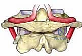
FIG 1 • C. Anterior view of the axis, demonstrating the odontoid process projecting upward from the vertebral body.
C2 is characterized by thicker laminae and a larger, often bifid spinous process compared to typical subaxial cervical vertebrae. Its most distinctive feature is the odontoid process, or dens, which projects superiorly from the vertebral body, acting as the pivot for C1 rotation. A synovial joint is located between the posterior aspect of the anterior arch of C1 and the anterior aspect of the dens.
Lateral to the odontoid process are the sloping superior articular surfaces, which articulate with the inferior articular facets of C1. The C2 pedicle is a key target for instrumentation. It can be identified in a zone between the lamina and the vertebral body, projecting superomedially. Understanding this trajectory is paramount for safe screw placement.
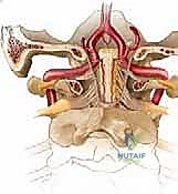
FIG 1 • D. Posterior view of the axis, demonstrating the odontoid process projecting upward from the vertebral body. The pedicle connects the lamina and the vertebral body, projecting superomedially. The pars interarticularis lies between the superior and inferior articular processes.
Ligamentous Stability:
The stability of the C1-C2 articulation relies heavily on its robust ligamentous restraints. These include:
* Transverse ligament: The primary stabilizer, preventing anterior translation of C1 on C2.
* Alar ligaments: Connect the dens to the occipital condyles, limiting axial rotation and lateral bending.
* Apical ligament: Connects the dens to the anterior rim of the foramen magnum.
* Facet capsules: Encapsulate the lateral atlantoaxial joints.
Trauma or advanced degenerative and inflammatory conditions can disrupt these critical ligamentous structures, leading to instability.
Neurovascular Structures: The Vertebral Artery and Cervical Nerves:
This is where extreme caution is warranted.
The vertebral artery is a major vessel that ascends through the foramina transversaria from C6 up to C1. After traversing the foramen transversarium at C1, it makes a sharp, critical turn. It courses medially and posteriorly, lying within the groove on the posterior arch of C1. It then passes through the posterior atlanto-occipital membrane before ascending through the foramen magnum, merging with its contralateral counterpart to form the basilar artery.
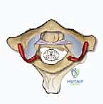
FIG 1 • E. The vertebral artery ascends through the foramina transversaria from C6 to C3. It takes a turn laterally through C2 underneath the pars interarticularis. Once it traverses the transverse foramen at C1, it turns medially and lies on the superior surface of the C1 ring. F. After passing medially on the superior surface of the C1 ring, the vertebral artery passes through the foramen magnum and merges with its counterpart to form the basilar artery.
Injury to the vertebral artery can lead to catastrophic consequences, including stroke or even death.
The C1 nerve root, or suboccipital nerve, exits cranial to the posterior arch of C1. It primarily innervates the muscles of the suboccipital triangle.
The C2 nerve root, or greater occipital nerve, exits between the posterior arches of C1 and C2, posterior to the superior C1-C2 articulation. Unlike other subaxial cervical nerve roots, it does not exit through a true foramen. It traverses inferior to the obliquus capitis inferior muscle, ascends through the semispinalis capitis, and lies superficial to the rectus capitis major. Injury to the greater occipital nerve can cause troublesome dysesthesia of the posterior scalp.
Pathogenesis and Indications for C1-C2 Fusion
Fellows, understanding the underlying pathology is paramount for appropriate surgical indication.
Causes of Atlantoaxial Instability:
* Trauma:
* Rupture of the transverse ligament (often requiring fusion).
* Odontoid fractures (especially Type II and III, particularly if displaced or non-reducible).
* Jefferson fractures (C1 ring fractures), especially if associated with transverse ligament disruption.
* Anterior atlantodental interval (AADI) greater than 3.5 mm in an adult indicates potential transverse ligament damage. An AADI > 5 mm indicates probable injury to both transverse and accessory ligaments. This is a strong indication for C1-C2 arthrodesis in a trauma setting.
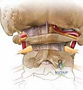
FIG 2 • A. An anterior atlantodental interval greater than 5 mm indicates likely injury to the transverse ligament and, in the setting of trauma, necessitates operative stabilization.
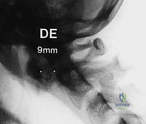
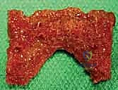
FIG 2 • B. An avulsion ( arrow ) of the transverse ligament from the ring of C1 indicates instability and may require arthrodesis of C1–2.
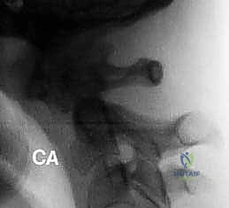
FIG 3 • A. Displaced odontoid fractures (type 2) have a higher likelihood of a nonunion and may require a primary C1–2 fusion.
* Nontraumatic Causes:
* Inflammatory Arthropathy: Rheumatoid arthritis is a classic example. Pannus or pseudo-pannus formation behind the dens can lead to cervical stenosis and myelopathy. A posterior atlantodental interval (PADI) smaller than 14 mm is associated with worse outcomes and indicates the need for decompression and fusion. The AADI is less relevant here than in trauma. Painful C1-C2 rheumatoid involvement resistant to medical therapy, or progressive subluxation with cranial settling, also indicates fusion.
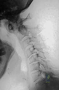
FIG 3 • C. Pseudo-pannus formation behind the dens in patients with rheumatoid arthritis can lead to cervical stenosis and myelopathy. It rarely improves without surgery, but will dissolve after C1–2 fusion.
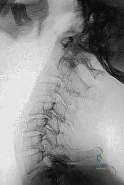
FIG 3 • E. Extension lateral radiographs demonstrate C1–2 instability in a patient with rheumatoid arthritis.
* Osteoarthritis: Primary atlantoaxial osteoarthritis can be severely painful and responds poorly to nonoperative measures. Fusion offers a high likelihood of symptom relief.
FIG 3 • B. Joint space narrowing is a sign of C1–2 osteoarthritis and responds poorly to nonoperative management.
* Congenital Anomalies: Os odontoideum, Down syndrome. If symptomatic, myelopathic, or with insufficient PADI, fusion is indicated.
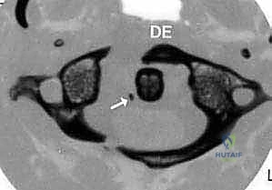
FIG 3 • F. Os odontoideum is another condition associated with instability in which part of the dens is not attached to the axis body.
* Tumor, infection, atlantoaxial rotatory subluxation (if irreducible or fixed).
Patient Evaluation: History, Physical, and Imaging
A comprehensive evaluation is non-negotiable for C1-C2 pathology.
History and Physical Examination:
* Trauma patients: Maintain a low threshold of suspicion for C1-C2 injury with blunt head/face trauma or noncontiguous spine fractures. Neurologic deficits may be present, or isolated pain.
* Rheumatoid arthritis: May present with axial neck pain, or more insidiously with deteriorating gait, bilateral hand numbness, or clumsiness, even without significant neck pain.
* Primary atlantoaxial arthritis: Often severe, unilateral neck and head pain, with marked refusal to rotate the head, especially ipsilaterally. Locking or crepitation may be audible/palpable.
* Physical Exam Key Findings:
* Active self-limited rotation: Normal rotation is up to 50 degrees to each side. C1-C2 pathology severely limits this, often due to pain.
* Palpation: Tenderness in the suboccipital area, near the C1-C2 posterior arch interval.
* Traction vs. Compression Test: (Applicable only in non-traumatic, stable settings). With the patient supine, passive lateral head rotation is assessed with slight manual traction. In C1-C2 arthritis, traction should increase motion and decrease pain, whereas axial vertex loading will cause pain and decrease rotation. Crucially, these maneuvers are contraindicated in suspected traumatic instability; the cervical spine must remain immobilized.
Imaging and Other Diagnostic Studies:
* Plain Radiographs: While a starting point, plain films, especially of the upper cervical spine, are inadequate for definitive evaluation in trauma. Sensitivity is only 52% for fractures.
* Helical CT with Sagittal and Coronal Reconstruction: This is routinely performed for diagnosis and crucial preoperative planning. It is superior to plain radiographs for detecting cervical spine fractures (98% sensitivity and specificity). While limited for pure ligamentous injury, it provides invaluable bony detail.
* MRI Scan: Essential for evaluating ligamentous integrity, spinal cord compression (e.g., from pannus), and soft tissue pathology.
* Lateral Flexion-Extension Radiographs: Used to assess dynamic instability in stable patients where ligamentous injury is suspected but not seen on static imaging. ABSOLUTELY CONTRAINDICATED in acute trauma or suspected gross instability.
* Vertebral Artery Angiogram (CT Angiogram or MRA): Highly recommended in cases of significant flexion-distraction injury, fractures extending into the transverse foramen, or facet dislocations. This is to rule out vertebral artery injury. A unilateral injury is often asymptomatic due to collateral flow, but a bilateral injury or injury in a patient with concomitant spinal cord injury can be devastating. If a vertebral artery injury is discovered, prompt anticoagulation is indicated, which must be managed carefully around surgery.
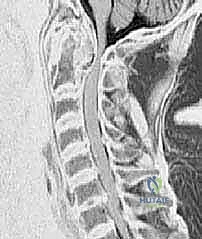
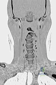
FIG 4 • Coronal reconstruction of a CT angiogram demonstrating occlusion of flow through the left vertebral artery ( right side of the image ) in a patient with a C4–5 facet fracture-subluxation.
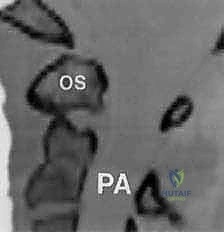
FIG 4 • Coronal reconstruction of a CT angiogram demonstrating occlusion of flow through the left vertebral artery ( right side of the image ) in a patient with a C4–5 facet fracture-subluxation.
Nonoperative Management Considerations
While our focus today is surgical, it's important to understand the role of nonoperative management.
* Hard Collar: Generally inadequate for unstable C1-C2 articulations. May be considered only for elderly, non-surgical candidates unable to tolerate more rigid immobilization.
* Halo-Vest Immobilization: A time-tested nonoperative option for certain fractures (e.g., some odontoid fractures) where reduction can be obtained and maintained. Patients are typically treated in a halo-vest for 3 months. This is a significant commitment for the patient, and surgical election to avoid it is common.
* Postoperative Halo: In some cases, a halo may be required postoperatively, depending on fixation quality, patient compliance, or other unusual circumstances.
Preoperative Planning: The Blueprint for Success
Fellows, meticulous preoperative planning is the cornerstone of a successful outcome in C1-C2 fusion.
- Review All Imaging: This includes plain radiographs, dynamic flexion-extension views (if indicated and safe), high-resolution CT scans with sagittal and coronal reconstructions, and MRI. Pay close attention to the AADI, PADI, and any evidence of spinal cord compression.
- Vertebral Artery Assessment: Scrutinize the CT angiogram or MRA for the course of the vertebral arteries, specifically looking for anatomical variants like the ponticulus posticus or aberrant loops that may compromise screw trajectories. Measure the C2 pars/pedicle dimensions and C1 lateral mass dimensions.
- Templating: Use the CT scans to template screw lengths and trajectories. For C1 lateral mass screws, aim for a bicortical purchase, typically 30-40mm. For C2 pedicle/pars screws, measure the length from the entry point to the anterior cortex of the C2 body, typically 28-36mm.
- Hardware Selection: Determine the appropriate screw diameters (usually 3.5mm or 4.0mm) and rod length. Consider whether a transarticular screw will be feasible and necessary in addition to or instead of C2 pedicle/pars screws.
- Patient-Specific Considerations: Account for patient comorbidities, bone quality (osteoporosis may necessitate cement augmentation or larger screws), and any neurological deficits.
Patient Positioning and Operating Room Setup
Now, let's get our patient ready.
- Anesthesia and Neuromonitoring: General endotracheal anesthesia is essential. We will have somatosensory evoked potentials (SSEPs) and motor evoked potentials (MEPs) monitoring throughout the case to detect any potential neurological compromise.
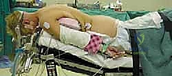
- Patient Positioning: The patient is carefully positioned prone on a radiolucent operating table.
- Chest Rolls: Place generous chest rolls longitudinally from the clavicles to the iliac crests to offload abdominal pressure, facilitate venous drainage, and minimize epidural bleeding.
- Head Support: The head is supported in a Mayfield head holder (or similar three-pin fixation device). This provides rigid immobilization and allows for precise positioning.
- Head Position: The head should be maintained in a neutral position for initial exposure. For reduction of C1-C2 subluxation, slight flexion may be required, but avoid excessive flexion which can compromise the airway or neural elements. Ensure the neck is slightly flexed to open the posterior elements of C1 and C2 for optimal access.
- Fluoroscopy Setup: The C-arm is brought in and positioned to obtain true lateral, AP, and oblique views of the C1-C2 complex. Ensure unobstructed views throughout the procedure, especially for screw placement. The lateral view is paramount for assessing screw depth and trajectory. The AP view helps verify medial/lateral trajectory.
- Prepping and Draping: The posterior cervical region, from the occiput down to at least C7, and laterally to the mastoid processes, is prepped meticulously with an antiseptic solution (e.g., chlorhexidine-alcohol) and draped in a sterile fashion. Ensure the Mayfield pins are also prepped within the field.
Step-by-Step Intraoperative Execution: The Masterclass
Alright, fellows, we are scrubbed in, and the patient is positioned. Let's begin.
1. Incision and Initial Dissection
Surgeon: "Scalpel, please. We'll make a midline incision, approximately 6-8 cm in length, centered over the C1-C2 spinous processes. Feel for the external occipital protuberance superiorly and the prominent C7 spinous process inferiorly to guide your landmarks."
- Skin Incision: Make a precise midline incision through the skin and subcutaneous tissue.
- Electrocautery: Use electrocautery to achieve hemostasis as you deepen the incision.
- Deep Dissection:
- Ligamentum Nuchae: We will incise the ligamentum nuchae in the midline. This avascular plane helps minimize bleeding.
- Subperiosteal Dissection: Now, use a Cobb elevator to meticulously dissect the paraspinal muscles subperiosteally off the spinous processes and laminae. Work laterally, staying directly on bone.
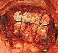
- Identify Landmarks: Our primary goal here is to expose the posterior arch of C1, the spinous process and laminae of C2, and potentially the inferior aspect of the occiput if an occipitocervical extension is planned.
Surgical Warning: Be extremely careful during lateral dissection at C1. The vertebral arteries make their medial turn in the groove on the superior surface of the C1 posterior arch. Excessive lateral dissection, especially with a wide Cobb elevator, can easily injure these vessels. Stay tight to the bone.
2. Exposure of C1 and C2 Posterior Elements
Surgeon: "Fellows, let's achieve a wide but safe exposure. Identify the posterior arch of C1. It's often palpable as a smooth, broad arch. Inferiorly, you'll feel the robust, bifid spinous process of C2."
- C1 Exposure: Gently retract the muscles laterally. Identify the posterior arch of C1. For C1 lateral mass screw placement, we need to expose the posterior aspect of the C1 lateral mass. This requires careful, limited lateral dissection.
- C2 Exposure: Expose the spinous process and laminae of C2. For C2 pedicle/pars screw placement, the entry point will be at the junction of the lamina and the inferior articular process.
- Hemostasis: Maintain meticulous hemostasis throughout the exposure using bipolar cautery and bone wax as needed.
Surgical Warning: As you dissect laterally at C1, remember the C1 nerve root (suboccipital nerve) exits cranial to the posterior arch of C1. The C2 nerve root (greater occipital nerve) exits between C1 and C2. Excessive traction or direct injury can cause dysesthesia.
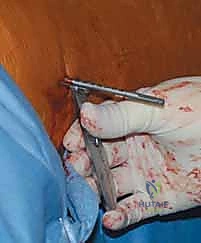
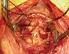
3. C1 Lateral Mass Screw Placement
Surgeon: "Now, let's address the C1 lateral mass screws. This is a critical step, requiring precision due to the proximity of the vertebral artery and C1 nerve root. We'll aim for a bicortical purchase."
- Entry Point: Identify the posterior aspect of the C1 lateral mass. The entry point is typically at the intersection of a line bisecting the C1 posterior arch and a line drawn through the center of the C1 lateral mass.
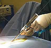
- Pilot Hole: Use a high-speed burr or an awl to create a pilot hole.
- Direction: The screw trajectory is crucial:
- Axial Plane: Aim approximately 10-15 degrees medially from the sagittal plane. This directs the screw away from the vertebral artery laterally and towards the anterior arch.
- Sagittal Plane: Aim slightly superior, approximately 10-15 degrees cephalad. This trajectory avoids the C1 nerve root superiorly and the C2 articulation inferiorly.
- Drilling: Use a small drill bit (e.g., 2.0mm) with a drill guide. Drill slowly and under constant irrigation.
- Depth: Advance the drill bicortically, typically 30-40mm, confirming depth with a calibrated depth gauge.
- Palpation/Probing: After drilling, use a ball-tipped probe to carefully palpate the walls of the pilot hole in all directions (superior, inferior, medial, lateral, anterior) to ensure no cortical breach.
- Tapping: Tap the hole with a tap one size smaller than the chosen screw diameter.
- Screw Insertion: Insert the C1 lateral mass screw (typically 3.5mm or 4.0mm diameter) carefully, ensuring good purchase. Do not overtighten.
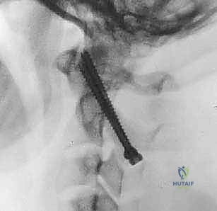
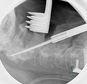
FIG 5 • The entry point for the C1 lateral mass screw is identified. A high-speed burr is used to create a pilot hole.
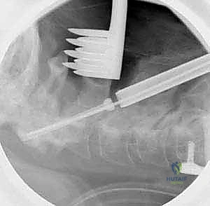
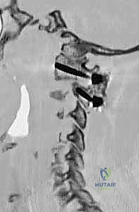
FIG 5 • The screw is directed 10 to 15 degrees medially and 10 to 15 degrees cephalad.
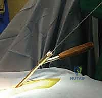
FIG 5 • The screw is advanced bicortically, with a typical length of 30 to 40 mm.
Surgical Warning: C1 Lateral Mass Screws:
* Vertebral Artery Injury: The most feared complication. Excessive lateral or inferior trajectory can injure the vertebral artery in its groove or as it exits the transverse foramen. Preoperative CTA/MRA is essential. If a ponticulus posticus is present, adjust trajectory or consider alternative fixation.
* C1 Nerve Root Injury: Excessive superior trajectory can injure the C1 nerve.
* Insufficient Purchase: Ensure bicortical purchase for maximal stability.
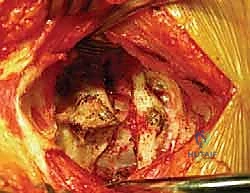
4. C2 Pedicle/Pars Screw Placement
Surgeon: "Next, we move to the C2 pedicle/pars screws. This technique offers excellent biomechanical stability and avoids the transarticular trajectory's challenges. The C2 pedicle is a strong bone corridor."
- Entry Point: The entry point for the C2 pedicle screw is typically at the junction of the lateral mass (inferior articular process) and the lamina, inferior to the C1-C2 facet joint. It's often at the superior aspect of the C2 pars interarticularis.
- Pilot Hole: Use an awl or high-speed burr to create a pilot hole.
- Direction: The trajectory is critical and often requires careful fluoroscopic guidance.
- Axial Plane: Aim approximately 20-30 degrees medially, towards the odontoid process. This directs the screw into the C2 body.
- Sagittal Plane: Aim approximately 20-40 degrees cephalad, parallel to the superior endplate of C2. This ensures the screw stays within the pedicle and body.
- Drilling: Use a small drill bit (e.g., 2.0mm) with a drill guide. Advance the drill slowly.
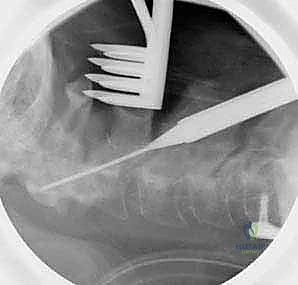
- Fluoroscopic Guidance: Obtain frequent lateral and AP fluoroscopic images to confirm trajectory and depth. On the lateral view, the screw should be parallel to the C2 superior endplate and directed towards the anterior cortex. On the AP view, it should be directed towards the midline.
- Depth: Advance the drill to the anterior cortex of the C2 body, typically 28-36mm.
- Palpation/Probing: After drilling, use a ball-tipped probe to carefully palpate the walls of the pilot hole to ensure no cortical breach. Feel for a solid bony tunnel.
- Tapping: Tap the hole with a tap one size smaller than the chosen screw diameter.
- Screw Insertion: Insert the C2 pedicle screw (typically 3.5mm or 4.0mm diameter) carefully.
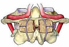
FIG 6 • A. The entry point for the C2 pedicle screw is at the junction of the lateral mass and the lamina.
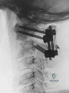
*FIG 6 • B. The screw is directed
Additional Intraoperative Imaging & Surgical Steps
REFERENCES
References
- Whereas Patients Undergoing The Brooks Or Gallie Procedure Obtain A Maximal Fusion Rate With Postoperative Halovest Immobilization, The Modern Screw Fixation Methods Yield Fusion Rates In Excess Of 90% With Only Cervical Collars Worn For 6-12 Weeks.
-
Boden SD, Dodge LD, Bohlman HH, et al. Rheumatoid arthritis of the cervical spine: a long-term analysis with predictors of paralysis and recovery. J Bone Joint Surg Am 1993;75A:1282–1297.
-
Brooks AL, Jenkins EW. Atlanto-axial arthrodesis by the wedge compression method. J Bone Joint Surg Am 1978;60A:279–284.
-
Cothren CC, Moore EE, Ray CE Jr, et al. Cervical spine fracture patterns mandating screening to rule out blunt cerebrovascular injury. Surgery 2007;141:76–82.
-
Currier BL, Todd LT, Maus TP, et al. Anatomic relationship of the internal carotid artery to the c1 vertebra: a case report of the cervical reconstruction for chordoma and pilot study to assess the risk of screw fixation of the atlas. Spine 2003;28:461–467.
-
Fielding JW, Hawkins RJ, Ratsan SA. Spine fusion for atlanto-axial instability. J Bone Joint Surg Am 1976;58A:400–407.
-
Gallie W. Fractures and dislocations of the cervical spine. Am J Surg 1939;46:495–499.
-
Goel A, Laheri V. Plate and screw fixation for atlanto-axial subluxation. Acta Neurochir (Wien)1994;129:47–53.
-
Gorek J, Acaroglu E, Berven S, et al. Constructs incorporating intralaminar C2 screws provide rigid stability for atlantoaxial fixation. Spine 2005;30:1513–1518.
-
Harms J, Melcher RP. Posterior C1-2 fusion with polyaxial screw and rod fixation. Spine 2001;26:2467–2471.
-
Jeanneret B, Magerl F. Primary posterior fusion of C1-2 in odontoid fractures: indications, techniques, and results of transarticular screw fixation. J Spinal Disord 1992;5:464–475.
-
Mandel I, Kambach B, Petersilge C, et al. Morphologic considerations of C2 isthmus dimensions for the placement of transarticular screws. Spine 2000;25:1542–1547.
-
McCulloch PT, France J, Jones DL, et al. Helical computed tomography alone compared with plain radiographs with adjunct computed tomography to evaluate the cervical spine after high-energy trauma. J Bone Joint Surg Am 2005;87:2388–2394.
-
McGuire RA, Harkey HL. Modification of technique and results of atlantoaxial transfacet stabilization. Orthopaedics 1995;18:1029–1032.
-
Panjabi M, Dvorak J, Duranceau J, et al. Three-dimensional movements of the upper cervical spine. Spine 1988;13:726–730.
-
Stubbs D. The arcuate foramen: variability in distribution related to race and sex. Spine 1992;17:1502–1504.
-
White A, Panjabi M. The clinical biomechanics of the occipitoatlantoaxial complex. Orthop Clin North Am 1978;9:867–878.
-
Young JP, Young PH, Ackermann MJ, et al. The ponticulus posticus: implications for screw insertion into the first cervical lateral mass. J Bone Joint Surg Am 2005;87A:2495–2498.
-
The type of collar used and duration of wear should be in accordance with surgeon judgment about host bone, security of fixation, anticipated patient compliance, etc.
OUTCOMES
- Jeanneret and Magerl 10 achieved solid fusion in 13 patients stabilized with the transarticular screw technique.
-
McGuire and Harkey 13 showed solid fusion in 8 patients using a transfect screw technique.
-
Fielding and associates 5 achieved fusion in 45 of 46 patients with fractures using the Gallie technique.
-
Brooks and Jenkins 2 used a C1–2 sublaminar wiring technique to achieve fusion in 14 out of 15 patients.
-
Harms 9 reported fusion in all 37 patients with C1 lateral mass and C2 pedicle minipolyaxial screw and rod construct.
-
Cost-effectiveness: The Goel C1–2 articular mass method has been popularized by Harms, and is offered as less risky than the Magerl method with respect to the vertebral artery. However, in the right patient, the Magerl method has proved to be quite safe. The cost of two 4.0-mm cannulated bone screws is substantially less than four polyaxial screws and a pair of rods.
COMPLICATIONS
- Vertebral artery and internal carotid artery injuries
-
Infection
-
Malpositioned screw
-
Nonunion
-
C2 neuralgia
-
C1–2 hyperextension with Brooks or Gallie procedure if the C1 and C2 arches are compressed together.
You Might Also Like