Biomechanics of Implant Design and Fracture Fixation: A Comprehensive Guide

Key Takeaway
Understanding the biomechanics of implant design and fracture fixation is essential for orthopaedic surgeons. This guide details the material properties of bone, loading modes, and the structural mechanics of pins, wires, and screws. By mastering AO principles, including lag screw techniques and interfragmentary compression, surgeons can optimize construct stability, mitigate implant fatigue, and promote reliable bone healing in complex fracture patterns.
Comprehensive Introduction and Patho-Epidemiology
The foundation of operative orthopaedics rests upon a profound understanding of the biomechanics of implant design and fracture fixation. Evaluating the failure of bone requires a meticulous analysis of the type, magnitude, and rate of load, alongside the intrinsic material and structural properties of the bone itself. The modern orthopaedic surgeon must transcend the role of a mere carpenter; they must operate as an applied biomechanical engineer, manipulating the mechanical environment of a fracture to dictate the biological response of bone healing. The interplay between the mechanical stability provided by an implant and the biological vitality of the surrounding soft tissue envelope defines the ultimate success or failure of any osteosynthesis construct.
Historically, the Arbeitsgemeinschaft für Osteosynthesefragen (AO) revolutionized fracture care by championing absolute stability and primary bone healing through rigid internal fixation. However, the patho-epidemiology of implant failure over the ensuing decades revealed that absolute rigidity, particularly in multifragmentary diaphyseal fractures, often led to catastrophic implant fatigue and nonunion due to profound devascularization of the fracture fragments. This catalyzed a paradigm shift toward "biological osteosynthesis," emphasizing relative stability, preservation of the periosteal blood supply, and the promotion of secondary bone healing via robust callus formation. Understanding this evolution is critical for interpreting the complex biomechanical demands placed on contemporary orthopaedic implants.
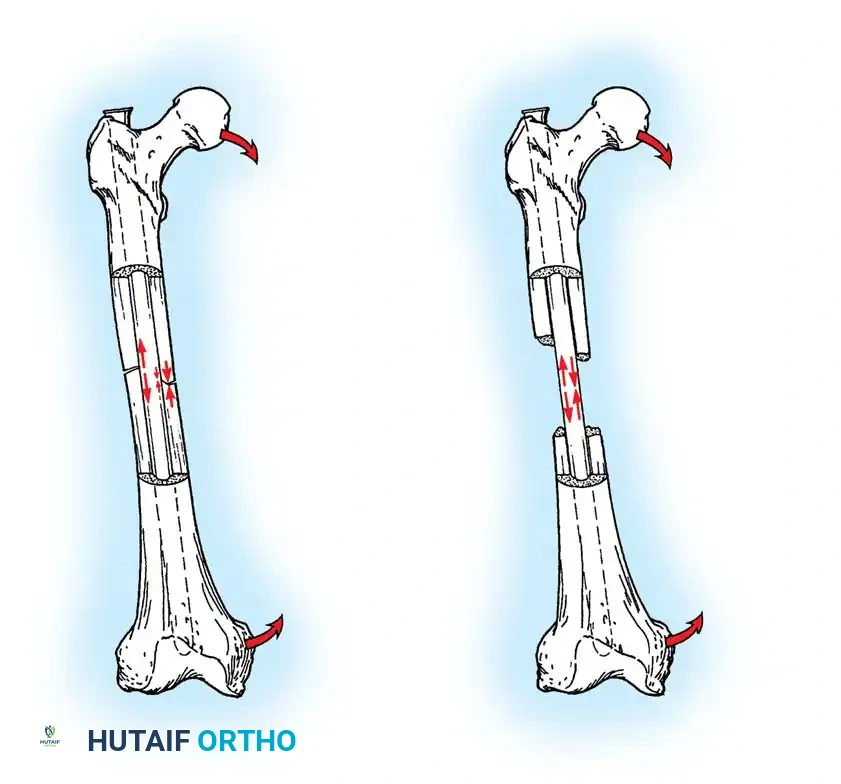
Fracture patterns are dictated by the mode of loading, which offers critical insight into the mechanism of injury, the energy dissipated, and the likelihood of associated soft-tissue injuries. Loads are classically described as tension, compression, bending, shear, torsion, or a complex combination of these forces. For instance, pure torsional loading typically generates a spiral fracture pattern, whereas high-energy bending forces produce transverse or short oblique fractures, frequently accompanied by a butterfly fragment on the compression side. The specific mode of bone failure can accurately predict the extent of the soft-tissue hinge and the inherent stability of the resulting fracture, thereby guiding the surgeon's choice of implant and fixation strategy.
Furthermore, the epidemiology of fracture fixation failure is intrinsically linked to the race between implant fatigue and bone union. Devices utilized to stabilize the human skeleton are subjected to relentless, cyclical loading and deforming forces. While these forces rarely cause acute load-to-failure (as occurs during the initial traumatic event), orthopaedic implants are highly susceptible to fatigue failure if the bone does not regenerate rapidly enough to share, and eventually accommodate, the physiological load. Consequently, the preoperative plan must rigorously account for patient-specific factors—such as bone mineral density, body mass index, and compliance with weight-bearing restrictions—to mitigate the risk of premature construct failure.
Detailed Surgical Anatomy and Biomechanics
Intrinsic Biomechanics of Bone
Bone is a highly complex, viscoelastic, and anisotropic material, meaning it exhibits different stress-strain relationships depending on the direction and rate at which stress is applied. Because of its viscoelastic nature, bone becomes stiffer and sustains higher loads before failure when subjected to high loading rates. This explains why high-velocity trauma results in explosive, highly comminuted fracture patterns with massive energy transfer to the surrounding soft tissues, whereas low-velocity falls typically result in simple fracture patterns. The anisotropic properties of bone dictate that it is strongest in compression, weaker in tension, and weakest in shear.
Furthermore, cancellous and cortical bone differ significantly due to the porosity and diameter of their respective cross-sections. In vitro studies demonstrate that cortical bone, being dense and highly mineralized, fractures when strain exceeds a mere 2% of its original length. In stark contrast, the highly porous, trabecular structure of cancellous bone does not fail until strain exceeds 7%, allowing it to absorb significant energy before catastrophic failure. This fundamental difference dictates that implants anchoring in cortical bone rely on fine-pitch threads for maximal surface area engagement, whereas implants in cancellous bone require deep, wide-pitch threads to capture a sufficient volume of trabecular bone to resist pull-out forces.
Material Properties of Orthopaedic Implants
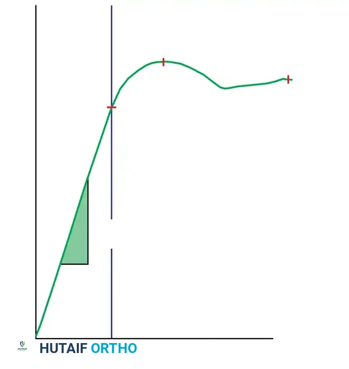
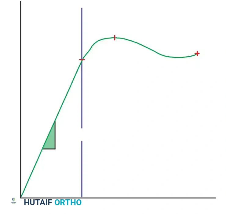
The material properties of orthopaedic implants are graphically expressed by stress-strain curves, which delineate the elastic and plastic deformation zones. The slope of the elastic zone represents the modulus of elasticity (Young's modulus), a measure of the material's intrinsic stiffness. Stainless steel (316L) possesses a high modulus of elasticity, making it exceptionally rigid and ideal for achieving absolute stability in articular fractures. However, its high stiffness can lead to stress shielding in diaphyseal bone. Titanium alloys (e.g., Ti-6Al-4V) have a modulus of elasticity closer to that of cortical bone, reducing stress shielding and offering superior biocompatibility and fatigue resistance, making them the material of choice for intramedullary nails and modern locking plates.
Clinical Pearl: Most orthopaedic implants are designed to function strictly within the elastic deformation phase of the load-deformation curve. Theoretically, there exists an optimal elastic range of micro-motion that favors secondary bone healing (callus formation), but this range differs drastically between direct (primary) and indirect (secondary) forms of bone healing. Perren's strain theory postulates that granulation tissue can tolerate 100% strain, cartilage 10%, and lamellar bone only 2%. Therefore, the implant must dictate a mechanical environment that keeps interfragmentary strain below the tolerance of the desired healing tissue.
Structural Properties and Implant Geometry
While material properties are intrinsic to the metal, structural properties are delineated by load-deformation curves and are dictated by the implant's geometry. The structural stiffness of an implant in bending is proportional to its area moment of inertia ($I$), whereas its stiffness in torsion is proportional to its polar moment of inertia ($J$). For a solid cylindrical implant like a Steinmann pin, the area moment of inertia is proportional to the radius to the fourth power ($I = \frac{\pi r^4}{4}$). This exponential relationship means that a seemingly minor increase in the diameter of a pin or intramedullary nail results in a massive increase in its bending stiffness and fatigue life.
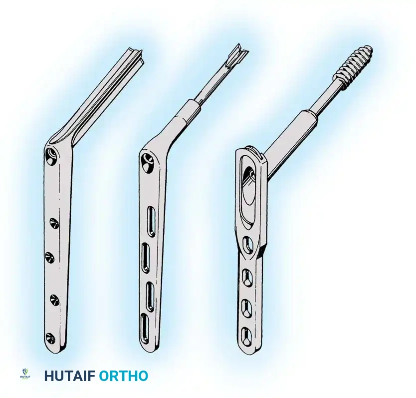
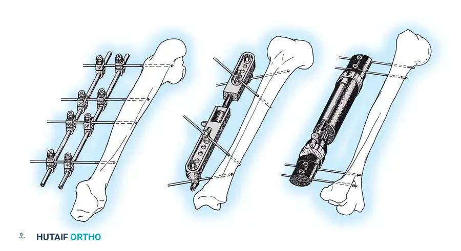
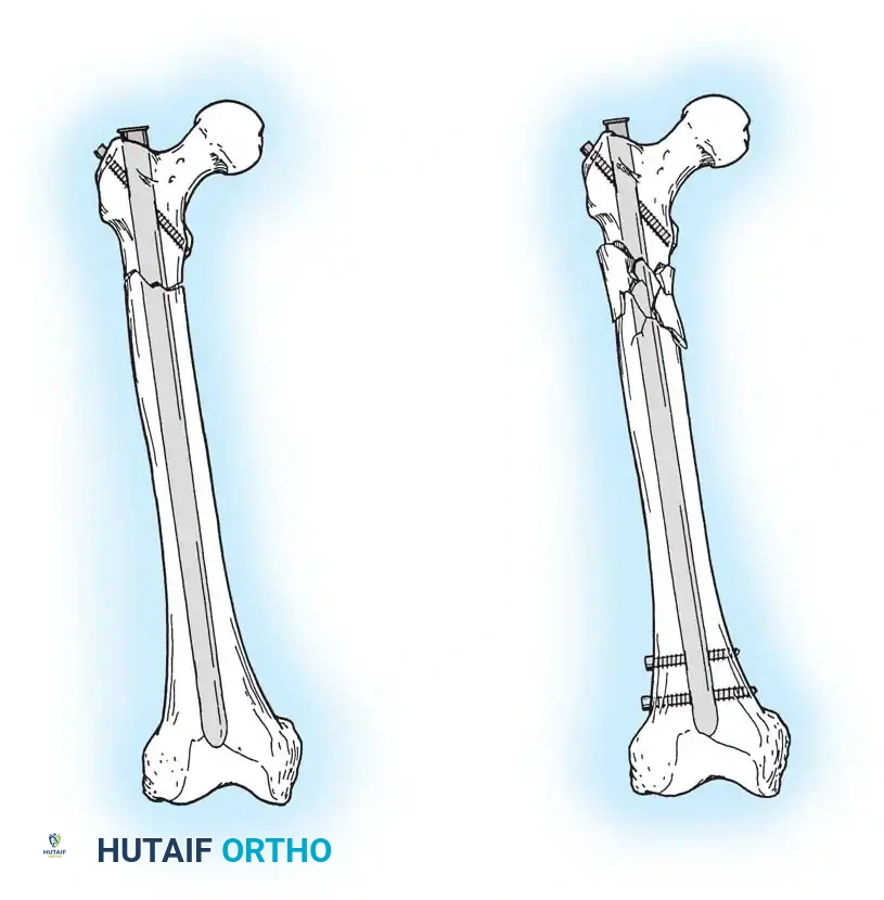
Küntscher originally described the fundamental biomechanical differences between pins, rods, and nails used for fracture fixation based on their structural interaction with the medullary canal:
* Pins: Resist alignment changes only.
* Rods: Resist deviations in alignment and translation.
* Nails: Resist changes in alignment, translation, and rotation (typically achieved via an interference fit or interlocking screws).
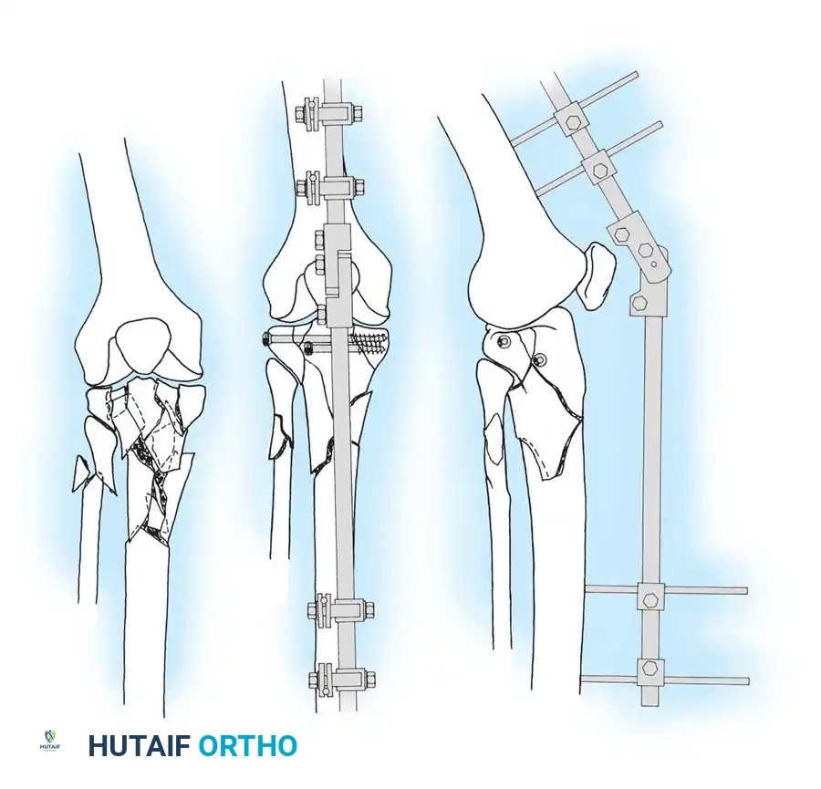
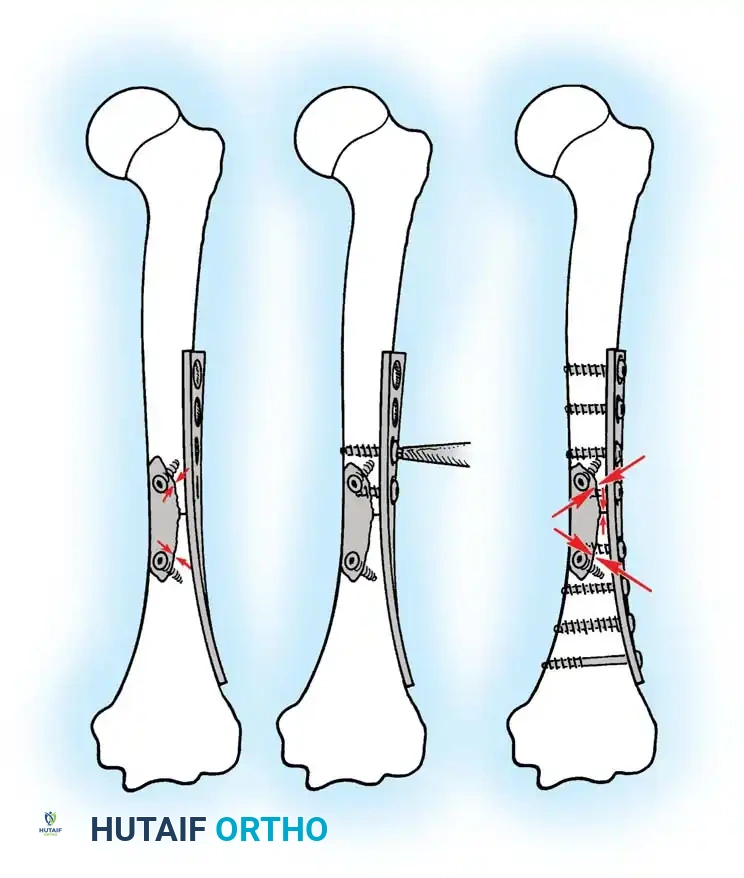
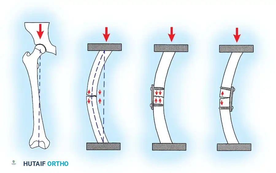
When selecting an intramedullary nail, plate and screws, or external fixator, the surgeon must meticulously evaluate these structural properties. A plate applied to the tension surface of a fractured bone acts as a tension band, converting tensile forces into compressive forces at the opposite cortex. Conversely, a plate applied to the compression surface will be subjected to massive bending moments, rapidly leading to fatigue failure if the opposite cortex is comminuted and unable to share the load.
Exhaustive Indications and Contraindications
The selection of a fracture fixation construct is a highly nuanced decision that must balance the mechanical demands of the fracture with the biological capacity of the host. Absolute stability, achieved via interfragmentary compression (lag screws) and neutralization plating, is strictly indicated for articular fractures where anatomical reduction is paramount to prevent post-traumatic osteoarthritis. In contrast, relative stability, achieved via intramedullary nailing, bridge plating, or external fixation, is indicated for highly comminuted diaphyseal fractures where preserving the soft tissue envelope and stimulating callus formation is prioritized over anatomical reduction of every intermediate fragment.
The use of specific implants also depends on the quality of the host bone. Conventional plating relies on friction between the plate and the bone surface, generated by the axial tension of the screws. In severely osteoporotic bone, the screws may strip before adequate friction is achieved. In such scenarios, locked plating is indicated. Locking screws feature a threaded conical head that locks directly into a corresponding threaded hole in the plate, creating a fixed-angle construct that does not rely on plate-to-bone friction. This transfers the stress from the bone-screw interface to the stronger screw-plate interface.
Contraindications are equally critical to recognize. For instance, rigid anatomical plating of a highly comminuted diaphyseal fracture is contraindicated, as the extensive periosteal stripping required will inevitably lead to devascularization, delayed union, and eventual implant fatigue. Similarly, the use of unreamed intramedullary nails in the presence of an active intramedullary infection is absolutely contraindicated due to the risk of propagating the infection throughout the entire diaphysis.
| Fixation Modality | Primary Indications | Relative Contraindications | Absolute Contraindications |
|---|---|---|---|
| Lag Screw & Neutralization Plate | Simple articular or periarticular fractures; transverse/oblique diaphyseal fractures requiring absolute stability. | Severe osteoporosis (high risk of screw pull-out); highly comminuted fractures. | Active infection at the surgical site; critical soft tissue compromise preventing coverage. |
| Intramedullary Nailing (Reamed) | Diaphyseal fractures of the femur and tibia; impending pathologic fractures. | Open fractures with severe contamination (Gustilo IIIB/IIIC); narrow medullary canal. | Active intramedullary osteomyelitis; uncorrected coagulopathy. |
| Locked Bridge Plating | Comminuted metaphyseal/diaphyseal fractures; osteoporotic bone; periprosthetic fractures. | Simple transverse fractures where absolute stability is required (can lead to nonunion due to excessive stiffness). | Severe soft tissue defects precluding plate coverage; active infection. |
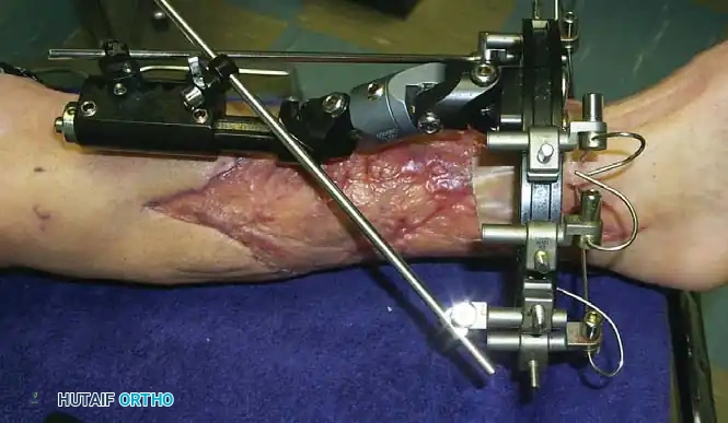
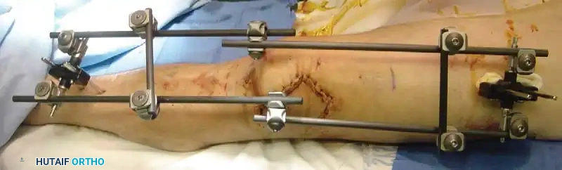
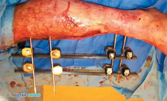
| External Fixation | Damage control orthopaedics (polytrauma); open fractures with massive soft tissue loss; severe burns over the fracture site. | Patient non-compliance (pin care); fractures where definitive internal fixation can be safely achieved. | Inadequate bone stock for pin purchase; definitive treatment of simple intra-articular fractures (unless spanning). |
Pre-Operative Planning, Templating, and Patient Positioning
Advanced Imaging and Digital Templating
Meticulous preoperative planning is the hallmark of the master orthopaedic surgeon. The process begins with obtaining high-quality, orthogonal radiographs of the injured extremity, ensuring that the joints above and below the fracture are visualized to rule out concomitant injuries. For complex intra-articular fractures, such as tibial plateau or pilon fractures, a fine-cut computed tomography (CT) scan with 3D reconstructions is mandatory to delineate the fracture geometry, assess articular depression, and plan the trajectory of subchondral raft screws.
Digital templating has largely replaced traditional acetate overlays, allowing the surgeon to accurately predict implant size, screw lengths, and the required reduction maneuvers. During templating, the surgeon must identify the "home run" screw trajectories—those that will provide maximal interfragmentary compression or the most robust purchase in dense trabecular bone. Furthermore, the surgeon must plan the sequence of reduction, often employing the "working from inside out" principle: reconstructing the articular block first, converting a complex fracture into a simpler metaphyseal-diaphyseal dissociation, and finally bridging the reconstructed articular block to the diaphysis.
Assessing the Soft Tissue Envelope
The timing of surgical intervention is dictated almost entirely by the condition of the soft tissue envelope. The Tscherne classification for closed fractures and the Gustilo-Anderson classification for open fractures must be rigorously applied. Operating through heavily contused, blistered, or edematous soft tissue exponentially increases the risk of wound dehiscence and deep infection. In cases of severe soft tissue compromise, a staged protocol is employed: immediate application of a spanning external fixator for skeletal stabilization, followed by delayed definitive internal fixation once the soft tissues have declared themselves and the "wrinkle sign" has appeared.
Patient Positioning and Intraoperative Fluoroscopy
Patient positioning must facilitate not only the surgical approach but also unimpeded access for the image intensifier (C-arm). For lower extremity diaphyseal fractures, a radiolucent fracture table or a flat Jackson table with a radiolucent extension is utilized. The surgeon must verify that perfect anteroposterior (AP) and lateral fluoroscopic views can be obtained without obstruction from the table pedestal or the contralateral limb.
For intramedullary nailing, positioning the patient supine with the affected limb adducted and the torso flexed laterally (the "scissored" position) allows for unobstructed access to the greater trochanter or piriformis fossa starting points. Careful padding of all bony prominences is imperative to prevent iatrogenic neurapraxia, particularly of the peroneal and ulnar nerves, during prolonged procedures.
Step-by-Step Surgical Approach and Fixation Technique
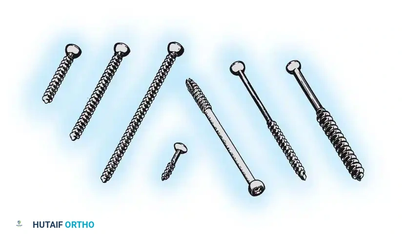
Principles of Screw Fixation and Lag Screw Technique
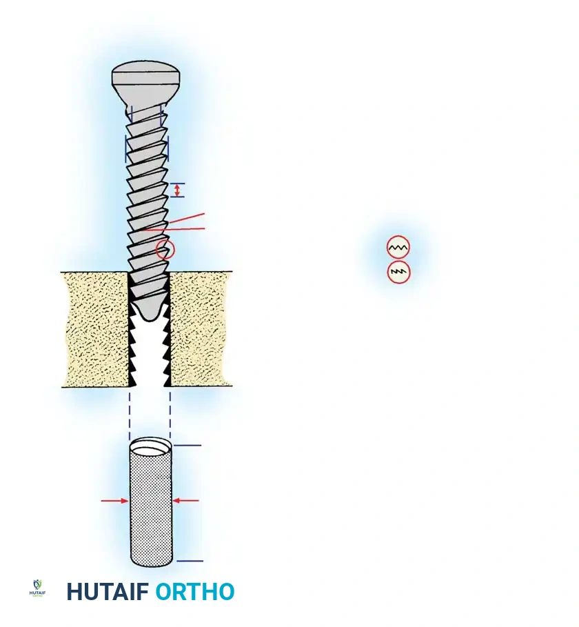
Screws are complex mechanical tools designed to convert torsional forces into compression. They feature a four-part construction: head, shaft, thread, and tip. The head serves as the attachment point for the screwdriver and acts as the counterforce against which compression generated by the screw acts on the cortical bone or plate. The thread is defined by its root (core) diameter, thread (outside) diameter, pitch (distance between adjacent threads), and lead. The root area determines the resistance of the screw to pull-out forces. If pull-out is a clinical concern due to osteoporotic or soft cancellous bone, a screw with a larger thread diameter and wider pitch is preferred. Conversely, if the bone is strong and implant fatigue is the primary concern, a screw with a wider root diameter provides a higher area moment of inertia, thus resisting bending and fatigue failure.
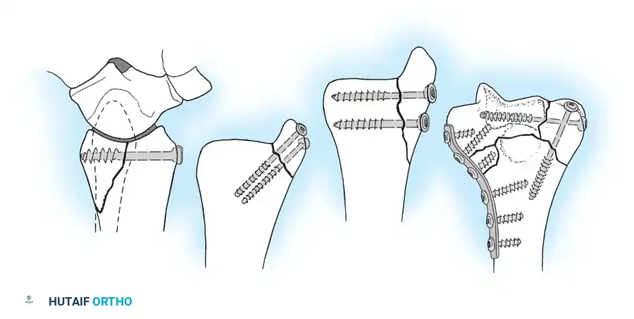
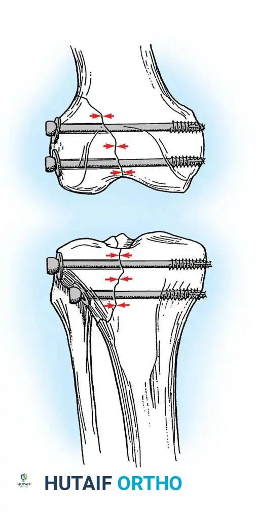
The use of a screw to convert torque forces into static interfragmentary compression across a fracture plane is one of the most valuable techniques in operative orthopaedics. Its success requires the screw to glide freely through the near bone fragment (gliding hole) and purchase securely only in the opposite cortex (thread hole). As the screw is tightened, the head exerts a load against the near cortex, forcefully compressing the fracture fragments together. Careful selection of the screw angle relative to the fracture plane is paramount. The lag screw must be directed perpendicular to the fracture plane to achieve maximal compression. If inserted at an incorrect angle, tightening the screw will induce shear forces, causing the fracture fragments to slide and displace.
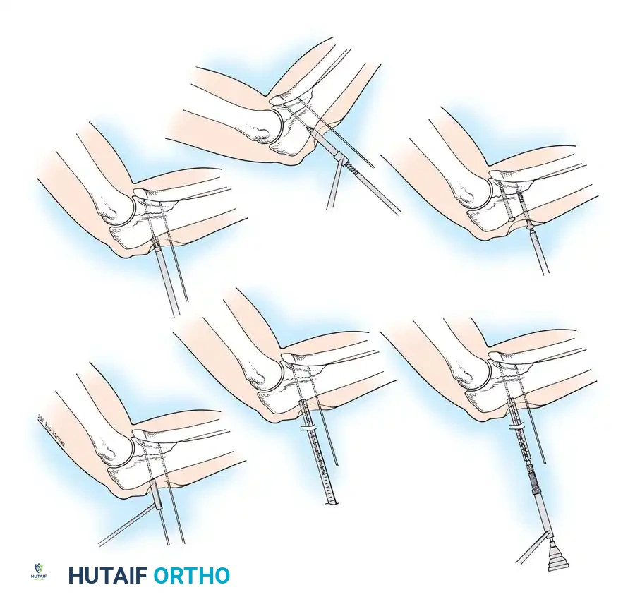
🔪 Surgical Technique: Interfragmentary Lag Screw Insertion
For transverse or short oblique fractures, lag screws must be protected by a neutralization plate. To achieve true interfragmentary compression, follow this standardized AO technique rigorously:
- Reduction: Anatomically reduce the fracture and secure the reduction with pointed reduction forceps or provisional Kirschner wires. Ensure the reduction forceps are placed orthogonal to the fracture plane to prevent shear during tightening.
- Plan the Trajectory: Plan the position of the screw so that it is inserted in the middle of the fragment, strictly perpendicular to the fracture plane.
- Drill the Gliding Hole: Use a drill bit matching the thread diameter of the screw (e.g., 3.5 mm drill for a 3.5 mm screw) to drill through the near cortex only. This ensures the threads will not purchase in the near fragment.
- Insert the Drill Sleeve: Place a specialized drill sleeve into the gliding hole. This centers the subsequent drill bit and protects the near cortex from eccentric reaming.
- Drill the Thread Hole: Use a drill bit matching the core diameter of the screw (e.g., 2.5 mm drill for a 3.5 mm screw) to drill through the far cortex.
- Countersink: Use a countersink tool on the near cortex to create a congruent bed for the screw head. This increases the contact area, distributing compressive forces and preventing stress risers or cortical splitting.
- Measure: Use a depth gauge to measure the required screw length. Ensure the hook catches the far cortex. Add 1-2 mm to ensure full thread engagement beyond the far cortex.
- Tap (If applicable): If using non-self-tapping screws, use a tap matching the thread profile to cut threads into the far cortex.
- Insert the Screw: Insert the screw and tighten carefully. As the head engages the countersunk near cortex, interfragmentary compression is achieved.
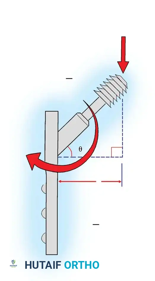
Plate Osteosynthesis Biomechanics
Plates are utilized to bridge fractures, neutralize forces on lag screws, or compress transverse fractures. The biomechanical function of a plate depends entirely on its application.
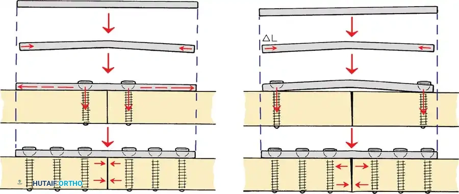
* Compression Plating: Utilized for transverse or short oblique fractures. By utilizing eccentric drill holes (as in a Dynamic Compression Plate - DCP), the spherical screw head slides down the angled geometry of the plate hole, translating the bone fragment axially and compressing the fracture site.
* Neutralization Plating: Applied to protect a lag screw from torsional, bending, and shear forces. The lag screw provides the interfragmentary compression, while the plate acts as a load-sharing device to prevent the screw from fatiguing.
* Bridge Plating: Utilized for highly comminuted diaphyseal fractures. The plate bypasses the zone of comminution, fixing only the proximal and distal main fragments. This provides relative stability, preserving the fracture hematoma and promoting secondary bone healing via callus formation.
Locking plates have revolutionized the management of osteoporotic and complex periarticular fractures. Because the screw head locks into the plate, the construct acts as an internal external fixator. The pull-out strength of a locked construct is equal to the sum of all the screws, making it highly resistant to failure in poor-quality bone. However, surgeons must be cautious not to make the construct too stiff, particularly in bridge plating scenarios, as this can suppress callus formation and lead to nonunion.
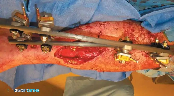
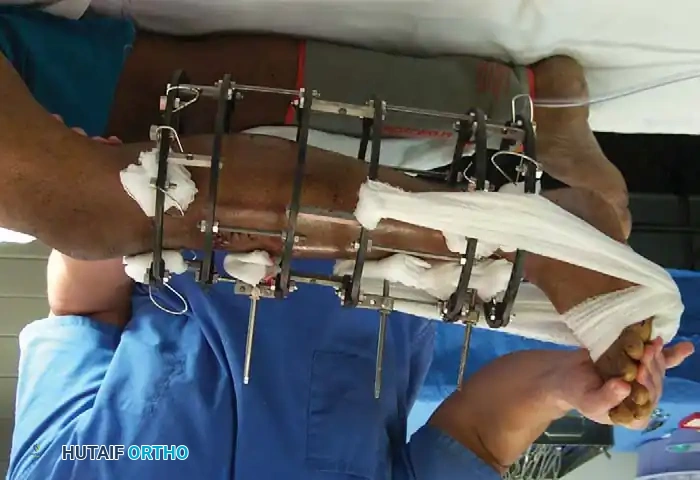
Pin and Wire Fixation Techniques
Kirschner wires (K-wires) and Steinmann pins are ubiquitous in orthopaedic surgery, frequently used for both provisional and definitive fracture fixation. Because their resistance to bending loads is inherently poor (due to a small area moment of inertia), if used as definitive fixation, they must be supplemented by external bracing, casting, or external fixation frames. Pin or wire fixation is usually adequate for small fragments in metaphyseal and epiphyseal regions, especially in fractures of the distal radius, foot, and hand.
Surgical Warning: Thermal necrosis of bone is a primary cause of pin loosening and subsequent infection. To prevent thermal damage to bone and surrounding soft tissues, pins must be inserted slowly using power equipment with frequent stops, or ideally, using a dedicated wire driver. Irrigation with cold saline during drilling is mandatory to dissipate heat.
Smooth wires are generally preferred to facilitate easier removal in the outpatient clinic after fracture healing. Threaded wires provide superior resistance to pull-out forces and hold fractures in place better for temporary fixation; however, the fracture fragments must be manually compressed during wire insertion to avoid distraction. Furthermore, threaded wires carry a higher risk of breakage at the thread-shank junction if the cortical bone is exceptionally hard.
Pitfall: Notching or bending the wire sharply at the bone interface should be avoided, as it creates a stress riser that drastically shortens the fatigue life of the implant.
Complications, Incidence Rates, and Salvage Management
Despite meticulous technique and profound biomechanical understanding, complications in fracture fixation remain a persistent challenge. The failure of an osteosynthesis construct is rarely a singular event; it is typically the culmination of mechanical overload, biological failure (nonunion), or catastrophic infection. Understanding the etiology of these complications is essential for rapid diagnosis and effective salvage management.
Implant fatigue failure is perhaps the most biomechanically predictable complication. If a fracture fails to unite, the implant is subjected to millions of cycles of physiological loading. No orthopaedic implant, regardless of its area moment of inertia or material composition, can withstand infinite cyclical loading without the load-sharing support of healed bone. Fatigue fractures of plates typically occur through an empty screw hole over the fracture gap, as this represents the area of lowest structural integrity and highest stress concentration.
Thermal necrosis during drilling or pin insertion is an iatrogenic complication that leads to a cascade of failures. When bone is subjected to temperatures exceeding 47°C for more than one minute, osteocyte death occurs. This necrotic ring of bone is rapidly resorbed by osteoclasts, leading to immediate loss of screw or pin purchase. In the context of external fixation, this manifests as pin tract loosening, which inevitably progresses to pin tract infection and loss of construct stability.
Infection remains the most devastating complication in operative orthopaedics. The presence of a foreign body (the implant) significantly lowers the inoculum required to establish an infection. Bacteria, particularly Staphylococcus aureus, rapidly adhere to the implant surface and form a protective glycocalyx biofilm. Once a biofilm is established, systemic antibiotics are largely ineffective, and the infection can only be eradicated through radical surgical debridement, implant removal, and dead space management.
| Complication | Estimated Incidence | Primary Etiology / Risk Factors | Salvage Management Strategy |
|---|---|---|---|
| Implant Fatigue Failure (Breakage) | 2-5% (higher in comminuted diaphyseal fractures) | Delayed union or nonunion; inadequate construct stiffness; premature weight-bearing. | Revision open reduction internal fixation (ORIF) with a stiffer construct; bone grafting (autograft) to stimulate biology. |
| Screw Pull-out / Loss of Fixation | 3-8% (significantly higher in osteoporotic bone) | Poor bone quality; thermal necrosis during drilling; over-tightening leading to stripped threads. | Revision with locked plating; use of larger diameter rescue screws; cement augmentation of screw tracts. |
| Pin Tract Infection (External Fixation) |
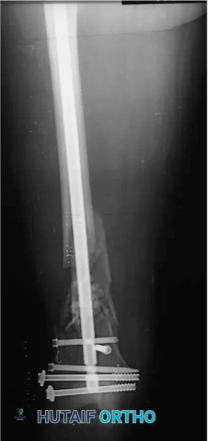
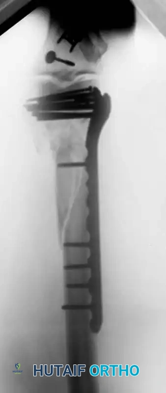
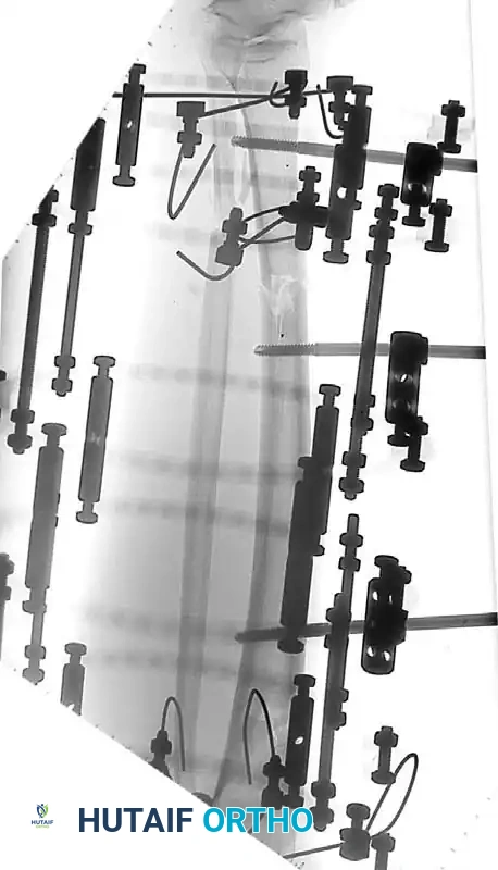
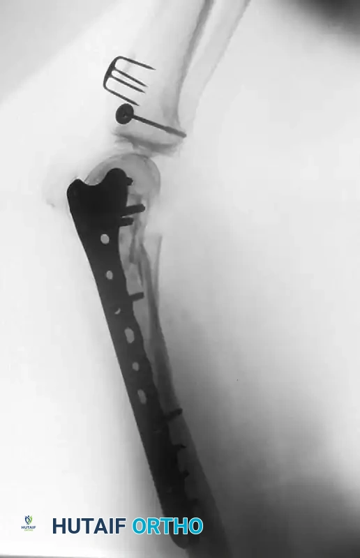
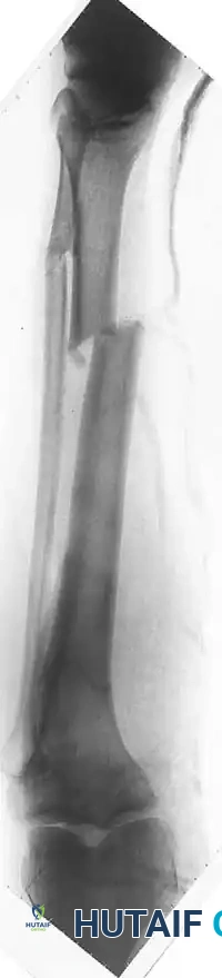
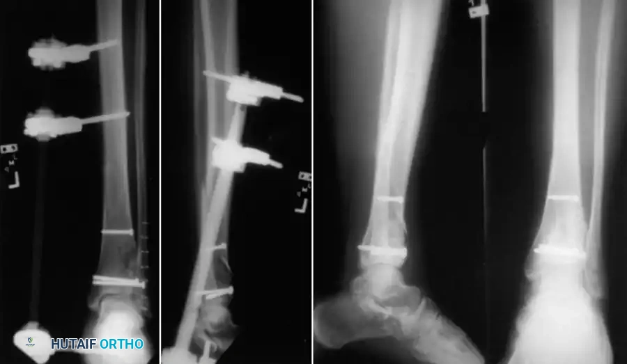
Clinical & Radiographic Imaging Archive