Masterclass in Lag Screw Fixation: Principles, Biomechanics, and Surgical Technique
Key Takeaway
Lag screw fixation is a fundamental orthopedic technique designed to achieve absolute stability through interfragmentary compression. By meticulously preparing a gliding hole in the near cortex and a threaded hole in the far cortex, surgeons can generate significant compressive forces across the fracture plane. This technique is paramount for intra-articular fractures, ensuring anatomical reduction, facilitating early mobilization, and minimizing the risk of post-traumatic osteoarthritis.
Comprehensive Introduction and Patho-Epidemiology
Screw fixation remains one of the most fundamental, ubiquitous, and biomechanically elegant techniques in operative orthopedics and traumatology. When applied with meticulous precision, it provides absolute stability by generating interfragmentary compression, which is the non-negotiable prerequisite for primary bone healing without intermediate callus formation. It is imperative for the orthopedic surgeon to understand that the "lag screw" is not a specific anatomical or manufactured type of screw, but rather a fundamental biomechanical principle and a highly specific surgical technique. The primary objective of lag screw fixation is to dynamically and rigidly compress two bone fragments together, obliterating the fracture gap and restoring anatomical continuity.
The biological imperative behind the lag screw principle is the facilitation of primary (direct) bone healing. In the presence of absolute stability and interfragmentary compression, the micro-strain at the fracture site is reduced to practically zero. This mechanical environment allows for direct Haversian remodeling. Osteoclastic cutting cones traverse the compressed fracture plane, immediately followed by osteoblasts that lay down new lamellar bone. This process bypasses the enchondral ossification phase entirely, meaning no cartilaginous intermediate or visible radiographic callus is formed. If the lag technique is executed poorly, resulting in a residual gap or micro-motion, the resultant high-strain environment will lead to either hypertrophic nonunion or catastrophic hardware failure as the screw is subjected to cyclical bending forces rather than static tension.
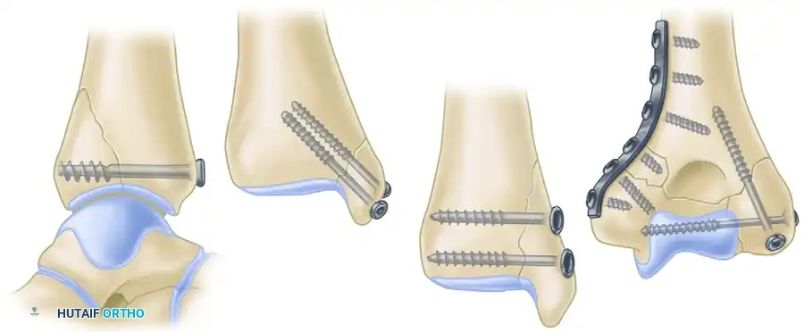
Epidemiologically, the application of the lag screw principle is ubiquitous across orthopedic trauma. It is the gold standard for the management of intra-articular fractures, where the restoration of articular congruity must be absolute to prevent post-traumatic osteoarthritis. Common applications include fractures of the medial and posterior malleoli, tibial plateau, distal humerus, and acetabulum. Furthermore, it is heavily utilized in simple oblique or spiral diaphyseal fractures (such as the tibia, radius, and ulna), where the fracture length is at least twice the diameter of the bone. In these diaphyseal applications, the lag screw is almost universally protected by a neutralization plate to shield the screw from functional bending and torsional loads, which a screw alone cannot withstand.
The evolution of this technique is deeply rooted in the foundational work of the Arbeitsgemeinschaft für Osteosynthesefragen (AO/ASIF) established in the late 1950s. The standardized protocols for creating a gliding hole and a threaded hole transformed fracture surgery from an era of prolonged cast immobilization and frequent malunions to an era of anatomical reduction, stable internal fixation, and early, pain-free mobilization. Mastery of this technique requires not only a profound understanding of bone biology but also an intimate familiarity with the physical properties of the implants and the surgical instruments utilized in their application.
Detailed Surgical Anatomy and Biomechanics
Understanding the intricate biomechanics of interfragmentary compression is critical for the orthopedic surgeon to prevent iatrogenic displacement during fixation. When a screw is inserted across a fracture plane using the lag technique, the rotational torque applied by the surgeon to the screw head is mechanically converted into axial tension along the core of the screw. According to Newton’s third law, this axial tension generates an equal and opposite compressive force across the fracture plane. For this compression to be effective, uniform, and non-destructive, the exact trajectory of the screw is of paramount importance.
The optimal trajectory for a lag screw is dictated by the geometry of the fracture. The screw must be directed at a precise right angle (90 degrees) to the fracture plane. If the screw is inserted at an angle other than perpendicular to the fracture, the compressive forces will not be evenly distributed across the cortical surfaces. Instead, asymmetrical loading occurs, introducing severe shearing forces. As the torque of the screw increases during final tightening, these shearing forces will cause the fragments to slide against one another, leading to a phenomenon known as "loss of reduction upon compression." This biomechanical mismatch not only destroys the anatomical reduction but also drastically reduces the total compressive force achieved, leaving the construct vulnerable to failure.
In diaphyseal fractures, the biomechanical ideal is slightly more complex. The screw should ideally bisect the angle formed by the perpendicular to the fracture plane and the perpendicular to the long axis of the bone. A screw placed perfectly perpendicular to the fracture plane provides maximum interfragmentary compression but offers minimal resistance to axial loading. Conversely, a screw placed perpendicular to the long axis of the bone resists axial loading well but provides suboptimal compression and risks shearing. Bisection of this angle provides a biomechanical compromise. However, in purely intra-articular fractures (e.g., a medial malleolus or a Hoffa fracture), perpendicularity to the fracture plane takes absolute precedence to maximize compression and perfectly maintain articular congruity.
The structural anatomy of the bone being fixated also dictates the biomechanical approach. Cortical bone is highly anisotropic, brittle, and dense, possessing high ultimate tensile strength but low tolerance for hoop stresses. When a standard cortical screw, which features a hemispherical undersurface at its head, is driven directly into the flat surface of cortical bone, it acts as a mechanical wedge. This wedging effect creates massive radial hoop stresses that can easily split the near cortex longitudinally. Therefore, countersinking is absolutely mandatory in cortical bone to create a matching hemispherical recess, which exponentially increases the surface area of contact, decreases the force per unit area, and safely dissipates the compressive load. In contrast, cancellous bone is spongy, isotropic, and deformable. The use of washers is often required when lagging in metaphyseal or epiphyseal cancellous bone to prevent the screw head from sinking through the thin cortical shell and burying into the trabecular bone, which would instantly negate all compressive forces.
Exhaustive Indications and Contraindications
The decision to employ lag screw fixation must be based on a rigorous assessment of the fracture pattern, bone quality, soft tissue envelope, and the overall physiological status of the patient. While the technique is powerful, its misapplication in inappropriate fracture patterns is a common source of iatrogenic failure.
Absolute indications for lag screw fixation include intra-articular fractures where anatomical reduction is required to prevent step-offs or gaps in the articular cartilage. Examples include the posterior and medial malleoli, radial head fractures, capitellum fractures, and unicondylar fractures of the femur or tibia. In the diaphysis, lag screws are indicated for simple spiral or long oblique fractures (AO/OTA type A2 or A3) where the length of the fracture line is greater than twice the diameter of the bone. This geometry allows for the placement of multiple lag screws perpendicular to the fracture plane, providing a massive surface area for compression and intrinsic stability against shortening.
Contraindications revolve around fracture patterns that cannot support compression or bone quality that cannot sustain screw purchase. Short oblique fractures (where the fracture length is less than twice the bone diameter) are a classic contraindication; attempting to place a lag screw here often results in the screw traversing the fracture at a highly acute angle, leading to inevitable shearing and loss of reduction. Transverse fractures cannot be lagged, as a screw placed across a transverse fracture would lie parallel to the medullary canal. Highly comminuted fractures (AO/OTA type C) are also contraindicated for isolated lag screw fixation, as the intermediate fragments will collapse under compression, leading to profound shortening and malalignment. In these scenarios, bridge plating techniques designed for secondary bone healing are indicated.
| Parameter | Indications | Contraindications | Clinical Rationale |
|---|---|---|---|
| Fracture Geometry | Long oblique, spiral, intra-articular split fractures. | Short oblique, transverse, highly comminuted fractures. | Long oblique fractures allow perpendicular screw placement and large surface area for compression. Comminuted fractures collapse under compression. |
| Bone Quality | Normal to mildly osteopenic bone. | Severe osteoporosis, heavily irradiated bone, active osteomyelitis. | Severe osteoporosis precludes adequate thread purchase in the far cortex, leading to stripping and loss of the lag effect. Infection requires debridement, not hardware implantation. |
| Anatomical Location | Epiphyseal/metaphyseal articular blocks, diaphyseal simple fractures. | Diaphyseal fractures with massive segmental bone loss. | Articular blocks require absolute stability. Diaphyseal fractures with bone loss require spanning constructs (nails or bridge plates) to maintain length. |
| Soft Tissue Envelope | Closed fractures or open fractures after adequate debridement and soft tissue coverage. | Active cellulitis, compromised flaps, severe blistering over the planned incision. | Placing hardware through compromised soft tissue drastically increases the risk of deep infection and hardware exposure. |
Pre-Operative Planning, Templating, and Patient Positioning
Meticulous preoperative planning is the hallmark of the master orthopedic surgeon. The success of lag screw fixation is determined long before the first incision is made. Planning begins with the acquisition of high-quality orthogonal radiographs. For any intra-articular fracture or complex periarticular trauma, a fine-cut Computed Tomography (CT) scan with 2D multiplanar reformats (coronal, sagittal, axial) and 3D surface rendering is considered the standard of care. The CT scan allows the surgeon to conceptualize the fracture in three dimensions, identify occult fracture lines, map out the zones of comminution, and locate the primary fracture planes that will dictate screw trajectory.
Digital templating software must be utilized to pre-select the optimal screw diameter, length, and trajectory. The surgeon must decide between cortical and cancellous screws based on the anatomical region. For example, a dense diaphyseal fracture of the radius will require 3.5-mm cortical screws, whereas a medial malleolus fracture will typically require 4.0-mm partially threaded cancellous screws. Templating also helps anticipate the need for specialized equipment, such as specific drill bits, taps, reduction forceps with specialized tines, and appropriately sized washers. The surgeon should draw the fracture lines, the planned reduction, and the exact position of the lag screws and any supplementary neutralization plates.
Patient positioning is strictly dictated by the anatomical location of the fracture and must facilitate both the surgical approach and unhindered intraoperative fluoroscopy. The operating table must be radiolucent.
* Ankle Fractures: The patient is positioned supine. A bump is placed under the ipsilateral hip to internally rotate the leg, bringing the ankle into a neutral position (counteracting the natural external rotation of the lower limb). This allows perfect mortise and lateral fluoroscopic views without having to excessively manipulate the injured limb.
* Distal Humerus and Olecranon: The patient may be positioned in the lateral decubitus or prone position. The arm is draped over a radiolucent post or resting on a radiolucent arm board. This positioning is critical as it allows for full, unhindered flexion and extension of the elbow during the procedure, which is necessary for both reduction maneuvers and dynamic fluoroscopic evaluation of articular congruity.
* Tibial Plateau Fractures: Supine positioning on a radiolucent flat table with a ramp or triangle under the knee. The ability to flex the knee intraoperatively relaxes the deforming pull of the gastrocnemius and allows access to the posterior articular surface if necessary.
Preparation of the surgical field must be expansive. The draping should allow for extension of the incision if the fracture pattern dictates a wider exposure. A sterile tourniquet is often applied to the proximal limb to provide a bloodless field, which is essential for visualizing the minute details of articular reductions.
Step-by-Step Surgical Approach and Fixation Technique
The execution of a lag screw requires uncompromising precision. The following technique describes the classic AO/ASIF method for inserting a standard 4.5-mm cortical screw using the lag technique. This specific technique requires the deliberate creation of a gliding hole in the near cortex and a threaded hole in the far cortex.
Anatomical Reduction and Provisional Fixation
Direct exposure of the fracture is performed with meticulous handling of the soft tissues to preserve the periosteal blood supply. The fracture hematoma and any interposed soft tissue or periosteum must be aggressively cleared using a curette and irrigation. The fracture is then anatomically reduced using pointed reduction forceps (Weber clamps).
Clinical Pearl: When applying reduction forceps, the surgeon must place the tines exactly perpendicular to the fracture plane. This mimics the eventual compressive force of the lag screw. If the clamp is applied obliquely, the fracture will shear and displace. Once reduced, the fracture is provisionally secured with Kirschner wires (K-wires). It is critical that these K-wires are placed outside the planned trajectory of the definitive lag screws to prevent drill collision.
Drilling the Gliding Hole (Near Cortex)
The fundamental principle of the cortical lag screw is that the threads must not purchase in the near cortex. Therefore, a gliding hole is created. The surgeon selects a drill bit that matches the outer thread diameter of the chosen screw. For a 4.5-mm cortical screw, a 4.5-mm drill bit is used. This hole is drilled through the near cortex only. The trajectory of this drill pass is the most critical step of the procedure; it must be perfectly perpendicular to the fracture plane to prevent subsequent shearing.
Drilling the Thread Hole (Far Cortex)
To ensure the screw threads cut into and purchase the far cortex, a smaller thread hole is required. The surgeon inserts a specialized drill reduction sleeve (e.g., 4.5-mm to 3.2-mm) directly into the gliding hole. This sleeve is mandatory because it ensures that the subsequent thread hole is perfectly concentric and coaxial with the gliding hole. A 3.2-mm drill bit, which matches the core diameter of the 4.5-mm screw, is passed through the sleeve and drilled strictly through the far cortex.
Countersinking the Near Cortex
As previously discussed, cortical bone is brittle and sensitive to hoop stresses. The surgeon must use a countersink tool over the 4.5-mm gliding hole. By rotating the countersink, a hemispherical recess is created in the near cortex. This recess perfectly matches the undersurface of the screw head, maximizing contact area, increasing load dispersion, and preventing the near cortex from splitting longitudinally as the screw is tightened.
Depth Measurement and Tapping
The required screw length is determined using a standard depth gauge. The hook of the gauge is passed through both cortices, hooked onto the far cortex, and the barrel is seated flush against the countersunk near cortex. The surgeon should add 2 mm to the measured length. This ensures that the cutting flutes of the screw (which do not provide compressive purchase) fully exit the far cortex, guaranteeing that only fully formed threads engage the bone. Next, unless a self-tapping screw is utilized, the far cortex must be tapped. A 4.5-mm tap is inserted through the gliding hole, cutting threads only in the 3.2-mm hole in the far cortex.
Screw Insertion and Final Compression
A screw of the calculated length is inserted. As the screw head seats into the countersunk near cortex, the surgeon must carefully observe the fracture line. Visual confirmation of interfragmentary compression—the obliteration of the fracture gap—will occur as the screw is subjected to final tightening.
Surgical Warning: Do not remove the provisional fixation (K-wires) or holding forceps until the screw is fully seated and definitively tightened. Premature removal of provisional fixation removes rotational stability, and the rotational torque applied during the final turns of the screw can cause catastrophic loss of reduction.
The Cancellous Lag Screw Alternative
While the above describes using a fully threaded cortical screw as a lag screw via the overdrilling technique, the lag effect is routinely achieved in epiphyseal and metaphyseal bone using partially threaded cancellous screws. In these implants, the smooth shaft acts inherently as the gliding portion. The surgical technique is simplified: a single drill bit matching the core diameter is used for both cortices. However, it is absolutely critical that all threads pass completely beyond the fracture line into the far fragment. If even a single thread remains in the near fragment, the screw will act as a position screw, holding the fracture gap open and preventing any interfragmentary compression.
Complications, Incidence Rates, and Salvage Management
Despite the mechanical elegance of lag screw fixation, complications can and do occur, largely stemming from technical errors during execution, poor patient selection, or failure to respect the biomechanical limits of the implant. Recognizing these complications intraoperatively is crucial for immediate salvage.
Loss of reduction during screw tightening is perhaps the most frustrating intraoperative complication. It is almost exclusively caused by a failure to drill the gliding hole perpendicular to the fracture plane. When the screw is tightened, the asymmetrical compressive forces cause the fragments to slide. Salvage requires complete removal of the screw, re-reduction of the fracture, and placement of a new screw in a different, correct trajectory. The original hole must often be bypassed or filled with a bone graft substitute to prevent stress risers.
Thermal necrosis of the bone is a hidden but devastating complication. Drilling dense cortical bone, particularly the diaphyseal cortex of the femur or tibia, generates extreme friction and heat. If the temperature exceeds 47°C for more than one minute, irreversible osteocyte death occurs. This leads to a ring of necrotic bone around the screw, resulting in premature screw loosening, loss of fixation, and subsequent nonunion. This is entirely preventable by using sharp drill bits, clearing the flutes frequently, and utilizing copious, continuous chilled saline irrigation during all drilling and tapping steps.
Stripping of the far cortex occurs when the torque applied to the screw exceeds the shear strength of the bone threads in the far cortex. This is particularly common in osteoporotic bone or when the surgeon exhibits a heavy hand during final tightening. Once the threads strip, the screw spins freely, and the lag effect is entirely and permanently lost.
| Complication | Estimated Incidence | Etiology / Risk Factors | Salvage / Management Strategy |
|---|---|---|---|
| Loss of Reduction | 2 - 5% | Non-perpendicular drill trajectory; failure to countersink; premature K-wire removal. | Remove screw, re-reduce, drill new trajectory. Use pointed reduction forceps to counteract shear. |
| Thermal Necrosis | 1 - 3% | Dull drill bits; excessive drill speed; lack of saline irrigation. | Preventative: Copious irrigation. Salvage: If loosening occurs post-op, requires revision fixation and bone grafting. |
| Far Cortex Stripping | 5 - 10% (Higher in osteoporosis) | Overtightening; osteoporotic bone; selecting a screw that is too short. | Use a longer screw to engage the opposite cortex (if applicable); use a larger diameter "rescue" screw; augment with a neutralization plate. |
| Hardware Prominence | 10 - 15% | Failure to countersink; inadequate soft tissue coverage (e.g., medial malleolus). | Ensure proper countersinking. Post-operative management may require elective hardware removal after clinical and radiographic union is achieved. |
| Fracture Propagation | 1 - 2% | Inserting a screw too close to the fracture edge; massive hoop stresses from lack of countersinking. | Remove screw. Must transition to a bridge plating technique or use circumferential cerclage wiring if appropriate. |
Phased Post-Operative Rehabilitation Protocols
The postoperative protocol following lag screw fixation is not monolithic; it depends heavily on the anatomical location of the fracture, the quality of the host bone, patient compliance, and critically, whether the lag screws were used in isolation or were biomechanically protected by a neutralization plate. The ultimate goal of rehabilitation is to restore full, pain-free range of motion and strength while strictly protecting the mechanical integrity of the healing bone.
Phase 1: Immediate Post-Operative (Weeks 0-2)
In the immediate postoperative phase, the primary objectives are wound healing, edema control, and pain management. For isolated lag screw constructs (such as a medial malleolus fracture fixated with two cancellous screws), the fixation provides absolute stability but offers extremely poor resistance to functional bending and torsional forces. Therefore, the limb must be rigidly protected in a well-padded short leg cast or a locked rigid orthosis. Weight-bearing is strictly prohibited (non-weight-bearing).
Conversely, if the lag screw is protected by a robust neutralization plate (e.g., a distal fibula fracture or a diaphyseal radius fracture), the construct is significantly stronger. While weight-bearing restrictions still apply, early active and active-assisted range of motion (ROM) of the adjacent joints is highly encouraged within days of surgery to prevent capsular contracture and joint stiffness.
Phase 2: Intermediate Healing and Mobilization (Weeks 2-6)
At the two-week mark, sutures are typically removed following a thorough wound inspection. Radiographs are obtained to confirm the maintenance of reduction and hardware position. It is critical for the surgeon to educate the patient and junior staff that because lag screw fixation promotes primary bone healing, there will be no visible bridging callus on the radiographs. Successful healing is indicated solely by the gradual fading and obliteration of the fracture line.
For isolated screw constructs, immobilization is generally continued, though a transition to a removable fracture boot may be permitted to allow for gentle, non-weight-bearing ROM exercises in a controlled setting. For plated constructs, physical therapy is escalated to include progressive resistance exercises, and touch-down weight-bearing may be initiated depending on radiographic progression.
Phase 3: Consolidation and Return to Function (Weeks 6-12+)
By six to eight weeks, clinical union (absence of pain on palpation or stress) and radiographic consolidation should be evident. Weight-bearing is progressively advanced from partial to full weight-bearing as tolerated. Physical therapy focuses on proprioception, gait mechanics, and the restoration of baseline muscular strength. High-impact activities and sports are generally restricted until the 12-to-16-week mark, contingent upon complete obliteration of the fracture line and the return of symmetrical limb strength. If hardware prominence becomes symptomatic (e.g., painful bursitis over the screw heads at the medial malleolus), elective hardware removal can be discussed, but this should never be performed prior to 6 to 12 months postoperatively to avoid the risk of re-fracture through the screw holes.
Summary of Landmark Literature and Clinical Guidelines
The principles of lag screw fixation are not merely empirical; they are deeply rooted in decades of rigorous biomechanical research and clinical validation. The foundational texts of the AO/ASIF, spearheaded by pioneers such as Martin Allgöwer, Maurice Müller, and Robert Schneider, established the standardized techniques for hole preparation and interfragmentary compression that remain the global standard of care today. Their early work demonstrated that anatomical reduction combined with rigid internal fixation drastically reduced the incidence of "fracture disease"—a syndrome characterized by chronic edema, joint stiffness, and profound osteopenia associated with prolonged cast immobilization.
Perhaps the most critical theoretical framework underpinning this technique is Stephan Perren’s Strain Theory, published in 1979. Perren elucidated that the type of bone healing (primary vs. secondary) is entirely dictated by the mechanical strain environment at the fracture gap. Strain is defined as the change in gap length divided by the original gap length ($\Delta L / L$). Granulation tissue can tolerate 100% strain, cartilage can tolerate 10%, but lamellar bone can only form in an environment with less than 2% strain. By utilizing the lag screw technique to compress the fracture fragments, the gap length ($L$) is reduced to practically zero, and the absolute stability prevents any change in gap length ($\Delta L$). This reduces the strain to below 2%, creating the exact, highly specific biomechanical environment required for osteoclasts and osteoblasts to perform direct Haversian remodeling.
Modern clinical guidelines, including those published by the Orthopaedic Trauma Association (OTA) and the American Academy of Orthopaedic Surgeons (AAOS), continue to mandate the use of lag screw principles for intra-articular fractures. Recent literature has also focused on the optimization of screw design, such as the development of headless compression screws (e.g., Herbert screws or Acutrak screws). These implants utilize a variable pitch thread design—where the leading threads have a wider pitch than the trailing threads—to generate interfragmentary compression entirely within the bone, allowing the screw to be buried beneath articular cartilage without the need for countersinking or a prominent screw head. Despite these technological advancements in implant design, the fundamental biological and biomechanical laws governing interfragmentary compression remain immutable. Mastery of the standard cortical and cancellous lag screw techniques remains the cornerstone of orthopedic surgical education and practice.
