Masterclass in Orthopaedic Screw Fixation: Biomechanics, Implant Design, and Surgical Techniques
Key Takeaway
Orthopaedic screw fixation is a foundational technique in operative osteosynthesis, designed to convert rotational torque into interfragmentary compression. Understanding the intricate biomechanics of screw anatomy—including root diameter, pitch, and thread design—is critical for maximizing pull-out strength and minimizing fatigue failure. This guide details the principles of cortical, cancellous, and locking screws, providing surgeons with evidence-based protocols for lag screw application and rigid fracture stabilization.
INTRODUCTION TO ORTHOPAEDIC SCREW FIXATION
In the realm of operative orthopaedics, screw fixation remains the most fundamental and ubiquitous technique for achieving rigid internal fixation. Originally popularized by the Arbeitsgemeinschaft für Osteosynthesefragen (AO/ASIF) group in Switzerland, the modern application of bone screws is dictated by strict biomechanical principles. Screws are highly complex mechanical devices designed to convert applied rotational torque into linear compression across a fracture site or to secure implants (such as plates or nails) to the skeletal system.
For the orthopaedic resident, fellow, and practicing consultant, a profound understanding of screw anatomy, thread biomechanics, and precise surgical technique is non-negotiable. Failure to respect the mechanical properties of the bone-implant interface inevitably leads to hardware failure, loss of reduction, and nonunion.
ANATOMY AND BIOMECHANICS OF THE BONE SCREW
A standard orthopaedic bone screw is a four-part construct consisting of the head, shaft (shank), thread, and tip. Each component is engineered to perform a specific biomechanical function during osteosynthesis.
The Screw Head
The head of the screw serves two primary functions:
1. Attachment Interface: It provides a recess for the screwdriver to engage and transmit rotational torque. Common designs include hexagonal (hex), cruciate, slotted, Phillips, and the increasingly popular star-shaped (Torx or Stardrive) recesses, which offer superior torque transmission with reduced risk of "cam-out" or stripping.
2. Counterforce Generation: The undersurface of the head acts as the mechanical counterforce against the near cortex. As the screw threads advance into the far bone fragment, the head arrests further forward translation of the screw, thereby generating compression across the fracture interface.
The Shaft (Shank)
The shaft is the smooth, unthreaded portion of the screw located between the head and the threaded segment. In partially threaded screws, the shaft is designed to glide freely through the near cortex, ensuring that all compressive forces are directed across the fracture line rather than being dissipated within the proximal bone fragment.
The Thread Anatomy
The thread is the functional core of the screw, responsible for bone purchase and load transfer. Its geometry is defined by several critical parameters:
- Root (Core) Diameter: The solid inner core of the screw. The root area directly determines the screw's resistance to bending and fatigue failure. A larger root diameter yields a stronger screw but requires a larger drill hole, removing more host bone.
- Thread (Outside) Diameter: The maximum width across the outermost edges of the threads. The difference between the thread diameter and the root diameter determines the depth of the thread.
- Pitch: The linear distance between adjacent threads. Cancellous screws have a larger pitch (threads are further apart) to capture more bone volume, whereas cortical screws have a smaller pitch.
- Lead: The linear distance the screw advances into the bone with one complete 360-degree revolution. In standard single-thread screws, the lead equals the pitch.
Clinical Pearl: Biomechanical Trade-offs
When operating on osteopenic or soft cancellous bone, pull-out strength is the primary concern; therefore, a screw with a larger thread diameter and deeper threads is preferred. Conversely, in dense cortical bone where the implant will be subjected to high cyclic loading, fatigue failure of the metal is the primary concern; thus, a screw with a wider root diameter is mechanically superior.
Thread Design and Cross-Section
The cross-sectional profile of the thread dictates how forces are transmitted to the surrounding bone.
* V-Thread: Symmetrical threads commonly used in standard machine screws.
* Buttress Thread: Asymmetrical threads (standard in ASIF screws) designed to present a flat surface against the direction of pull-out, thereby maximizing resistance to extraction forces and optimizing interfragmentary compression.
The Screw Tip
The tip dictates how the screw enters the bone:
* Round/Blunt Tips: Require the drill hole to be pre-tapped with a cutting instrument to create a thread path before insertion.
* Self-Tapping Tips: Feature a cutting flute (trocar or trephine tip) that cuts its own thread pattern into the bone as it advances, eliminating the need for a separate tapping step.
CLASSIFICATION OF ORTHOPAEDIC SCREWS
Screws are broadly categorized based on their design, intended host bone, and mechanism of action. While traditional "machine screws" (threaded their entire length with V-threads) exist, modern orthopaedics relies heavily on ASIF-designed screws.
ASIF Cortical Screws
Designed specifically for dense diaphyseal bone, ASIF cortical screws are fully threaded with a relatively small pitch and shallow threads. They are available in standard diameters: 4.5 mm, 3.5 mm, 2.7 mm, 2.0 mm, and 1.5 mm. Because they are fully threaded, they function primarily as positional screws unless the near cortex is intentionally overdrilled to create a gliding hole, allowing them to function as lag screws.
ASIF Cancellous Screws
Engineered for the softer, trabecular bone of the metaphysis and epiphysis, cancellous screws feature a larger thread diameter, a thinner root diameter, and a wider pitch. This design maximizes the volume of bone captured between the threads, significantly increasing pull-out strength in spongy bone.
They are primarily available in 6.5 mm and 4.0 mm diameters. Crucially, they come in varying thread lengths (commonly 16 mm and 32 mm), regardless of the total length of the screw. This partial threading allows them to function inherently as lag screws without the need to overdrill the near cortex, provided the threads do not cross the fracture line.
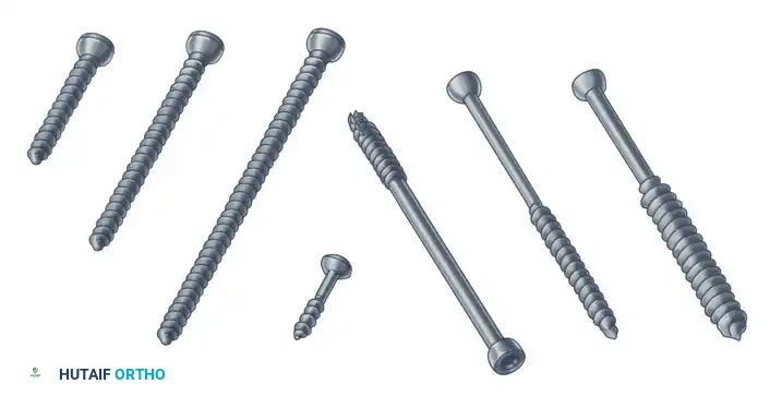
Malleolar Screws
A specialized subset of partially threaded screws, the malleolar screw (typically 4.5 mm) features a unique self-tapping trephine tip. It is historically utilized for the fixation of medial malleolar fractures, offering excellent compression without the need for extensive pre-tapping in the dense metaphyseal bone of the distal tibia.
Self-Tapping and Self-Drilling Screws
- Self-Tapping Screws: Possess a cutting flute at the tip to clear bone debris and cut threads. While they save surgical time, the fluted tip has slightly less pull-out strength if it remains within the bone; therefore, the fluted portion should ideally protrude just beyond the far cortex.
- Self-Drilling Screws: Feature a drill-bit tip, eliminating the need for both pre-drilling and tapping. These are most frequently utilized in external fixation pins (Schanz pins) and specific locking plate systems.
Locking Screws
Locking screws represent a paradigm shift in osteosynthesis. These are self-tapping screws equipped with machine threads on the screw head that mate perfectly with threaded holes in a locking plate. This creates a fixed-angle construct. Unlike conventional plating, which relies on friction between the plate and the bone, locking screws do not draw the plate to the bone. They require precise pre-drilling using specialized threaded drill guides to ensure the screw engages the plate exactly perpendicular to the hole.
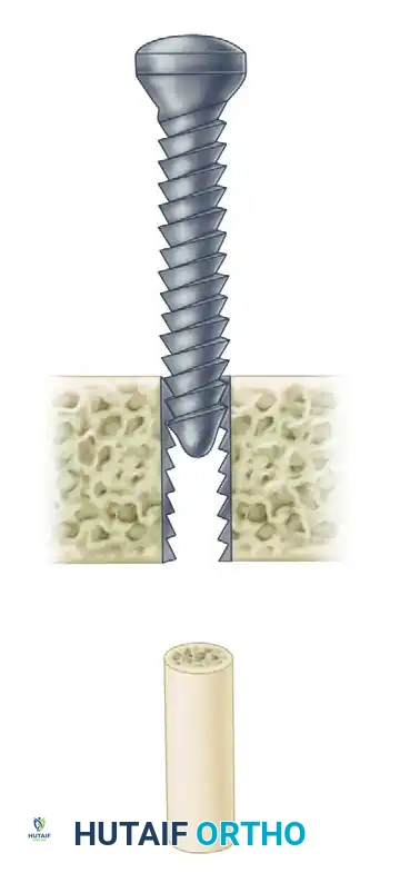
PRINCIPLES OF INTERFRAGMENTARY COMPRESSION (LAG SCREW TECHNIQUE)
The most critical application of a bone screw is the lag screw technique. This is not a specific type of screw, but rather a technique used to convert the torque of screw insertion into dynamic compression across a fracture plane. Absolute stability achieved through interfragmentary compression dictates primary bone healing without callus formation.
The Mechanics of Lagging
For a screw to compress two fragments together, it must glide freely through the near fragment (the cis cortex) and purchase only in the far fragment (the trans cortex). As the screw is tightened, the threads pull the far fragment toward the screw head, while the screw head pushes the near fragment toward the far fragment.
If a fully threaded screw is inserted across a fracture without overdrilling the near cortex, the threads will engage both fragments simultaneously. This holds the fragments in their exact current position (a positional screw) and makes interfragmentary compression mechanically impossible.
Trajectory and Inclination
The trajectory of the lag screw is paramount to maintaining anatomical reduction.
* The screw must be positioned at a right angle (90 degrees) to the fracture plane.
* If the screw is inserted at an incorrect angle (e.g., perpendicular to the long axis of the bone rather than the fracture plane), tightening the screw will introduce shear forces, causing the fracture fragments to slide and displace.
Surgical Warning: The Bisecting Angle Fallacy
Historically, some texts recommended a "bisecting angle" (halfway between the perpendicular to the bone axis and the perpendicular to the fracture plane). Biomechanically, this is only acceptable for fractures with less than 40 degrees of inclination. For highly oblique fractures (e.g., 60 degrees), utilizing a bisecting angle will inevitably result in shear displacement as the lag screw is tightened. Always aim perpendicular to the fracture plane.
STEP-BY-STEP SURGICAL TECHNIQUE: CORTICAL LAG SCREW INSERTION
The insertion of a fully threaded cortical screw using the lag technique requires a meticulous, multi-step process. The following protocol outlines the standard AO technique for a 4.5 mm cortical lag screw.
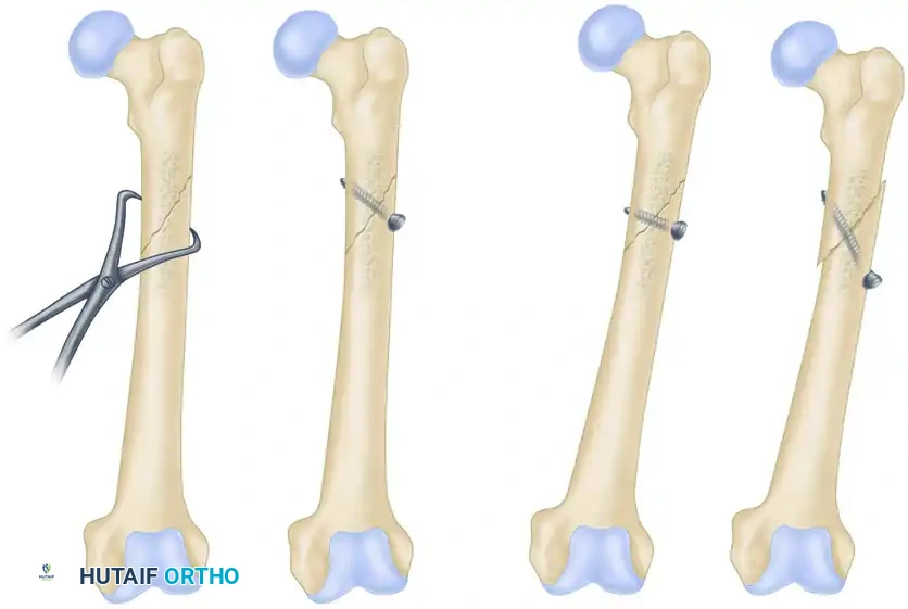
Step 1: Fracture Reduction
Anatomical reduction must be achieved and provisionally held. This is typically accomplished using pointed reduction forceps. The forceps should be placed such that they do not interfere with the planned trajectory of the lag screw.
Step 2: Drilling the Gliding Hole (Near Cortex)
To ensure the screw does not purchase in the near fragment, a gliding hole is drilled. The drill bit size must match the thread diameter (outside diameter) of the screw.
* Action: Drill the near cortex using a 4.5 mm drill bit.
* Caution: Stop immediately upon breaching the near cortex to avoid overdrilling the far fragment.
Step 3: Insertion of the Drill Sleeve
A specialized drill sleeve (e.g., 4.5 mm / 3.2 mm insert sleeve) is placed into the gliding hole. This sleeve centers the subsequent drill bit perfectly within the gliding hole, ensuring concentricity.
Step 4: Drilling the Thread Hole (Far Cortex)
The far cortex is drilled to match the root diameter (core diameter) of the screw, allowing the threads to cut into the bone.
* Action: Pass a 3.2 mm drill bit through the sleeve and drill through the far cortex.
Step 5: Countersinking
A countersink is used to create a chamfered recess in the near cortex.
* Purpose: This increases the surface area of contact between the screw head and the bone, distributing compressive forces and preventing the screw head from acting as a stress riser that could split the cortex. It also minimizes hardware prominence.
Step 6: Measuring
A depth gauge is inserted through the drilled hole. The hook of the gauge must catch the far edge of the trans cortex.
* Pearl: Always add 1 to 2 mm to the measured length to ensure the screw tip (and its cutting flutes, if self-tapping) fully exits the far cortex, guaranteeing maximal thread engagement.
Step 7: Tapping (If Applicable)
If using a non-self-tapping screw, the thread hole must be tapped.
* Action: Use a 4.5 mm cortical tap equipped with a tissue protector. Advance the tap through the far cortex to cut the thread profile.
Step 8: Screw Insertion
The selected 4.5 mm cortical screw is inserted using the appropriate screwdriver. As the screw head engages the countersunk near cortex, the surgeon will feel increasing resistance. Final tightening should be done by hand (two-finger tightness) to achieve maximum interfragmentary compression without stripping the threads in the far cortex.
POSITIONAL SCREWS AND NEUTRALIZATION
Not all screws are intended to compress. Screws that attach an implant (like a neutralization plate) to the bone, or screws used to hold two bones in a specific anatomical relationship without compression, are termed positional screws.
A classic example is the syndesmotic screw used in ankle fractures. The goal is to hold the fibula within the incisura of the tibia at the correct length and rotation, not to compress the syndesmosis, which would restrict normal physiologic motion and narrow the mortise. In this application, the screw is fully threaded, and no gliding hole is created; the threads engage both the fibula and the tibia simultaneously.
THE USE OF WASHERS
Washers (available in plastic or metal, though metal is standard in internal fixation) are frequently utilized in conjunction with screw fixation to augment the mechanical interface at the screw head.
Indications for Washers:
1. Osteopenic Bone: In severely osteoporotic bone, the compressive force of the screw head can cause it to break through the thin near cortex. A washer significantly increases the surface area, distributing the load and preventing cortical breakthrough.
2. Ligamentous Avulsions: When using a screw to reattach a ligament or tendon avulsion (e.g., tibial eminence avulsion of the ACL), a spiked or flat washer is used to capture and compress the soft tissue securely against the bone without tearing the fibers.
COMPLICATIONS AND PITFALLS IN SCREW FIXATION
Even with meticulous technique, screw fixation carries inherent risks that the orthopaedic surgeon must anticipate and mitigate.
1. Stripping the Threads
Over-tightening the screw, particularly in osteopenic cancellous bone, will cause the threads to strip the bone channel. Once stripped, the screw loses all pull-out strength and cannot generate compression.
* Rescue Technique: If a screw strips, the surgeon must either redirect the trajectory, use a larger diameter "rescue" screw (e.g., replacing a stripped 4.5 mm screw with a 6.5 mm cancellous screw), or augment the hole with bone cement or a specialized bone anchor.
2. Thermal Necrosis
Drilling at excessively high speeds without adequate saline irrigation generates immense friction. Temperatures exceeding 47°C for more than one minute cause irreversible osteocyte necrosis. This dead bone will eventually resorb around the screw, leading to aseptic loosening and hardware failure.
* Prevention: Always use sharp drill bits, apply firm but steady pressure, and utilize copious cold saline irrigation during drilling.
3. Hardware Prominence and Soft Tissue Irritation
Screws placed in areas with minimal soft tissue coverage (e.g., the medial face of the tibia, the olecranon, or the lateral malleolus) can cause significant bursa formation and pain. Proper countersinking and selecting the exact correct screw length are vital to minimizing this complication.
POSTOPERATIVE PROTOCOLS
The postoperative rehabilitation following screw fixation is entirely dependent on the overall stability of the construct.
* Isolated Lag Screws: An isolated lag screw provides excellent compression but poor resistance to bending and torsional forces. Therefore, isolated screw fixation (e.g., for a short oblique fibula fracture) usually requires supplemental protection with a cast or rigid orthosis, and strict non-weight-bearing status until radiographic callus is visible.
* Screws with Neutralization Plates: When lag screws are protected by a neutralization plate, the construct is significantly more robust. Early active range of motion is encouraged to prevent joint stiffness, though weight-bearing is typically delayed until early clinical union is achieved (usually 6 to 8 weeks).
CONCLUSION
Orthopaedic screw fixation is an elegant amalgamation of metallurgy, biomechanics, and surgical precision. Whether utilizing a 1.5 mm cortical screw for a phalangeal fracture or a 6.5 mm cancellous lag screw for a tibial plateau fracture, the underlying principles remain identical. Mastery of the lag technique, respect for the anisotropic nature of bone, and meticulous execution of the drilling and tapping sequence are the hallmarks of a proficient orthopaedic surgeon, ensuring optimal outcomes in the operative management of skeletal trauma.
You Might Also Like