Mastering the Management of Thoracic and Lumbosacral Fractures
Key Takeaway
Thoracic and lumbosacral fractures require precise biomechanical evaluation using the Denis three-column model and TLICS scoring system. Treatment ranges from conservative postural reduction to open reduction and rigid internal fixation. This guide details the evolution of classification systems, indications for early versus delayed surgical decompression, and step-by-step operative techniques for anterior and posterior spinal stabilization to optimize neurological recovery and restore spinal column integrity.
Introduction and Historical Context
The treatment of unstable fractures and fracture-dislocations of the thoracic and lumbar spine has undergone a profound evolution, transitioning from historical controversies to modern, evidence-based surgical algorithms. Historically, prominent authors such as Guttmann and Bedbrook advocated strictly for nonoperative treatment, emphasizing postural reduction by extension of the spine. However, subsequent landmark reports by Levine and Edwards, Bohlman, Bradford et al., McAfee, and Cotrel and Dubousset have unequivocally demonstrated the biomechanical and clinical advantages of open reduction and rigid internal fixation.
The history of surgical decompression is equally complex. Paul of Aegina (625 to 690 A.D.) first introduced laminectomy for spinal cord injury. By the 1930s, Munro and Irwin advised that laminectomy be delayed and reserved for highly selected patients. Holdsworth and Hardy later highlighted the inherent dangers of routine laminectomy, preferring early open reduction and internal fixation for specific thoracolumbar injuries.
🚨 SURGICAL WARNING: Laminectomy alone is strictly contraindicated in the setting of thoracolumbar fracture-dislocations. It fails to relieve anterior column compression and catastrophically destabilizes the posterior tension band, exacerbating spinal instability and leading to progressive kyphotic deformity.
Biomechanics and Classification of Thoracolumbar Fractures
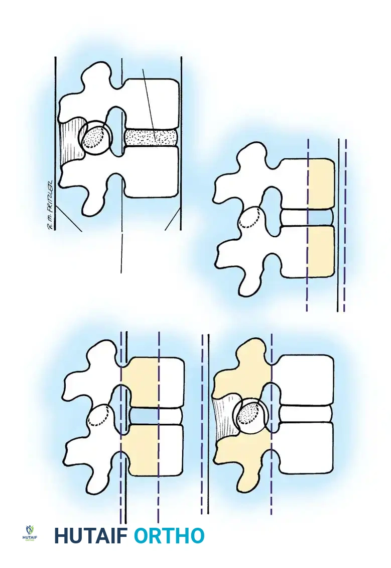
The classification of thoracolumbar fractures has evolved over decades to better dictate surgical decision-making. Nicoll initially described these fractures simply as stable or unstable. Holdsworth expanded this into a five-group classification based on the mechanism of injury:
1. Pure Flexion: Causes a stable wedge compression fracture.
2. Flexion and Rotation: Produces an unstable fracture-dislocation with rupture of the posterior ligamentous complex (PLC), separation of spinous processes, a "slice" fracture near the upper border of the lower vertebra, and facet dislocation.
3. Extension: Causes rupture of the intervertebral disc and anterior longitudinal ligament (ALL), often with an avulsion fracture. These typically reduce spontaneously and are stable in flexion.
4. Vertebral Compression: Forces the nucleus pulposus into the vertebral body, causing a burst fracture. If ligaments remain intact, this comminuted fracture may be stable.
5. Shearing: Results in whole-vertebra displacement and highly unstable fractures of the articular processes or pedicles.
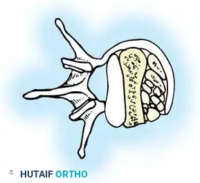
The Denis Three-Column Concept
Kelly and Whitesides originally described the spine as a two-column weight-bearing structure. Denis revolutionized spinal biomechanics by introducing the three-column concept, based on extensive CT evaluations of thoracolumbar injuries.
- Anterior Column: Comprises the ALL, the anterior half of the vertebral body, and the anterior portion of the anulus fibrosus.
- Middle Column: Consists of the posterior longitudinal ligament (PLL), the posterior half of the vertebral body, and the posterior aspect of the anulus fibrosus.
- Posterior Column: Includes the neural arch, ligamentum flavum, facet capsules, and interspinous/supraspinous ligaments.
Denis established that instability occurs when two or more columns fail under axial compression, distraction, or translation.
The McAfee Classification
McAfee et al. further refined this by focusing on the failure mechanism of the middle osteoligamentous complex:
1. Wedge Compression Fractures: Isolated anterior column failure (forward flexion). Rarely causes neurological deficit unless multiple levels are involved.
2. Stable Burst Fractures: Anterior and middle columns fail under compressive load; posterior elements remain intact.
3. Unstable Burst Fractures: Anterior and middle columns fail in compression, and the posterior column is disrupted (via compression, lateral flexion, or rotation). High risk of posttraumatic kyphosis and progressive neurological deficit.
4. Chance Fractures: Horizontal avulsion injuries caused by flexion around an axis anterior to the ALL. The entire vertebra fails in tension.
5. Flexion-Distraction Injuries: The flexion axis is posterior to the ALL. The anterior column fails in compression, while the middle and posterior columns fail in tension. Highly unstable due to PLC disruption.
6. Translational Injuries: Total disruption of the neural canal with shear failure across all three columns.
Thoracolumbar Injury Classification and Severity Score (TLICS)
Vaccaro et al. proposed the TLICS system to standardize operative indications. The score evaluates three critical domains:
1. Fracture Mechanism (Morphology)
* Compression fracture: 1 point
* Burst fracture: 1 point
* Translation/rotation: 3 points
* Distraction: 4 points
2. Neurological Status
* Intact: 0 points
* Nerve root injury: 2 points
* Cord/conus medullaris (incomplete): 3 points
* Cord/conus medullaris (complete): 2 points
* Cauda equina: 3 points
3. Posterior Ligamentous Complex (PLC) Integrity
* Intact: 0 points
* Suspected/Indeterminate: 2 points
* Injured: 3 points
Clinical Pearl: A total TLICS score of ≤ 3 indicates nonoperative management. A score of ≥ 5 is a strong indication for surgery. A score of 4 represents a clinical gray area where treatment is dictated by comorbidities, polytrauma status, and surgeon preference.
Indications and Timing of Surgery
The timing of surgical intervention in spinal cord injuries remains a topic of intense academic debate.
* Progressive Neurological Deficit: Universally accepted as an absolute indication for emergency decompression.
* Complete or Static Incomplete Injuries: Some authors advocate delaying surgery to allow cord edema to resolve, while others favor immediate stabilization.
Recent literature strongly supports early intervention. Mirza et al. demonstrated that decompression and stabilization within 72 hours of injury are not associated with higher complication rates and may improve neurological recovery while decreasing hospital length of stay. Chipman et al. corroborated this, finding that polytrauma patients with high Injury Severity Scores (ISS) who underwent early thoracolumbar surgery experienced fewer complications and shorter hospitalizations compared to delayed cohorts, despite requiring longer periods of mechanical ventilation.
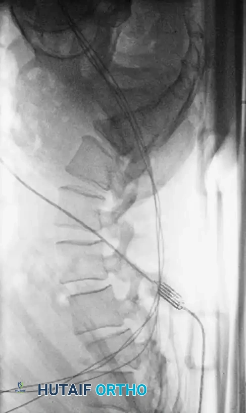
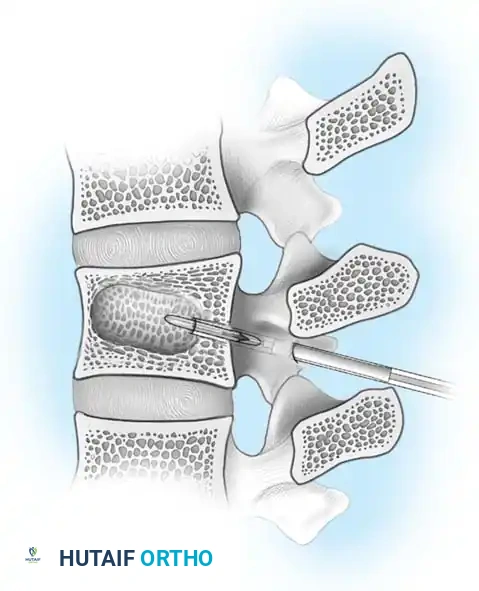
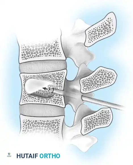
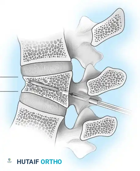
Principles of Spinal Decompression
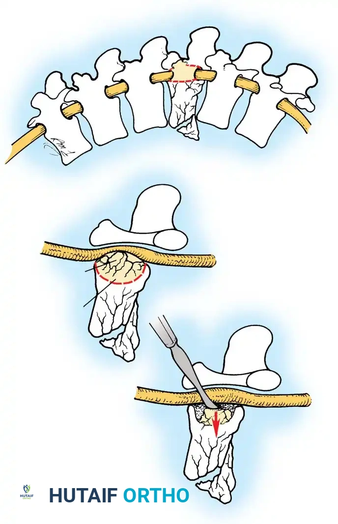
Compression of neural elements by retropulsed bone fragments can be addressed via two primary modalities:
- Indirect Decompression (Ligamentotaxis): Utilizes posterior distraction instrumentation and an intact PLL to pull retropulsed fragments out of the spinal canal. This is highly effective if performed acutely (< 72 hours). However, if surgery is delayed, fracture consolidation renders indirect reduction ineffective.
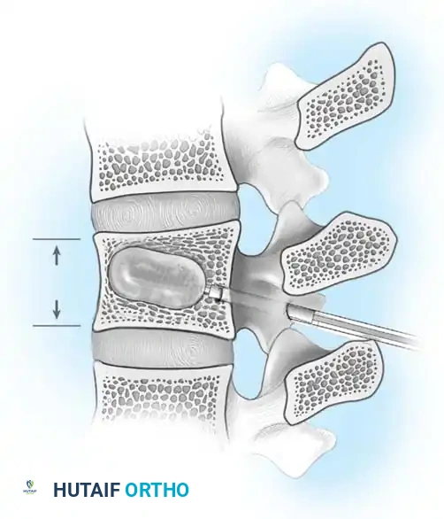
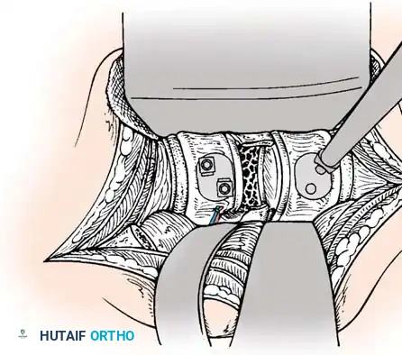
- Direct Decompression: Achieved via an anterior corpectomy or a posterolateral approach (e.g., transpedicular or costotransversectomy). This is mandatory for severely comminuted fractures where multiple bone fragments have breached the canal and cannot be reduced by ligamentotaxis alone.
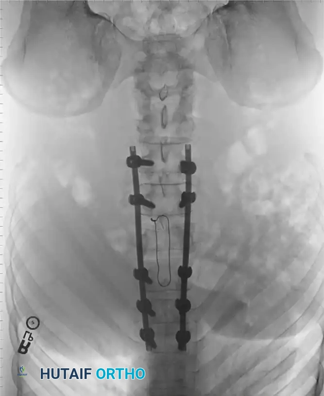
Surgical Technique: Posterior and Anterior Stabilization
Depending on the fracture morphology, surgeons may employ posterior pedicle screw constructs, anterior plating, or a combined 360-degree approach.
Posterior Exposure and Instrumentation
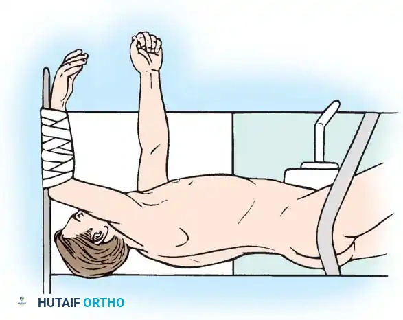
The patient is positioned prone on a radiolucent Jackson table. Neuromonitoring (SSEPs and MEPs) is established. A standard midline posterior approach is utilized, carefully preserving the facet capsules of adjacent uninjured levels.
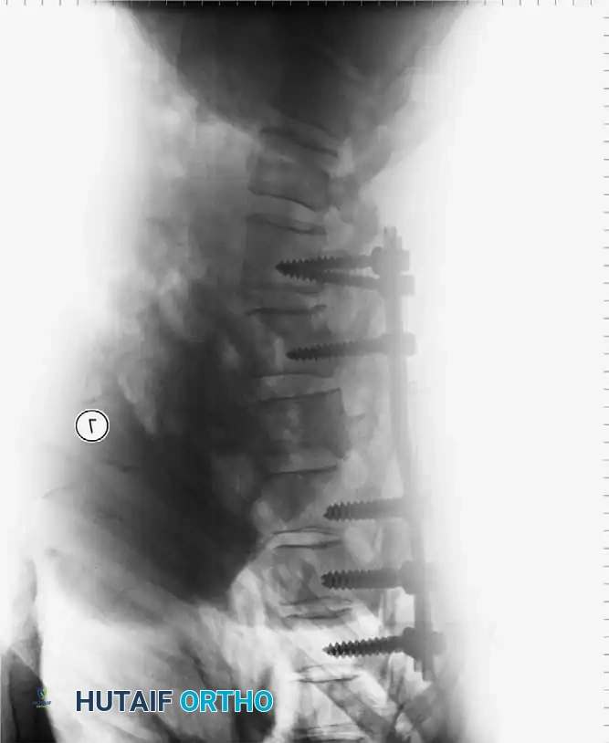
Pedicle screws are inserted under fluoroscopic or navigation guidance. The trajectory must respect the anatomical convergence of the pedicles, which varies from the thoracic to the lumbar spine.
Following screw placement, rods are contoured to restore physiological sagittal alignment (thoracic kyphosis or lumbar lordosis). Distraction or compression forces are applied based on the fracture pattern (e.g., compression for tension-band failures, distraction for burst fractures undergoing ligamentotaxis).
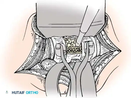
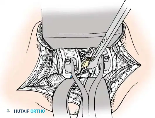
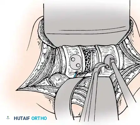
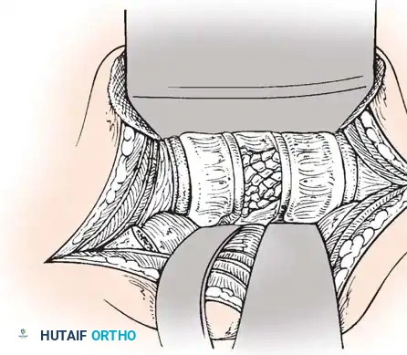
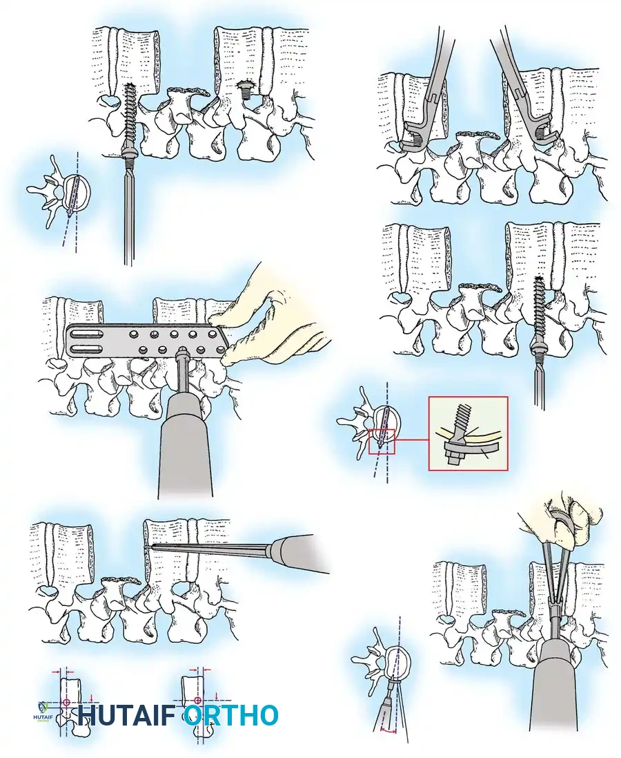
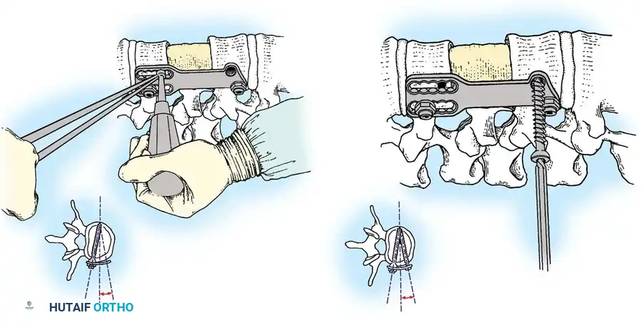
Anterior Plating Technique (Technique 35-16)
When anterior column reconstruction is required (e.g., post-corpectomy), anterior plating provides rigid stabilization.
- Measurement and Selection: Measure the distance between the middle of the cranial vertebra and the middle of the caudal vertebra to be included in the fixation. Use this caliper measurement to select the appropriate plate length.
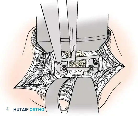
- Contouring: If necessary, use a plate bender to conform the plate to the patient's specific spinal anatomy. Make several slight bends along the length of the plate and between the screw holes to obtain a consistent radius of curvature.
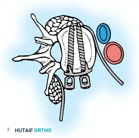
- Positioning: Using a plate holder, place the plate on the vertebral column in the optimal anatomical position.
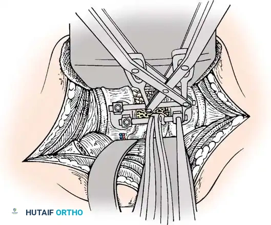
- Temporary Fixation: Temporarily fix the plate with small pins screwed into the cortical wall. Insert these self-cutting pins diagonally through the screw holes to obtain sufficient provisional stability.
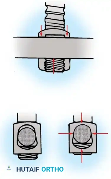
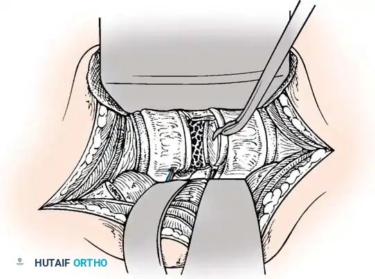
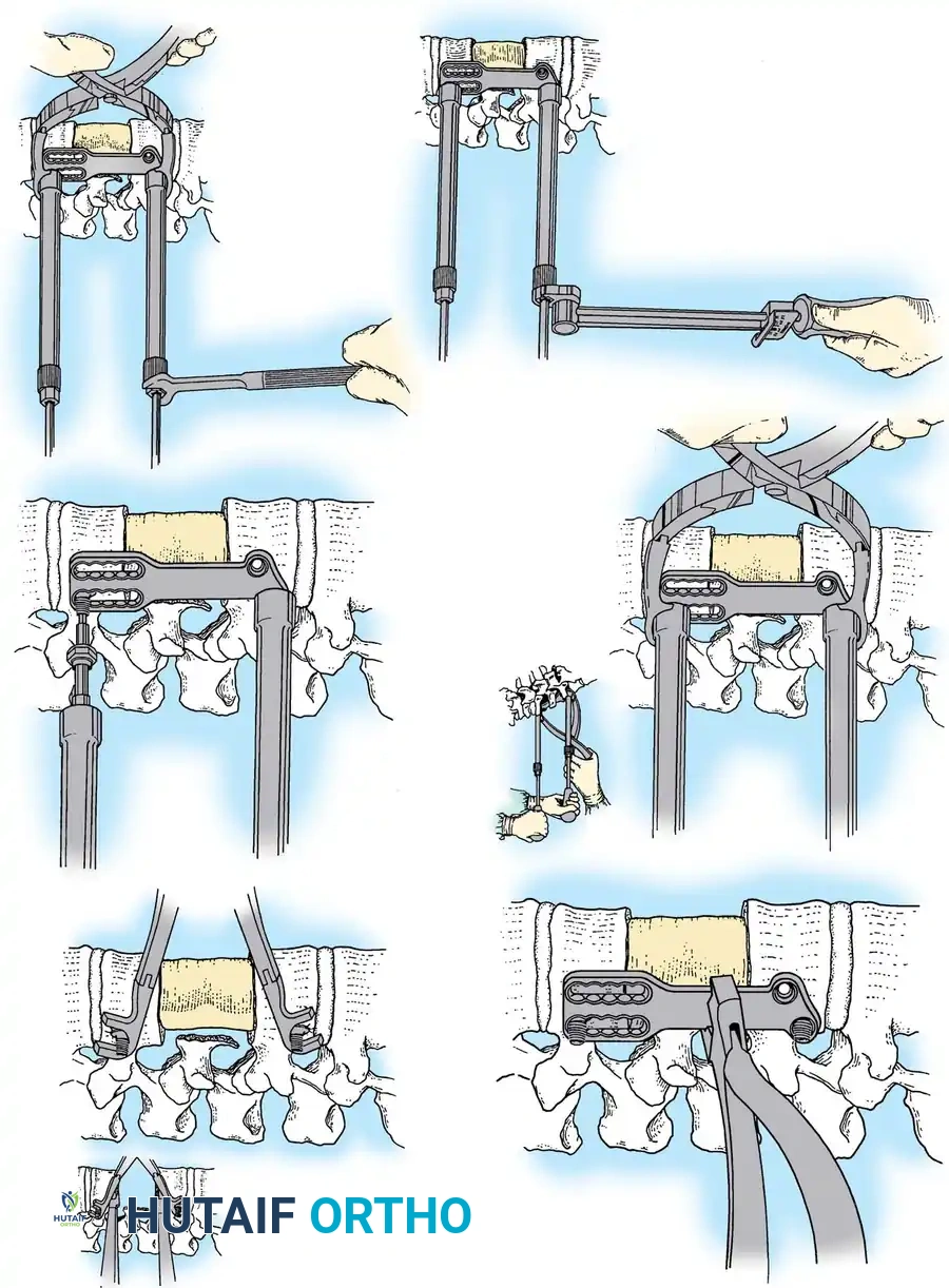
- Drilling: Place the drill guide on the plate. The guide limits pilot holes to the orientation of the integrated blocking ring (0 to ± 10 degrees sagittally and 6 degrees axially). Use the appropriate drill bit (10 mm, 12 mm, 14 mm, 16 mm, or 18 mm) to prepare the pilot hole.
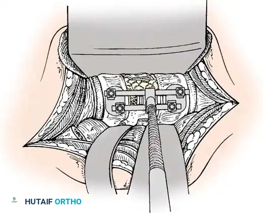
- Screw Insertion: While tapping is an option, modern screws are typically self-tapping. Insert the 4.0-mm or 4.5-mm screws into the pilot holes. Tighten until locked into the plate, ensuring the locking mechanism (washer) fully covers the screw head.
- Graft Securing: If a corpectomy and structural grafting were performed, secure the graft to the plate using standard 4-mm screws placed in the intermediary screw holes.
- Closure: Thoroughly irrigate the wound and close in layers over a subfascial drain.
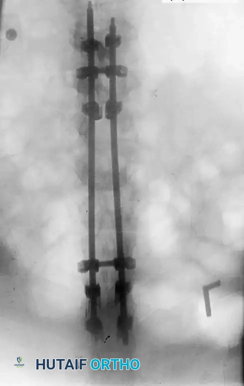
Postoperative Protocol and Rehabilitation
Rigid internal fixation allows for early mobilization, mitigating the systemic complications of prolonged bed rest (e.g., DVT, pneumonia, decubitus ulcers).
- Orthosis: Depending on construct rigidity and bone quality, patients may wear an external support, such as a Thoracolumbosacral Orthosis (TLSO) or a hard collar (if cervical extension is involved), for 6 to 12 weeks pending graft consolidation.
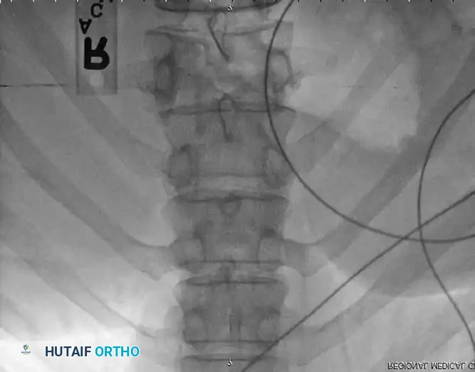
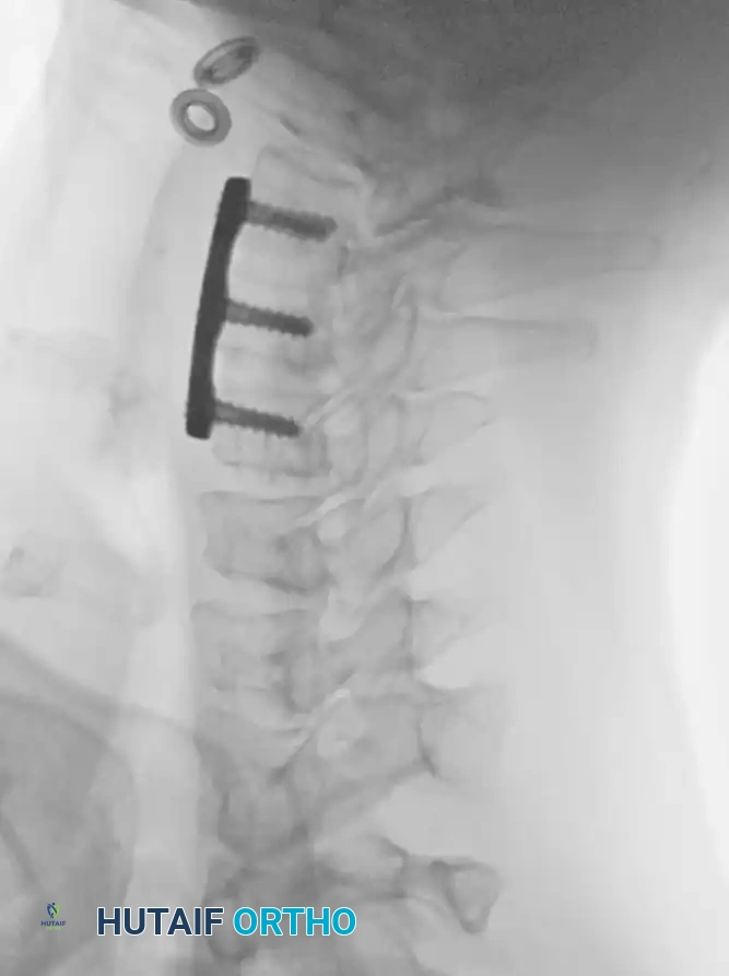
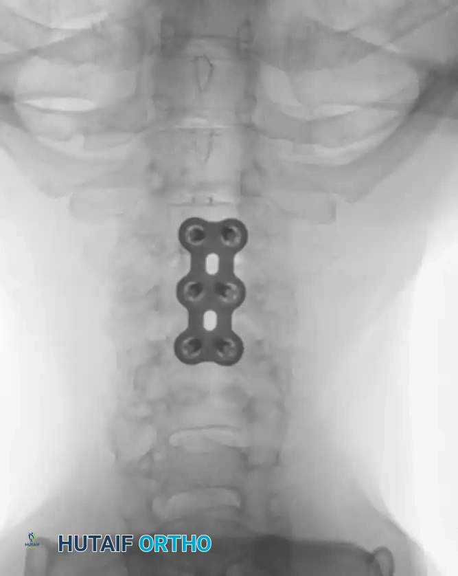
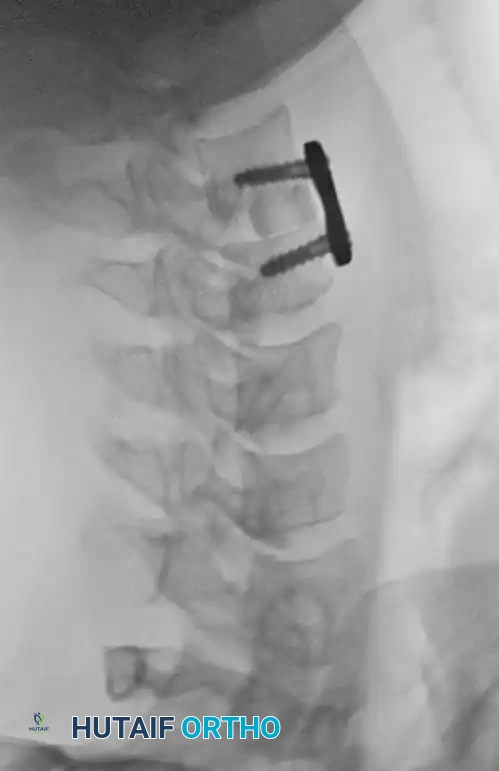
- Radiographic Evaluation: Serial plain radiographs (AP and Lateral) should be obtained at 2, 6, and 12 weeks, and subsequently at 6 and 12 months to monitor for hardware failure, loss of correction, and progression
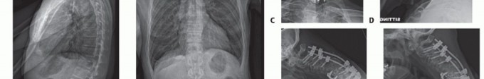
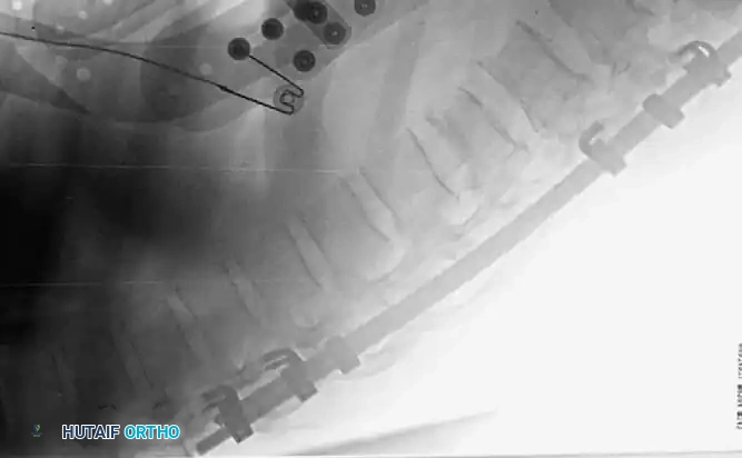
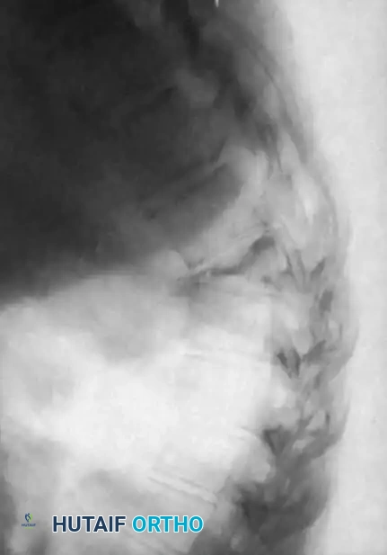
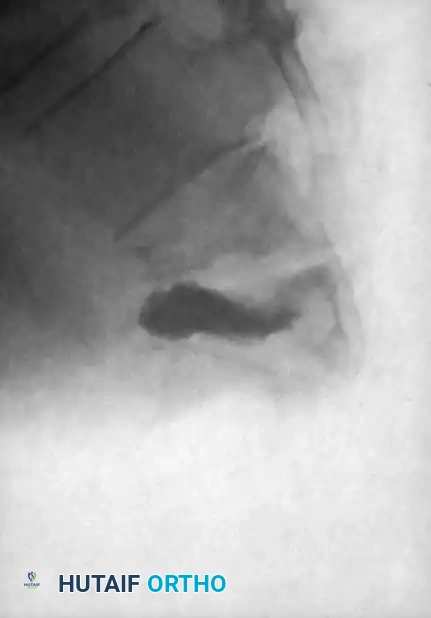
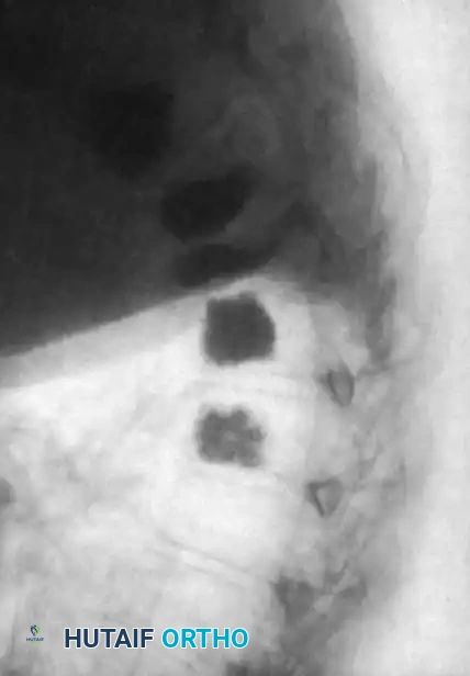
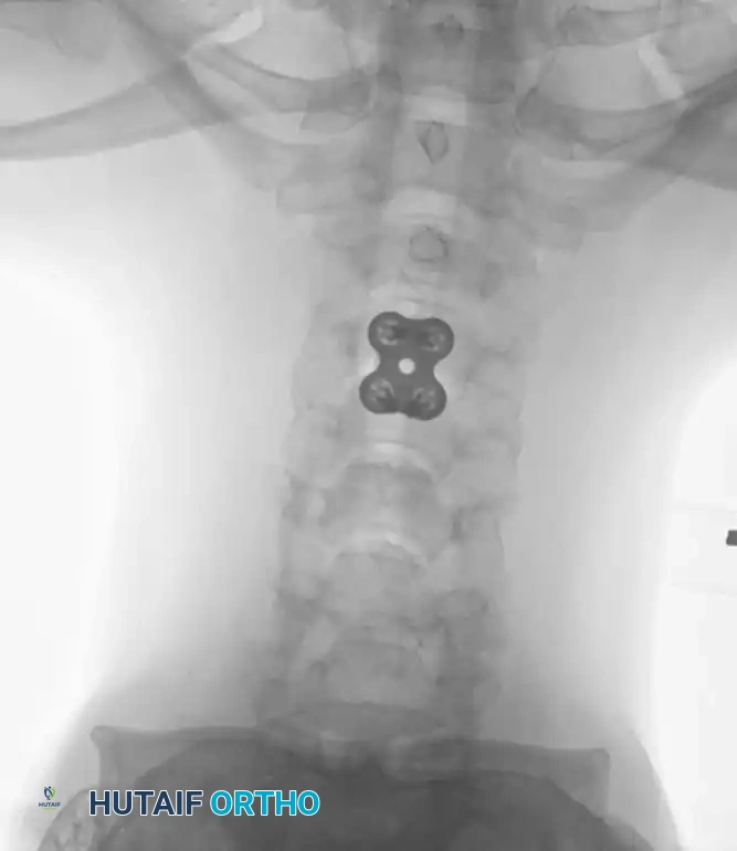
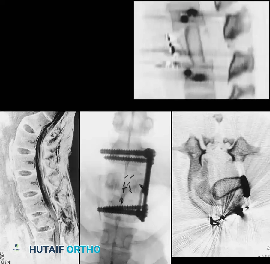
Associated Surgical & Radiographic Imaging
📚 Medical References
- thoracolumbar fractures, Contemp Orthop 20:285, 1990.
- Kolenda H, Steffens H, Gefeller O, et al: Critical levels of spinal cord blood fl ow and duration of ischemia for the acute recovery of segmental spinal cord responses in cats, J Spinal Disord 10:288, 1997.
- Kothe R, O’Holleran JD, Liu W, et al: Internal architecture of the thoracic pedicle: an anatomic study, Spine 21:264, 1996.
- Louis R: Single-staged posterior lumbosacral fusion by internal fi xation with screw plates. Paper presented at the annual meeting of the International Society for the Study of the Lumbar Spine, Sydney, Australia, 1985.
- Lu J, Ebraheim NA, Yang H, et al: Anatomic bases for anterior spinal surgery: surgical anatomy of the cervical vertebral body and disc space, Surg Radiol Anat 21:235, 1999.
- Mazzara JT, Fielding JW: Effect of C1-C2 rotation on canal size, Clin Orthop Relat Res 237:115, 1988.
- McCormick PC: Retropleural approach to the thoracic and thoracolumbar spine, Neurosurgery 37:908, 1995.
- Mirkovic SR, Schwartz DG, Glazier KD: Anatomic considerations in lumbar posterolateral percutaneous procedures, Spine 20:1965, 1995.
- Oh SH, Perin NI, Cooper PR: Quantitative three-dimensional anatomy of the subaxial cervical spine: implication for anterior spinal surgery, Neurosurgery 38:1139, 1996.
- Panjabi MM, O’Holleran JD, Crisco JJ III, et al: Complexity of the thoracic spine pedicle anatomy, Eur Spine J 6:19, 1997.
- Prescher A: Anatomy and pathology of the aging spine, Eur J Radiol 27:181, 1998.
- Robertson PA, Stewart NR: The radiologic anatomy of the lumbar and lumbosacral pedicles, Spine 25:709, 2000.
- Roy-Camille R, Saillant G, Mazel CH: Plating of thoracic, thoracolumbar, and lumbar injuries with pedicle screw plates, Orthop Clin North Am 17:147, 1986.
- Saillant G: Anatomic study of vertebral pedicles: surgical application, Rev Chir Orthop 62:151, 1976.
- Vraney RT, Phillips FM, Wetzel FT, et al: Peridiscal vascular anatomy of the lower lumbar spine: an endoscopic perspective, Spine 24:2183, 1999.
- Watkins RG: The spine in sports, St Louis, 1996, Mosby. Xu R, Ebraheim NA, Robke J, et al: Radiologic and anatomic evaluation of the anterior sacral foramens and nerve grooves, Spine 21:407, 1996.
- Zindrick MR, Wiltse LL, Doornik A, et al: Analysis of the morphometric characteristics of the thoracic and lumbar pedicles, Spine 12:160, 1987.
- Zindrick MR, Wiltse LL, Widell EH, et al: A biomechanical study of intrapeduncular screw fi xation in the lumbosacral spine, Clin Orthop Relat Res 203:99, 1986.
- Surgical Approaches Bailey RW, Badgley CE: Stabilization of the cervical spine by anterior fusion, J Bone Joint Surg 42A:565, 1960.
- Barone GW, Eidt JF, Webb JW, et al: The anterior extrapleural approach to the thoracolumbar junction revisited, Am Surg 64:372, 1998.
- Bell GR: The anterior approach to the cervical spine, Neuroimaging Clin N Am 5:465, 1995.
- Bohlman HH, Ducker TB, Lucas JT: Spine and spinal cord injuries. In Rothman RH, Simeone FA, eds: The spine, 2nd ed, Philadelphia, 1982, Saunders. Bohlman HH, Eismont FJ: Surgical techniques of anterior decompression and fusion for spinal cord injuries, Clin Orthop Relat Res 154:57, 1981.
- Bonney G, Williams JPR: Transoral approach to the
You Might Also Like