Transverse Ligament Rupture: Recognizing & Treating This Serious Injury
Key Takeaway
We review everything you need to understand about Transverse Ligament Rupture: Recognizing & Treating This Serious Injury. A **transverse ligament rupture** is a rare, often fatal C1-C2 spinal injury usually seen in older adults, caused by forced flexion. It presents with symptoms from severe neck pain to neurological compromise. Diagnosis involves CT, MRI, or specific atlantoaxial measurements. Initial treatment often includes halo immobilization, while C1-C2 fusion is indicated for tears without avulsion or chronic instability.
Introduction & Epidemiology
Rupture of the transverse ligament of the atlas represents a critical injury to the craniocervical junction, often resulting in atlantoaxial instability with potentially devastating neurological consequences. While historically considered rare and frequently fatal, advancements in prehospital care, imaging modalities, and surgical techniques have improved diagnosis and management, leading to better outcomes. However, the injury remains serious and demands a high index of suspicion.
The transverse ligament is the primary stabilizer against anterior translation of C1 (atlas) on C2 (axis). Its rupture permits pathological anterior displacement of the atlas, encroaching upon the spinal canal and placing the cervicomedullary junction at risk.
Epidemiologically, transverse ligament ruptures are predominantly observed in older age groups, typically individuals in their 50s to 60s. This demographic predisposition is often attributed to age-related degenerative changes in ligaments and bone, which may render the structures more susceptible to failure under stress, or to specific injury mechanisms more common in this population (e.g., falls). The classic mechanism of injury is a forced flexion moment to the head and neck, often encountered in motor vehicle accidents, falls from height, or direct trauma. However, hyperextension injuries can also contribute to instability by damaging the posterior elements, although direct transverse ligament rupture from hyperextension is less common.
The clinical presentation can vary widely, from severe, intractable neck pain exacerbated by movement to overt signs of neurological compromise, including quadriparesis, sensory deficits, or even sudden death due to brainstem compression. A subset of patients may present with vague symptoms such as occipital headaches or cervicalgia, underscoring the need for meticulous evaluation in patients with a history of cervical trauma. Therefore, recognizing the injury early and initiating appropriate management is paramount to preventing irreversible neurological damage.
Surgical Anatomy & Biomechanics
A thorough understanding of the atlantoaxial complex (C1-C2) anatomy and its intricate ligamentous stabilizers is fundamental to managing transverse ligament ruptures.
C1-C2 Bony Anatomy
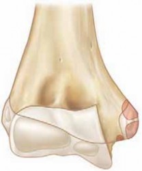
- Atlas (C1): A ring-shaped vertebra composed of an anterior arch, a posterior arch, and two lateral masses connected by these arches. It lacks a vertebral body and spinous process. The superior articular facets articulate with the occipital condyles, while the inferior articular facets articulate with the superior articular facets of C2. The anterior arch forms a facet for articulation with the odontoid process.
- Axis (C2): Characterized by the dens (odontoid process) projecting superiorly from its vertebral body. The dens articulates with the anterior arch of C1 and is embraced posteriorly by the transverse ligament. The superior articular facets are located lateral to the dens and articulate with C1. The C2 lamina and spinous process provide crucial anchors for muscle attachments and surgical fixation.
Ligamentous Stabilizers of the Atlantoaxial Joint
The stability of the atlantoaxial joint relies heavily on a complex network of ligaments:
1.
Transverse Ligament:
The primary restraint to anterior translation of C1 on C2. It is a strong, fibrous band stretching between the medial tubercles on the lateral masses of C1. It holds the odontoid process firmly against the anterior arch of C1. The transverse ligament, along with its superior and inferior longitudinal bands, forms the
Cruciform Ligament
.
*
Superior Longitudinal Band:
Extends from the transverse ligament to the clivus.
*
Inferior Longitudinal Band:
Extends from the transverse ligament to the posterior body of C2.
2.
Alar Ligaments:
Paired ligaments originating from the apex and sides of the odontoid process, extending superolaterally to the medial aspect of the occipital condyles. They primarily limit axial rotation and lateral bending of the head and C1 on C2.
3.
Apical Ligament:
A small, weak ligament connecting the apex of the odontoid to the anterior rim of the foramen magnum. Its contribution to stability is minor.
4.
Tectorial Membrane:
A broad, strong ligament that is the superior continuation of the posterior longitudinal ligament. It covers the posterior aspect of the dens and the cruciform ligament, extending superiorly to attach to the clivus. It provides secondary stability against both flexion and extension.
5.
Accessory Atlantoaxial Ligaments:
These extend from the posterior body of C2 to the lateral masses of C1, providing additional stability.
Biomechanics of Atlantoaxial Instability
The transverse ligament is responsible for approximately 80-90% of the resistance to anterior translation of C1 relative to C2. A rupture compromises this primary restraint, leading to excessive anterior atlantoaxial interval (ADI).
*
Normal ADI:
In adults, the ADI (distance between the posterior aspect of the anterior arch of C1 and the anterior aspect of the odontoid) should not exceed 3 mm. In children, up to 4-5 mm is considered normal due to greater ligamentous laxity.
*
Pathological ADI:
An ADI greater than 3 mm in adults strongly suggests transverse ligament compromise. An ADI exceeding 5 mm in adults, especially in conjunction with findings consistent with transverse ligament rupture, additionally implies concomitant disruption of the alar ligaments, significantly increasing instability. Atlantoaxial offset greater than 6.9 mm on odontoid radiographs is also a critical indicator.
*
Mechanism of Injury:
Forced flexion results in increased strain on the posterior atlantoaxial ligaments, including the transverse ligament. Depending on the vector and magnitude of force, the ligament can fail through mid-substance tearing (Type I rupture, per Dickman classification) or by avulsing a fragment of bone from its attachment site on the lateral mass of C1 (Type II rupture).
*
Spinal Cord Compromise:
When C1 translates excessively anteriorly, the posterior arch of C1 and the lateral masses can impinge directly on the spinal cord. The space available for the cord (SAC) decreases, risking neurological deficit. The normal SAC at C1-C2 is approximately 13-14 mm. A SAC less than 13 mm (often measured as the distance from the posterior arch of C1 to the posterior aspect of the odontoid) indicates potential cord compression.
Indications & Contraindications
Accurate diagnosis and appropriate classification are crucial for determining the optimal treatment strategy.
Diagnostic Criteria
-
Radiographic Evaluation:
- Lateral Cervical Radiographs: Assessment of the Atlantoaxial Interval (ADI). An ADI > 3 mm in adults is highly suspicious for transverse ligament rupture. An ADI > 5 mm suggests combined transverse and alar ligament failure.
- Odontoid View Radiograph: Atlantoaxial offset > 6.9 mm. This can indicate lateral displacement or rotation in addition to anterior translation.
- Flexion-Extension Views: While useful for dynamic instability assessment, these should be performed with extreme caution and under direct clinical supervision in acute trauma settings, particularly if initial static imaging reveals significant instability or neurological deficit. They are primarily used in chronic or equivocal cases.
-
Computed Tomography (CT) Scan:
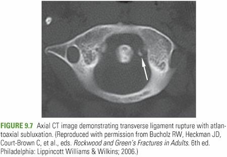
- Bony Avulsion: Direct visualization of an avulsed lateral mass fragment of C1 (often referred to as a "fragment of C1 lateral mass" or "os odontoideum" in some contexts, though the latter is a developmental anomaly) is diagnostic of a Type II transverse ligament rupture.
- Atlantoaxial Alignment: Excellent for assessing bony alignment and evaluating for other concomitant fractures.
- Vertebral Artery Evaluation: CT angiography (CTA) is crucial for assessing the course and patency of the vertebral arteries, especially prior to C1 lateral mass or C2 pedicle screw placement, given their proximity.
-
Magnetic Resonance Imaging (MRI):
- Direct Visualization: MRI is the gold standard for visualizing soft tissue injuries. Direct visualization of a torn transverse ligament (Type I rupture) or associated edema/hematoma at the ligamentous insertion site (Type II rupture) confirms the diagnosis.
- Spinal Cord Assessment: Essential for evaluating for spinal cord edema, contusion, or compression.
- Alar Ligament Integrity: MRI can also assess the integrity of the alar ligaments and tectorial membrane, providing a comprehensive understanding of the craniocervical ligamentous complex.
Classification (Dickman Classification)
- Type I Rupture: Mid-substance tear of the transverse ligament. This type has poor healing potential due to the lack of direct blood supply within the ligament substance.
- Type II Rupture: Avulsion of the transverse ligament from its bony insertion on the lateral mass of C1, often with an associated osseous fragment. This type has a higher potential for healing with adequate immobilization, provided the bony fragment can unite.
Indications for Treatment
| Feature | Non-Operative Treatment | Operative Treatment (Posterior C1-C2 Fusion) |
|---|---|---|
| Type of Rupture | Dickman Type II (bony avulsion) | Dickman Type I (mid-substance tear) |
| Stability | Stable (minimal ADI, no progressive instability) | Unstable (ADI > 3-5mm, progressive instability on dynamic imaging) |
| Neurological Status | Intact, no signs of cord compression | Neurological deficit (new or progressive), signs of cord compression |
| Ligament Integrity | Isolated Type II, potentially stable alar ligaments | Combined ligamentous injuries (e.g., transverse + alar ligament rupture) |
| Chronicity | Acute injury with good potential for healing | Chronic instability, persistent pain, pseudarthrosis following non-op |
| Reduction | Reducible and maintainable in halo immobilization | Irreducible instability, failure of halo reduction/maintenance |
Specific Operative Indications:
*
Dickman Type I tears:
Due to low healing potential, fusion is generally indicated.
*
Dickman Type II tears:
* Failure of non-operative treatment (e.g., non-union of the avulsed fragment, persistent instability or pain despite adequate halo immobilization).
* Initial irreducible instability, or instability that cannot be maintained with external orthosis.
* Associated significant neurological deficit or spinal cord compromise.
* Concomitant injury to the alar ligaments or tectorial membrane, leading to global atlantoaxial instability.
*
Chronic Atlantoaxial Instability:
Resulting from untreated or unsuccessfully treated transverse ligament rupture, with persistent pain, neurological symptoms, or objective instability.
Contraindications for Surgical Intervention
- Severe Comorbidities: Patients with severe medical comorbidities that preclude general anesthesia and major spinal surgery.
- Active Infection: Local or systemic infection that would contraindicate hardware implantation.
- Non-reducible Instability (Absolute): Inability to reduce the atlantoaxial subluxation, even with preoperative traction, making safe screw placement impossible without risking neurological injury. While rare, this may necessitate alternative approaches or staged procedures.
- Pre-existing Atlantoaxial Fusion: Not a contraindication to fusion per se, but implies a complex history and possibly an alternative etiology for new instability.
Pre-Operative Planning & Patient Positioning
Meticulous pre-operative planning is essential for a safe and successful C1-C2 fusion.
Pre-Operative Assessment
- Neurological Examination: A comprehensive baseline neurological examination is critical, documenting any motor, sensory, or reflex deficits. This serves as a reference for intraoperative and postoperative monitoring.
-
Imaging Review:
- CT Scan: Detailed analysis of bony anatomy, fracture patterns, vertebral artery foramina (transverse foramina of C1 and C2), and pedicle morphology. 3D reconstructions are invaluable for understanding complex deformities and planning screw trajectories.
- CT Angiography (CTA): Highly recommended to delineate the course of the vertebral arteries, especially within the C1 lateral mass and C2 pedicles. Aberrant courses or high-riding vertebral arteries can significantly impact screw placement strategy.
- MRI: Confirmation of ligamentous injury, assessment of spinal cord integrity (edema, compression), and evaluation of other soft tissue structures.
-
Reduction Attempt (if indicated):
For significantly displaced instabilities, especially Type II ruptures or Type I with substantial ADI, initial halo traction may be employed.
- Technique: Gradual application of traction (starting with 5-10 lbs, increasing by 2-5 lbs increments every few hours) while meticulously monitoring neurological status and serial lateral radiographs. The goal is to achieve reduction without overdistraction.
- Monitoring: Continuous neurological checks are paramount. If reduction is achieved and maintained, it simplifies intraoperative maneuver and reduces the risk of iatrogenic injury. Irreducible subluxation after adequate traction warrants careful consideration and potentially different surgical strategies.
Patient Positioning
- General Anesthesia: Standard anesthetic induction. Endotracheal intubation (often fiberoptic-guided or awake intubation in cases of severe instability) is performed with extreme care to avoid exacerbating cervical motion.
- Neuromonitoring: Somatosensory Evoked Potentials (SSEPs) and Motor Evoked Potentials (MEPs) are standard for all posterior cervical spine surgeries, providing real-time feedback on spinal cord function.
-
Prone Position:
The patient is carefully turned to the prone position on a radiolucent operating table.
- Head Fixation: The head is secured in a Mayfield head clamp or similar skull traction device. This allows for rigid cranial fixation and subtle adjustments in head position for optimal surgical exposure and reduction.
- Cervical Alignment: The neck should be maintained in a neutral to slight flexion position to facilitate posterior element exposure and aid in reduction if needed. Avoid extreme flexion or extension.
- Pressure Point Padding: Meticulous padding of all pressure points (cheeks, eyes, elbows, knees, feet) is essential to prevent nerve compression or skin breakdown. A shoulder roll or chest rolls can help ensure slight cervical flexion and prevent undue pressure on the brachial plexus.
- Surgical Site Preparation: The posterior cervical region is prepped and draped in a sterile fashion, extending from the occiput to the upper thoracic spine.
- Fluoroscopy/Navigation Setup: Intraoperative fluoroscopy (anteroposterior and lateral views) or 3D navigation (O-arm, C-arm based) is set up and calibrated. Navigation is highly recommended, especially with complex anatomy or high-riding vertebral arteries, to improve screw placement accuracy and reduce the risk of neurovascular injury.
Detailed Surgical Approach / Technique: Posterior C1-C2 Fusion
Posterior C1-C2 fusion remains the gold standard for stabilizing atlantoaxial instability secondary to transverse ligament rupture, particularly for Dickman Type I tears and failed non-operative management of Type II tears. The most common technique involves C1 lateral mass and C2 pedicle/pars screw fixation with rod construct.
1. Incision and Exposure
- Midline Incision: A straight midline incision is made from the external occipital protuberance to the C3-C4 spinous process level.
- Subperiosteal Dissection: The trapezius and nuchal ligament are incised in the midline. Subperiosteal dissection proceeds laterally to expose the posterior arch of C1, the lamina and spinous process of C2, and the lateral masses of C1 and articular facets of C2.
- Muscle Reflection: The semispinalis capitis and rectus capitis posterior major muscles are carefully reflected laterally from the midline.
-
Key Anatomical Landmarks:
- C1 Posterior Arch: Palpate its smooth, broad surface.
- C2 Spinous Process: The largest of the cervical spinous processes, typically bifid.
- C2 Lamina: Exposed superior and inferior to the spinous process.
- Vertebral Artery: This is the most critical structure to protect. On C1, the vertebral artery courses in a groove on the superior surface of the posterior arch, approximately 1.5 cm lateral to the midline. On C2, it passes through the transverse foramen and then turns superomedially to enter the C1 transverse foramen. Extreme caution is needed during lateral dissection on C1 and C2. The C2 ganglion and nerve root lie just inferior to the C1-C2 joint, which also needs careful retraction or protection.
2. Reduction of Atlantoaxial Subluxation
- If not achieved pre-operatively with halo traction, gentle intraoperative reduction can be performed. This involves subtle manipulation of the head (guided by Mayfield) and direct pressure on the posterior arch of C1, often combined with light traction, while continuously monitoring neuromonitoring signals.
- Fluoroscopy (lateral view) is used to confirm adequate reduction, ensuring an appropriate ADI and alignment.
3. Instrumentation
Modern C1-C2 fusion typically involves posterior screw fixation: C1 lateral mass screws and C2 pedicle or pars screws, connected by contoured rods.
A. C1 Lateral Mass Screw Placement
- Entry Point: The entry point for the C1 lateral mass screw is typically located at the junction of the inferior margin of the C1 posterior arch and the midpoint of the lateral mass (relative to its medial and lateral borders). It is generally just inferior and lateral to the midpoint of the posterior arch.
- Trajectory: The screw should be directed anteriorly (parallel to the transverse ligament and articular surface of C1) and slightly medially (5-10 degrees convergence) and slightly superiorly (10-15 degrees cephalad). This trajectory aims to engage the C1 lateral mass maximally, avoiding the vertebral artery anteriorly and laterally, and the spinal canal medially.
- Probe and Tap: A small burr is used to create a cortical breach. A ball-tipped probe is used to confirm the absence of cortical breaches in all directions. The screw hole is then tapped, usually to the length of the planned screw.
- Screw Length: Typically 30-36 mm, depending on patient anatomy. Pre-operative CT measurements are critical.
- Cautions: The vertebral artery is directly anterior and anterolateral to the C1 lateral mass. Inferiorly, the C2 nerve root and ganglion are in close proximity. Careful blunt dissection and protection of the C2 ganglion are necessary.
B. C2 Pedicle Screw Placement (Preferred in most cases)
- Entry Point: The entry point for the C2 pedicle screw is located at the junction of the lateral margin of the C2 lamina and the superior aspect of the C2 inferior articular process. It is typically just superolateral to the C2-C3 facet joint.
- Trajectory: The screw is directed approximately 20-30 degrees medially (convergent towards the midline) and 20-30 degrees cranially (cephalad, aiming towards the superior anterior aspect of the C2 body). The medial trajectory is crucial to keep the screw within the pedicle and away from the vertebral artery, which lies lateral and often anterior to the pedicle, running in the transverse foramen.
- Probe and Tap: After creating a cortical breach, a ball-tipped probe confirms the pedicle's integrity. Tapping is performed to the desired screw length.
- Screw Length: Typically 24-30 mm, depending on pedicle length and patient anatomy.
- Cautions: The vertebral artery is anterior and lateral to the pedicle. The C2 nerve root and ganglion are inferior to the entry point and must be protected. Pre-operative CTA is essential to identify high-riding vertebral arteries or unusually medialized arteries, which may necessitate alternative C2 fixation (e.g., C2 pars screw).
C. C2 Pars Screw Placement (Alternative to Pedicle Screw)
- Entry Point: Located just inferior and medial to the C1-C2 facet joint, at the base of the C2 superior articular process, lateral to the lamina.
- Trajectory: Directed anteromedially, similar to the pedicle screw, but with less medial angulation and a slightly more caudal inclination initially, aiming towards the C2 vertebral body.
- Advantages: May be safer in cases of high-riding vertebral artery or dysplastic C2 pedicles.
- Disadvantages: Shorter screw length compared to pedicle screws, potentially less pullout strength.
4. Rod Contouring and Fixation
- Rod Selection: Appropriately sized titanium or cobalt-chrome rods are selected.
- Rod Contouring: The rods are carefully contoured to connect the C1 lateral mass screws to the C2 pedicle/pars screws, matching the natural cervical lordosis. Slight compression across the C1-C2 joint can enhance stability and promote fusion.
- Secure Fixation: Locking caps are applied and securely tightened, ensuring a rigid construct. Intraoperative fluoroscopy confirms the final position of screws and rods.
5. Decortication and Bone Grafting
- Decortication: The posterior arch of C1 and the lamina and articular facets of C2 are thoroughly decorticated using a high-speed burr. This exposes cancellous bone, promoting bleeding and enhancing bone graft incorporation.
- Bone Grafting: Autogenous bone graft (local bone from the spinous processes and lamina, or iliac crest if a larger volume is needed) is typically applied over the decorticated surfaces of C1 and C2, bridging the C1-C2 posterior elements. Allograft (e.g., demineralized bone matrix, cancellous chips) can be used as an extender or substitute, though autograft remains the gold standard for robust fusion.
6. Closure
- The surgical site is irrigated thoroughly.
- Hemostasis is achieved.
- A surgical drain may be placed.
- The muscular layers, nuchal ligament, and subcutaneous tissues are closed in layers.
- Skin closure is performed.

Illustration: A typical posterior C1-C2 fusion construct, demonstrating C1 lateral mass screws and C2 pedicle screws connected by longitudinal rods, with bone graft often applied over decorticated surfaces.
Complications & Management
Posterior C1-C2 fusion, while effective, is technically demanding and carries potential risks. Awareness of these complications and strategies for prevention and management is critical.
Table of Common Complications and Management Strategies
| Complication | Incidence | Salvage / Management Strategy ## Transverse Ligament Rupture: Recognizing & Treating This Serious Injury
This document provides a comprehensive overview of transverse ligament ruptures, from initial presentation to long-term management strategies, catering to Orthopedic Surgeons, Residents, and Medical Students. The focus is on robust academic content, clinical pearls, and surgical indications/techniques.
Introduction & Epidemiology
Rupture of the transverse ligament of the atlas (traumatic C1-C2 instability) represents a critical and potentially devastating injury to the craniocervical junction. This ligament is the primary restraint against anterior translation of C1 on C2, safeguarding the cervicomedullary junction from compression. While historically considered a rare and often fatal event, improved understanding, advanced imaging, and modern surgical techniques have significantly improved diagnosis and management. However, the seriousness of the injury necessitates a high index of suspicion and prompt intervention.
Epidemiological data indicate a predilection for older age groups, typically individuals in their 50s and 60s. This demographic susceptibility is often attributed to age-related degenerative changes within the ligamentous structures and underlying bone, rendering them more vulnerable to traumatic forces. The most common mechanism of injury is forced flexion of the head and neck, frequently encountered in scenarios such as motor vehicle collisions, falls from height, or direct impact trauma. Less commonly, combined flexion-rotation or even hyperextension injuries can contribute to instability, particularly if other posterior ligamentous structures are simultaneously compromised.
The clinical presentation is highly variable, ranging from severe, localized neck pain and occipital headaches, exacerbated by movement, to acute neurological compromise including quadriparesis, sensory deficits, or even sudden cardiorespiratory arrest due to direct brainstem compression. Due to this spectrum of presentation, subtle signs in trauma patients, or even those presenting with vague cervicalgia following an injury, must prompt a thorough evaluation for potential craniocervical instability. Early and accurate diagnosis is paramount to prevent progressive neurological deterioration and optimize patient outcomes.
Surgical Anatomy & Biomechanics
A profound understanding of the intricate anatomy and biomechanics of the atlantoaxial complex (C1-C2) is non-negotiable for effective management of transverse ligament ruptures.
C1-C2 Bony Architecture
- Atlas (C1): This ring-like vertebra lacks a traditional vertebral body and spinous process. It comprises an anterior arch, a posterior arch, and two robust lateral masses that articulate superiorly with the occipital condyles and inferiorly with the superior articular facets of C2. The anterior arch features a posterior facet for articulation with the odontoid process.
- Axis (C2): The defining feature of C2 is the dens (odontoid process) , which projects superiorly from its vertebral body. The dens acts as a pivot around which C1 rotates. The superior articular facets of C2, located lateral to the dens, articulate with C1. The C2 lamina and bifid spinous process provide critical anatomical landmarks and anchor points for posterior muscle attachments and surgical fixation.
Ligamentous Stabilizers of the Atlantoaxial Joint
The stability of the atlantoaxial joint is synergistically maintained by a complex array of ligaments:
1.
Transverse Ligament of the Atlas:
This is the primary static stabilizer, preventing excessive anterior translation of C1 relative to C2. It is a thick, strong, fibrous band extending transversely between the medial tubercles on the lateral masses of C1. It holds the odontoid process firmly against the posterior aspect of the anterior arch of C1. The transverse ligament, along with its thinner
superior
and
inferior longitudinal bands
, forms the
Cruciform Ligament
.
* The
superior longitudinal band
ascends from the transverse ligament to the clivus.
* The
inferior longitudinal band
descends from the transverse ligament to the posterior body of C2.
2.
Alar Ligaments:
These paired, strong ligaments originate from the apex and superolateral aspects of the odontoid process. They extend obliquely superolaterally to attach to the medial aspects of the occipital condyles. Their primary function is to limit axial rotation and lateral bending of the head and C1 on C2.
3.
Apical Ligament:
A relatively weak fibrous cord connecting the apex of the odontoid to the anterior rim of the foramen magnum. Its contribution to overall stability is minimal.
4.
Tectorial Membrane:
This broad, robust ligament is the cephalad continuation of the posterior longitudinal ligament. It overlays the posterior aspect of the dens and the entire cruciform ligament, ascending to attach to the clivus. It provides secondary restraint against both flexion and extension movements.
5.
Accessory Atlantoaxial Ligaments:
These variable ligaments course from the posterior aspect of the C2 body to the lateral masses of C1, offering additional, though less significant, stability.
Biomechanics of Atlantoaxial Instability
The transverse ligament alone contributes an estimated 80-90% of the biomechanical resistance to anterior shear forces at the C1-C2 articulation. Its rupture fundamentally compromises this primary restraint, leading to an increased
Atlantoaxial Interval (ADI)
.
*
Normal ADI:
In neurologically intact adults, the distance between the posterior aspect of the anterior arch of C1 and the anterior cortical surface of the odontoid should not exceed 3 mm. In pediatric populations, an ADI of up to 4-5 mm may be considered within normal limits due to inherent ligamentous laxity.
*
Pathological ADI:
An ADI greater than 3 mm in adults is highly indicative of transverse ligament incompetence. An ADI exceeding 5 mm in adults suggests a more extensive injury, implying concomitant disruption of the alar ligaments and potentially the tectorial membrane, leading to more pronounced global atlantoaxial instability.
*
Atlantoaxial Offset:
An anterior or posterior offset of C1 on C2 exceeding 6.9 mm on an odontoid radiograph is a clear radiographic sign of significant instability.
*
Spinal Cord Compromise:
Excessive anterior translation of C1 on C2 directly reduces the
Space Available for the Cord (SAC)
. The posterior arch of C1 and the C1 lateral masses can impinge upon the cervicomedullary junction. A SAC of less than 13 mm (measured from the posterior aspect of the anterior arch of C1 to the posterior aspect of the odontoid, or from the posterior aspect of the C1 anterior arch to the anterior aspect of the C1 posterior arch, less odontoid diameter) signifies a high risk of spinal cord compression.
*
Injury Mechanism:
Forced flexion typically imparts tensile stress to the transverse ligament. Depending on the load characteristics, the ligament can fail through its mid-substance (Dickman Type I rupture) or by avulsing a bony fragment from its insertion on the C1 lateral mass (Dickman Type II rupture). The distinction has significant implications for treatment.
Indications & Contraindications
Accurate diagnosis and appropriate classification are paramount for guiding treatment decisions for transverse ligament ruptures.
Diagnostic Workup
- Clinical Assessment: Thorough history of trauma, neurological examination (motor, sensory, reflexes, cranial nerves), and assessment for signs of autonomic dysfunction.
-
Radiographic Evaluation:
- Lateral Cervical Radiographs: Essential for initial screening. Measurement of ADI is critical.
- Odontoid View: To assess atlantoaxial offset and symmetry.
- Flexion-Extension Views: Used judiciously in stable, chronic, or equivocal cases after acute injury is ruled out or adequately stabilized. Extreme caution is warranted in acute trauma due to the risk of neurological deterioration.
-
Computed Tomography (CT) Scan:
- Bony Avulsion: Directly visualizes avulsed fragments from the C1 lateral mass (Dickman Type II).
- Fracture Assessment: Provides detailed bony anatomy for C1 fractures (Jefferson fractures) or C2 fractures (odontoid, hangman's).
- Alignment: Accurately assesses bony alignment.
- CT Angiography (CTA): Highly recommended preoperatively to map the vertebral artery course through the C1 and C2 transverse foramina, crucial for screw trajectory planning.
-
Magnetic Resonance Imaging (MRI):
- Ligamentous Integrity: Gold standard for direct visualization of the transverse ligament rupture (mid-substance tear, Type I) and associated soft tissue edema/hematoma at avulsion sites (Type II). It can also assess the integrity of the alar ligaments, tectorial membrane, and accessory ligaments.
- Spinal Cord Evaluation: Identifies spinal cord compression, edema, contusion, or hemorrhage, which are critical for prognosis and treatment urgency.
Classification (Dickman Classification)
- Type I Rupture: Mid-substance tear of the transverse ligament. This type has poor intrinsic healing potential due to limited vascularity within the ligament substance, typically requiring surgical stabilization.
- Type II Rupture: Avulsion of the transverse ligament from its bony insertion on the lateral mass of C1, often with an associated osseous fragment. This type has a higher potential for osseous healing with prolonged external immobilization, provided the fragment is adequately reduced and there is no concomitant major ligamentous disruption.
Indications for Treatment
| Feature | Non-Operative Treatment (Halo Immobilization) | Operative Treatment (Posterior C1-C2 Fusion) |
|---|---|---|
| Type of Rupture | Dickman Type II (bony avulsion) | Dickman Type I (mid-substance tear) |
| Stability | Reducible and maintained with halo, no significant ADI (>5mm) | Unstable (ADI > 3-5mm), progressive instability, chronic instability |
| Neurological Status | Intact or minor, stable deficits | Neurological deficit (new or progressive), signs of cord compression |
| Ligament Integrity | Isolated Type II, stable alar ligaments, intact tectorial membrane | Combined transverse + alar/tectorial membrane disruption |
| Chronicity | Acute injury with good potential for osseous healing | Chronic instability, persistent pain despite non-op, pseudarthrosis |
| Halo Efficacy | Achieves and maintains reduction | Irreducible subluxation or failure to maintain reduction with halo |
| Imaging Findings | Isolated bony avulsion, minimal spinal cord impingement | Mid-substance tear, significant spinal cord compression, multiple ligament injuries |
Specific Operative Indications:
*
Dickman Type I tears:
Due to the inherently low healing potential of mid-substance ligamentous tears, posterior C1-C2 fusion is generally indicated to restore stability.
*
Dickman Type II tears:
* Failure of adequate non-operative treatment, evidenced by non-union of the avulsed fragment, persistent atlantoaxial instability, or intractable pain despite prolonged halo immobilization.
* Irreducible atlantoaxial subluxation, even with preoperative halo traction.
* Development or progression of neurological deficits attributable to the instability.
* Significant spinal cord compression on imaging.
* Concomitant injuries to other vital craniocervical ligaments (e.g., alar ligaments, tectorial membrane) leading to gross instability.
*
Chronic Atlantoaxial Instability:
Untreated or inadequately treated transverse ligament ruptures that result in long-standing instability, pain, or myelopathy.
Contraindications for Surgical Intervention
- Severe Medical Comorbidities: Patients with prohibitive medical risks for general anesthesia and major spinal surgery may be managed with aggressive non-operative measures, though this can be suboptimal for long-term stability.
- Active Infection: Localized or systemic infection is an absolute contraindication to hardware implantation. Infections must be cleared prior to elective fusion.
- Irreducible Instability (Absolute): Inability to reduce the atlantoaxial subluxation, even with maximum safe preoperative traction, makes safe screw placement exceedingly difficult and significantly increases the risk of neurological injury. This scenario may necessitate alternative approaches (e.g., transoral odontoidectomy for decompression followed by posterior fusion) or very careful individualized decision-making.
- Pre-existing Atlantoaxial Fusion: While not an absolute contraindication, a prior fusion implies altered biomechanics and may require more extensive reconstructive strategies.
Pre-Operative Planning & Patient Positioning
Thorough pre-operative planning and meticulous patient positioning are paramount for ensuring patient safety and optimizing surgical outcomes in C1-C2 fusion procedures.
Pre-Operative Assessment and Planning
- Comprehensive Neurological Assessment: A detailed neurological examination is performed pre-operatively to establish a baseline. This includes evaluation of motor strength, sensory function, deep tendon reflexes, cranial nerve function, and cerebellar signs. Any pre-existing deficits or changes are carefully documented, which is crucial for intraoperative neuromonitoring interpretation.
-
Imaging Review and Surgical Strategy:
- CT Scan with 3D Reconstructions: Essential for detailed evaluation of bony anatomy, identification of C1-C2 fracture patterns, assessment of pedicle and lateral mass morphology, and planning screw trajectories. The location of the C1 groove for the vertebral artery and the C2 pedicle morphology are critical.
- CT Angiography (CTA): Highly recommended. This study precisely delineates the course of the vertebral arteries, especially within the C1 and C2 transverse foramina. Identification of aberrant vertebral artery courses (e.g., high-riding vertebral artery at C2) or unusually medialized arteries dictates screw placement strategy (e.g., opting for C2 pars screws instead of pedicle screws).
- MRI: Confirms ligamentous injury, assesses spinal cord status (compression, edema, contusion), and evaluates other soft tissue structures. This guides the extent of fusion if other ligaments are also compromised.
-
Preoperative Reduction Plan:
For significantly displaced atlantoaxial subluxation, especially in acute trauma,
halo traction
is often initiated preoperatively.
- Halo Application: Applied meticulously following standard protocols.
- Traction Protocol: Gradual application of weights (typically starting with 5-10 lbs, increasing by 2-5 lbs increments every few hours) with continuous neurological monitoring and serial lateral cervical radiographs. The goal is to achieve anatomical reduction without overdistraction or neurological compromise.
- Irreducibility: If the subluxation remains irreducible despite adequate traction, this warrants careful reconsideration of the surgical approach and potential need for decompression prior to fusion.
- Blood Management: Type and cross-match for potential blood transfusions. Pre-donated autologous blood or cell saver systems should be considered.
- Anesthesia Consultation: Discussion with the anesthesiology team regarding intubation strategy (fiberoptic or awake intubation in cases of extreme instability), blood pressure management, and potential for prolonged intubation.
Patient Positioning
- General Anesthesia and Intubation: Standard general endotracheal anesthesia is administered. The intubation technique is critical; fiberoptic intubation or awake intubation may be preferred in cases of severe atlantoaxial instability to minimize cervical spine movement.
- Neuromonitoring Setup: Somatosensory Evoked Potentials (SSEPs) and Motor Evoked Potentials (MEPs) are standard. Baseline recordings are established prior to positioning, and continuous monitoring is maintained throughout the procedure.
-
Prone Position:
The patient is carefully turned to the prone position on a radiolucent operating table.
- Head Fixation: The head is meticulously secured in a Mayfield skull clamp or a similar skull traction device (e.g., Gardner-Wells tongs if traction is desired) to provide rigid cranial fixation. This allows for precise control of head position and subtle adjustments for reduction.
- Cervical Alignment: The neck is maintained in a neutral to slight flexion position. Excessive flexion can cause cord kinking, while excessive extension can compromise the vertebral arteries. A small bolster or shoulder roll may be placed under the chest to facilitate slight cervical flexion and prevent venous congestion.
- Pressure Point Padding: All pressure points (e.g., eyes, ears, nose, cheeks, elbows, knees, feet) are meticulously padded to prevent pressure sores, peripheral nerve palsies, and ocular complications.
- Airway Access: Ensure the endotracheal tube is secure and clear, with adequate access for anesthesia personnel.
- Image Intensifier/Navigation: The C-arm or O-arm (for 3D navigation) is positioned to allow unobstructed intraoperative fluoroscopy or navigation scans without compromising the sterile field or interfering with surgical access. Calibration of navigation systems is performed prior to incision.
- Surgical Site Preparation: The posterior cervical region, extending from the occiput to the upper thoracic spine, is prepared with an antiseptic solution and draped in a sterile fashion.
Detailed Surgical Approach / Technique: Posterior C1-C2 Fusion
The workhorse procedure for unstable transverse ligament ruptures requiring surgical intervention is posterior C1-C2 instrumented fusion. This approach provides robust stabilization and high fusion rates. The most common technique utilizes C1 lateral mass screws and C2 pedicle/pars screws connected by contoured rods.
1. Incision and Subperiosteal Exposure
- Incision: A midline posterior cervical incision is made, extending from the external occipital protuberance superiorly to the spinous process of C3 or C4 inferiorly.
- Deep Dissection: The superficial fascia and trapezius muscle are incised in the midline. The nuchal ligament is incised or split.
-
Subperiosteal Dissection:
Using an electrocautery or Cobb elevator, a meticulous subperiosteal dissection is carried out laterally to expose the following structures:
- C2 Spinous Process: The largest and typically bifid spinous process in the cervical spine, serving as a primary landmark.
- C2 Lamina and Articular Facets: Exposed superior and inferior to the spinous process.
- C1 Posterior Arch: Identified superior to C2. The arch is often thin and may have congenital defects.
- C1 Lateral Masses: These are the key structures for C1 screw placement. The dissection needs to extend laterally enough to visualize the C1-C2 joint and the inferior aspect of the C1 posterior arch.
- Muscle Reflection: The semispinalis capitis and rectus capitis posterior major muscles are carefully reflected laterally.
-
Critical Neurovascular Structures:
Extreme vigilance is required to identify and protect the
vertebral arteries
and the
C2 nerve root (greater occipital nerve)
.
- Vertebral Artery (C1): Runs in a groove on the superior aspect of the C1 posterior arch, approximately 1.5 cm lateral to the midline. Dissection should stay inferior to the C1 arch when exposing the lateral mass.
- Vertebral Artery (C2): Courses through the C2 transverse foramen and then turns superomedially.
- C2 Nerve Root (Ganglion): Exits just inferior to the C1-C2 joint and often courses over the C2 pars/pedicle region. It may require careful retraction or, less commonly, sacrifice to optimize C2 screw trajectory, although preserving it is preferred to minimize occipital neuralgia.
2. Reduction of Atlantoaxial Subluxation
- If preoperative halo traction has not achieved full reduction, gentle intraoperative reduction can be attempted. This involves controlled manipulation of the head (via the Mayfield clamp), often combined with subtle traction, under continuous neuromonitoring guidance and fluoroscopic visualization.
- The goal is to restore anatomical alignment, ensuring an adequate ADI and SAC. Once reduced, the position must be maintained throughout instrumentation.
3. Instrumentation: C1 Lateral Mass and C2 Pedicle/Pars Screws
A. C1 Lateral Mass Screw Placement
- Entry Point: The ideal entry point is located at the junction of the inferior border of the C1 posterior arch and the midpoint (anteroposteriorly) of the lateral mass. This typically lies 2-4 mm inferior to the inferior margin of the posterior arch, and approximately 1-2 mm lateral to the medial margin of the lateral mass.
- Pilot Hole: A high-speed burr or an awl creates a cortical breach.
-
Trajectory:
The screw trajectory is critical:
- Anteriorly: Approximately 0-10 degrees anterior to the true coronal plane, aiming parallel to the C1-C2 articular surface.
- Medially: Approximately 5-10 degrees medially (convergent), to maximize purchase within the lateral mass and avoid the vertebral artery.
- Cephalad: Approximately 10-15 degrees cephalad (superiorly inclined), to keep the screw within the C1 lateral mass.
- Probe and Tap: A ball-tipped probe is used to palpate all walls of the pilot hole to confirm no breach into the spinal canal (medially), C1 anterior arch (anteriorly), or transverse foramen (laterally). The screw path is then tapped to the estimated screw length.
- Screw Length: Typically 30-36 mm. Pre-operative CT measurements are essential for precise length determination.
- Cautions: The vertebral artery lies anterior and anterolateral to the C1 lateral mass. Inferiorly, the C2 ganglion is in close proximity and must be carefully protected.
B. C2 Pedicle Screw Placement (Preferred technique)
- Entry Point: The entry point is at the junction of the lateral border of the C2 lamina and the superior aspect of the C2 inferior articular process. It's typically superolateral to the C2-C3 facet joint.
- Pilot Hole: A high-speed burr or awl creates a cortical breach.
-
Trajectory:
The screw trajectory is highly convergent and cephalad:
- Medially: Approximately 20-30 degrees medially, aiming towards the C2 vertebral body. This medial angulation is crucial to remain within the pedicle and avoid the vertebral artery, which lies lateral to the pedicle.
- Cephalad: Approximately 20-30 degrees cephalad, aiming towards the superior-anterior aspect of the C2 vertebral body.
- Probe and Tap: A ball-tipped probe confirms the integrity of the pedicle walls. The screw path is tapped.
- Screw Length: Typically 24-30 mm, based on pre-operative CT measurements.
- Cautions: The vertebral artery is directly lateral and slightly anterior to the pedicle. The C2 nerve root/ganglion is located inferior to the entry point and must be gently mobilized or protected. Pre-operative CTA is critical to identify high-riding vertebral arteries which may require alternative C2 fixation (e.g., pars screw).
C. C2 Pars Screw Placement (Alternative to Pedicle Screw)
- Entry Point: Located just inferior and medial to the C1-C2 facet joint, at the base of the C2 superior articular process, lateral to the lamina.
- Trajectory: Directed anteromedially, similar to the pedicle screw but often with slightly less medial angulation (15-20 degrees) and a more variable cephalad/caudal angle depending on anatomy.
- Advantages: May be a safer option when a high-riding vertebral artery or dysplastic C2 pedicle makes pedicle screw placement high-risk.
- Disadvantages: Typically shorter screw length, potentially offering less biomechanical purchase compared to a well-placed pedicle screw.
4. Rod Contouring and Fixation
- Rod Selection: Appropriately sized (e.g., 3.5mm or 4.0mm diameter) titanium or cobalt-chrome rods are selected.
- Rod Contouring: The rods are carefully contoured to connect the C1 lateral mass screws to the C2 pedicle/pars screws. The contour should match the natural cervical lordosis. Slight compression across the C1-C2 joint can be applied to enhance stability and promote fusion.
- Secure Fixation: Locking caps are applied to all screws and tightened securely, ensuring a rigid, stable construct. Intraoperative fluoroscopy or navigation confirms the final position of all instrumentation.
5. Decortication and Bone Grafting
- Decortication: The posterior arch of C1 and the lamina/articular facets of C2 are thoroughly decorticated using a high-speed burr. This creates a bleeding bony bed, essential for promoting osteoinduction and graft incorporation.
- Bone Grafting: Autogenous bone graft (harvested from local spinous processes, lamina, or potentially iliac crest if a larger volume is required) is packed over the decorticated surfaces, bridging the C1 and C2 posterior elements. Allograft (e.g., demineralized bone matrix, cancellous chips) can be used as an extender or in specific situations as a substitute for autograft. The objective is to establish a solid bony bridge for arthrodesis.
6. Closure
- The surgical field is thoroughly irrigated with antibiotic solution.
- Meticulous hemostasis is achieved.
- A surgical drain (e.g., Jackson-Pratt) is typically placed deep to the muscle fascia.
- The muscular layers, nuchal ligament, and subcutaneous tissues are closed in anatomical layers.
- Skin closure is performed using sutures or staples.
Complications & Management
Posterior C1-C2 fusion is a complex procedure with specific risks. A comprehensive understanding of potential complications and their management is crucial.
Table of Common Complications, Incidence, and Salvage Strategies
| Complication | Incidence (%) | Salvage / Management Strategy ## Trans Transverse Ligament Rupture: Recognizing & Treating This Serious Injury
This document provides a comprehensive overview of transverse ligament ruptures, from initial presentation to long-term management strategies, catering to Orthopedic Surgeons, Residents, and Medical Students. The focus is on robust academic content, clinical pearls, and surgical indications/techniques.
Introduction & Epidemiology
Rupture of the transverse ligament of the atlas (traumatic C1-C2 instability) represents a critical and potentially devastating injury to the craniocervical junction. This ligament is the primary restraint against anterior translation of C1 on C2, safeguarding the cervicomedullary junction from compression. While historically considered a rare and often fatal event, improved understanding, advanced imaging, and modern surgical techniques have significantly improved diagnosis and management. However, the seriousness of the injury necessitates a high index of suspicion and prompt intervention.
Epidemiological data indicate a predilection for older age groups, typically individuals in their 50s and 60s. This demographic susceptibility is often attributed to age-related degenerative changes within the ligamentous structures and underlying bone, rendering them more vulnerable to traumatic forces. The most common mechanism of injury is forced flexion of the head and neck, frequently encountered in scenarios such as motor vehicle collisions, falls from height, or direct impact trauma. Less commonly, combined flexion-rotation or even hyperextension injuries can contribute to instability, particularly if other posterior ligamentous structures are simultaneously compromised.
The clinical presentation is highly variable, ranging from severe, localized neck pain and occipital headaches, exacerbated by movement, to acute neurological compromise including quadriparesis, sensory deficits, or even sudden cardiorespiratory arrest due to direct brainstem compression. Due to this spectrum of presentation, subtle signs in trauma patients, or even those presenting with vague cervicalgia following an injury, must prompt a thorough evaluation for potential craniocervical instability. Early and accurate diagnosis is paramount to prevent progressive neurological deterioration and optimize patient outcomes.
Surgical Anatomy & Biomechanics
A profound understanding of the intricate anatomy and biomechanics of the atlantoaxial complex (C1-C2) is non-negotiable for effective management of transverse ligament ruptures.
C1-C2 Bony Architecture
- Atlas (C1): This ring-like vertebra lacks a traditional vertebral body and spinous process. It comprises an anterior arch, a posterior arch, and two robust lateral masses that articulate superiorly with the occipital condyles and inferiorly with the superior articular facets of C2. The anterior arch features a posterior facet for articulation with the odontoid process.
- Axis (C2): The defining feature of C2 is the dens (odontoid process) , which projects superiorly from its vertebral body. The dens acts as a pivot around which C1 rotates. The superior articular facets of C2, located lateral to the dens, articulate with C1. The C2 lamina and bifid spinous process provide critical anatomical landmarks and anchor points for posterior muscle attachments and surgical fixation.
Ligamentous Stabilizers of the Atlantoaxial Joint
The stability of the atlantoaxial joint is synergistically maintained by a complex array of ligaments:
1.
Transverse Ligament of the Atlas:
This is the primary static stabilizer, preventing excessive anterior translation of C1 relative to C2. It is a thick, strong, fibrous band extending transversely between the medial tubercles on the lateral masses of C1. It holds the odontoid process firmly against the posterior aspect of the anterior arch of C1. The transverse ligament, along with its thinner
superior
and
inferior longitudinal bands
, forms the
Cruciform Ligament
.
* The
superior longitudinal band
ascends from the transverse ligament to the clivus.
* The
inferior longitudinal band
descends from the transverse ligament to the posterior body of C2.
2.
Alar Ligaments:
These paired, strong ligaments originate from the apex and superolateral aspects of the odontoid process. They extend obliquely superolaterally to attach to the medial aspects of the occipital condyles. Their primary function is to limit axial rotation and lateral bending of the head and C1 on C2.
3.
Apical Ligament:
A relatively weak fibrous cord connecting the apex of the odontoid to the anterior rim of the foramen magnum. Its contribution to overall stability is minimal.
4.
Tectorial Membrane:
This broad, robust ligament is the cephalad continuation of the posterior longitudinal ligament. It overlays the posterior aspect of the dens and the entire cruciform ligament, ascending to attach to the clivus. It provides secondary restraint against both flexion and extension movements.
5.
Accessory Atlantoaxial Ligaments:
These variable ligaments course from the posterior aspect of the C2 body to the lateral masses of C1, offering additional, though less significant, stability.
Biomechanics of Atlantoaxial Instability
The transverse ligament alone contributes an estimated 80-90% of the biomechanical resistance to anterior shear forces at the C1-C2 articulation. Its rupture fundamentally compromises this primary restraint, leading to an increased
Atlantoaxial Interval (ADI)
.
*
Normal ADI:
In neurologically intact adults, the distance between the posterior aspect of the anterior arch of C1 and the anterior cortical surface of the odontoid should not exceed 3 mm. In pediatric populations, an ADI of up to 4-5 mm may be considered within normal limits due to inherent ligamentous laxity.
*
Pathological ADI:
An ADI greater than 3 mm in adults is highly indicative of transverse ligament incompetence. An ADI exceeding 5 mm in adults suggests a more extensive injury, implying concomitant disruption of the alar ligaments and potentially the tectorial membrane, leading to more pronounced global atlantoaxial instability.
*
Atlantoaxial Offset:
An anterior or posterior offset of C1 on C2 exceeding 6.9 mm on an odontoid radiograph is a clear radiographic sign of significant instability.
*
Spinal Cord Compromise:
Excessive anterior translation of C1 on C2 directly reduces the
Space Available for the Cord (SAC)
. The posterior arch of C1 and the C1 lateral masses can impinge upon the cervicomedullary junction. A SAC of less than 13 mm (measured from the posterior aspect of the anterior arch of C1 to the posterior aspect of the odontoid, or from the posterior aspect of the C1 anterior arch to the anterior aspect of the C1 posterior arch, less odontoid diameter) signifies a high risk of spinal cord compression.
*
Injury Mechanism:
Forced flexion typically imparts tensile stress to the transverse ligament. Depending on the load characteristics, the ligament can fail through its mid-substance (Dickman Type I rupture) or by avulsing a bony fragment from its insertion on the C1 lateral mass (Dickman Type II rupture). The distinction has significant implications for treatment.
Indications & Contraindications
Accurate diagnosis and appropriate classification are paramount for guiding treatment decisions for transverse ligament ruptures.
Diagnostic Workup
- Clinical Assessment: Thorough history of trauma, neurological examination (motor, sensory, reflexes, cranial nerves), and assessment for signs of autonomic dysfunction.
-
Radiographic Evaluation:
- Lateral Cervical Radiographs: Essential for initial screening. Measurement of ADI is critical. An ADI > 3 mm in adults is highly suspicious for transverse ligament rupture. An ADI > 5 mm in adults, especially in conjunction with other findings, implies rupture of the alar ligaments as well.
- Odontoid View: To assess atlantoaxial offset and symmetry. Atlantoaxial offset > 6.9 mm.
- Flexion-Extension Views: Used judiciously in stable, chronic, or equivocal cases after acute injury is ruled out or adequately stabilized. Extreme caution is warranted in acute trauma due to the risk of neurological deterioration.
-
Computed Tomography (CT) Scan:
- Bony Avulsion: Directly visualizes avulsed fragments from the C1 lateral mass (Dickman Type II).
- Fracture Assessment: Provides detailed bony anatomy for C1 fractures (Jefferson fractures) or C2 fractures (odontoid, hangman's).
- Alignment: Accurately assesses bony alignment.
- CT Angiography (CTA): Highly recommended preoperatively to map the vertebral artery course through the C1 and C2 transverse foramina, crucial for screw trajectory planning.
-
Magnetic Resonance Imaging (MRI):
- Ligamentous Integrity: Gold standard for direct visualization of the transverse ligament rupture (mid-substance tear, Type I) and associated soft tissue edema/hematoma at avulsion sites (Type II). It can also assess the integrity of the alar ligaments, tectorial membrane, and accessory ligaments. Direct visualization of the rupture on MRI.
- Spinal Cord Evaluation: Identifies spinal cord compression, edema, contusion, or hemorrhage, which are critical for prognosis and treatment urgency.
Classification (Dickman Classification)
- Type I Rupture: Mid-substance tear of the transverse ligament. This type has poor intrinsic healing potential due to limited vascularity within the ligament substance, typically requiring surgical stabilization.
- Type II Rupture: Avulsion of the transverse ligament from its bony insertion on the lateral mass of C1, often with an associated osseous fragment. This type has a higher potential for osseous healing with prolonged external immobilization, provided the fragment is adequately reduced and there is no concomitant major ligamentous disruption.
Indications for Treatment
| Feature | Non-Operative Treatment (Halo Immobilization) | Operative Treatment (Posterior C1-C2 Fusion) |
|---|---|---|
| Type of Rupture | Dickman Type II (bony avulsion) with good reduction | Dickman Type I (mid-substance tear) |
| Stability | Reducible and maintained with halo, no significant ADI (>5mm) | Unstable (ADI > 3-5mm), progressive instability, chronic instability |
| Neurological Status | Intact or minor, stable deficits | Neurological deficit (new or progressive), signs of cord compression |
| Ligament Integrity | Isolated Type II, stable alar ligaments, intact tectorial membrane | Combined transverse + alar/tectorial membrane disruption |
| Chronicity | Acute injury with good potential for osseous healing | Chronic instability, persistent pain despite non-op, pseudarthrosis |
| Halo Efficacy | Achieves and maintains reduction | Irreducible subluxation or failure to maintain reduction with halo |
| Imaging Findings | Isolated bony avulsion, minimal spinal cord impingement | Mid-substance tear, significant spinal cord compression, multiple ligament injuries |
Specific Operative Indications:
*
Dickman Type I tears:
Due to the inherently low healing potential of mid-substance ligamentous tears, posterior C1-C2 fusion is generally indicated to restore stability. This is indicated for tears of the transverse ligament without bony avulsion.
*
Dickman Type II tears:
* Failure of adequate non-operative treatment, evidenced by non-union of the avulsed fragment, persistent atlantoaxial instability, or intractable pain despite prolonged halo immobilization.
* Irreducible atlantoaxial subluxation, even with preoperative halo traction.
* Development or progression of neurological deficits attributable to the instability.
* Significant spinal cord compression on imaging.
* Concomitant injuries to other vital craniocervical ligaments (e.g., alar ligaments, tectorial membrane) leading to gross instability.
*
Chronic Atlantoaxial Instability:
Untreated or inadequately treated transverse ligament ruptures that result in long-standing instability, pain, or myelopathy.
Contraindications for Surgical Intervention
- Severe Medical Comorbidities: Patients with prohibitive medical risks for general anesthesia and major spinal surgery may be managed with aggressive non-operative measures, though this can be suboptimal for long-term stability.
- Active Infection: Localized or systemic infection is an absolute contraindication to hardware implantation. Infections must be cleared prior to elective fusion.
- Irreducible Instability (Absolute): Inability to reduce the atlantoaxial subluxation, even with maximum safe preoperative traction, makes safe screw placement exceedingly difficult and significantly increases the risk of neurological injury. This scenario may necessitate alternative approaches (e.g., transoral odontoidectomy for decompression followed by posterior fusion) or very careful individualized decision-making.
- Pre-existing Atlantoaxial Fusion: While not an absolute contraindication, a prior fusion implies altered biomechanics and may require more extensive reconstructive strategies.
Pre-Operative Planning & Patient Positioning
Meticulous pre-operative planning and patient positioning are paramount for ensuring patient safety and optimizing surgical outcomes in C1-C2 fusion procedures.
Pre-Operative Assessment and Planning
- Comprehensive Neurological Assessment: A detailed neurological examination is performed pre-operatively to establish a baseline. This includes evaluation of motor strength, sensory function, deep tendon reflexes, cranial nerve function, and cerebellar signs. Any pre-existing deficits or changes are carefully documented, which is crucial for intraoperative neuromonitoring interpretation.
-
Imaging Review and Surgical Strategy:
- CT Scan with 3D Reconstructions: Essential for detailed evaluation of bony anatomy, identification of C1-C2 fracture patterns, assessment of pedicle and lateral mass morphology, and planning screw trajectories. The location of the C1 groove for the vertebral artery and the C2 pedicle morphology are critical.
- CT Angiography (CTA): Highly recommended. This study precisely delineates the course of the vertebral arteries, especially within the C1 and C2 transverse foramina. Identification of aberrant vertebral artery courses (e.g., high-riding vertebral artery at C2) or unusually medialized arteries dictates screw placement strategy (e.g., opting for C2 pars screws instead of pedicle screws).
- MRI: Confirms ligamentous injury, assesses spinal cord status (compression, edema, contusion), and evaluates other soft tissue structures. This guides the extent of fusion if other ligaments are also compromised.
-
Preoperative Reduction Plan:
For significantly displaced atlantoaxial subluxation, especially in acute trauma,
halo traction
is often initiated preoperatively. Initial treatment includes halo traction/immobilization. In the cases of avulsion, halo immobilization is continued until osseous healing is documented.
- Halo Application: Applied meticulously following standard protocols.
- Traction Protocol: Gradual application of weights (typically starting with 5-10 lbs, increasing by 2-5 lbs increments every few hours) with continuous neurological monitoring and serial lateral cervical radiographs. The goal is to achieve anatomical reduction without overdistraction or neurological compromise.
- Irreducibility: If the subluxation remains irreducible despite adequate traction, this warrants careful reconsideration of the surgical approach and potential need for decompression prior to fusion.
- Blood Management: Type and cross-match for potential blood transfusions. Pre-donated autologous blood or cell saver systems should be considered.
- Anesthesia Consultation: Discussion with the anesthesiology team regarding intubation strategy (fiberoptic or awake intubation in cases of extreme instability), blood pressure management, and potential for prolonged intubation.
Patient Positioning
- General Anesthesia and Intubation: Standard general endotracheal anesthesia is administered. The intubation technique is critical; fiberoptic intubation or awake intubation may be preferred in cases of severe atlantoaxial instability to minimize cervical spine movement.
- Neuromonitoring Setup: Somatosensory Evoked Potentials (SSEPs) and Motor Evoked Potentials (MEPs) are standard. Baseline recordings are established prior to positioning, and continuous monitoring is maintained throughout the procedure.
-
Prone Position:
The patient is carefully turned to the prone position on a radiolucent operating table.
- Head Fixation: The head is meticulously secured in a Mayfield skull clamp or a similar skull traction device (e.g., Gardner-Wells tongs if traction is desired) to provide rigid cranial fixation. This allows for precise control of head position and subtle adjustments for reduction.
- Cervical Alignment: The neck is maintained in a neutral to slight flexion position. Excessive flexion can cause cord kinking, while excessive extension can compromise the vertebral arteries. A small bolster or shoulder roll may be placed under the chest to facilitate slight cervical flexion and prevent venous congestion.
- Pressure Point Padding: All pressure points (e.g., eyes, ears, nose, cheeks, elbows, knees, feet) are meticulously padded to prevent pressure sores, peripheral nerve palsies, and ocular complications.
- Airway Access: Ensure the endotracheal tube is secure and clear, with adequate access for anesthesia personnel.
- Image Intensifier/Navigation: The C-arm or O-arm (for 3D navigation) is positioned to allow unobstructed intraoperative fluoroscopy or navigation scans without compromising the sterile field or interfering with surgical access. Calibration of navigation systems is performed prior to incision.
- Surgical Site Preparation: The posterior cervical region, extending from the occiput to the upper thoracic spine, is prepared with an antiseptic solution and draped in a sterile fashion.
Detailed Surgical Approach / Technique: Posterior C1-C2 Fusion
The workhorse procedure for unstable transverse ligament ruptures requiring surgical intervention is posterior C1-C2 instrumented fusion. This approach provides robust stabilization and high fusion rates. The most common technique utilizes C1 lateral mass screws and C2 pedicle/pars screws connected by contoured rods.
1. Incision and Subperiosteal Exposure
- Incision: A midline posterior cervical incision is made, extending from the external occipital protuberance superiorly to the spinous process of C3 or C4 inferiorly.
- Deep Dissection: The superficial fascia and trapezius muscle are incised in the midline. The nuchal ligament is incised or split.
-
Subperiosteal Dissection:
Using an electrocautery or Cobb elevator, a meticulous subperiosteal dissection is carried out laterally to expose the following structures:
- C2 Spinous Process: The largest and typically bifid spinous process in the cervical spine, serving as a primary landmark.
- C2 Lamina and Articular Facets: Exposed superior and inferior to the spinous process.
- C1 Posterior Arch: Identified superior to C2. The arch is often thin and may have congenital defects.
- C1 Lateral Masses: These are the key structures for C1 screw placement. The dissection needs to extend laterally enough to visualize the C1-C2 joint and the inferior aspect of the C1 posterior arch.
- Muscle Reflection: The semispinalis capitis and rectus capitis posterior major muscles are carefully reflected laterally.
-
Critical Neurovascular Structures:
Extreme vigilance is required to identify and protect the
vertebral arteries
and the
C2 nerve root (greater occipital nerve)
.
- Vertebral Artery (C1): Runs in a groove on the superior aspect of the C1 posterior arch, approximately 1.5 cm lateral to the midline. Dissection should stay inferior to the C1 arch when exposing the lateral mass.
- Vertebral Artery (C2): Courses through the C2 transverse foramen and then turns superomedially.
- C2 Nerve Root (Ganglion): Exits just inferior to the C1-C2 joint and often courses over the C2 pars/pedicle region. It may require careful retraction or, less commonly, sacrifice to optimize C2 screw trajectory, although preserving it is preferred to minimize occipital neuralgia.
2. Reduction of Atlantoaxial Subluxation
- If preoperative halo traction has not achieved full reduction, gentle intraoperative reduction can be attempted. This involves controlled manipulation of the head (via the Mayfield clamp), often combined with subtle traction, under continuous neuromonitoring guidance and fluoroscopic visualization.
- The goal is to restore anatomical alignment, ensuring an adequate ADI and SAC. Once reduced, the position must be maintained throughout instrumentation.
3. Instrumentation: C1 Lateral Mass and C2 Pedicle/Pars Screws
A. C1 Lateral Mass Screw Placement
- Entry Point: The ideal entry point is located at the junction of the inferior border of the C1 posterior arch and the midpoint (anteroposteriorly) of the lateral mass. This typically lies 2-4 mm inferior to the inferior margin of the posterior arch, and approximately 1-2 mm lateral to the medial margin of the lateral mass.
- Pilot Hole: A high-speed burr or an awl creates a cortical breach.
-
Trajectory:
The screw trajectory is critical:
- Anteriorly: Approximately 0-10 degrees anterior to the true coronal plane, aiming parallel to the C1-C2 articular surface.
- Medially: Approximately 5-10 degrees medially (convergent), to maximize purchase within the lateral mass and avoid the vertebral artery.
- Cephalad: Approximately 10-15 degrees cephalad (superiorly inclined), to keep the screw within the C1 lateral mass.
- Probe and Tap: A ball-tipped probe is used to palpate all walls of the pilot hole to confirm no breach into the spinal canal (medially), C1 anterior arch (anteriorly), or transverse foramen (laterally). The screw path is then tapped to the estimated screw length.
- Screw Length: Typically 30-36 mm. Pre-operative CT measurements are essential for precise length determination.
- Cautions: The vertebral artery lies anterior and anterolateral to the C1 lateral mass. Inferiorly, the C2 ganglion is in close proximity and must be carefully protected.
B. C2 Pedicle Screw Placement (Preferred technique)
- Entry Point: The entry point is at the junction of the lateral border of the C2 lamina and the superior aspect of the C2 inferior articular process. It's typically superolateral to the C2-C3 facet joint.
- Pilot Hole: A high-speed burr or awl creates a cortical breach.
-
Trajectory:
The screw trajectory is highly convergent and cephalad:
- Medially: Approximately 20-30 degrees medially, aiming towards the C2 vertebral body. This medial angulation is crucial to remain within the pedicle and avoid the vertebral artery, which lies lateral to the pedicle.
- Cephalad: Approximately 20-30 degrees cephalad, aiming towards the superior-anterior aspect of the C2 vertebral body.
- Probe and Tap: A ball-tipped probe confirms the integrity of the pedicle walls. The screw path is tapped.
- Screw Length: Typically 24-30 mm, based on pre-operative CT measurements.
- Cautions: The vertebral artery is directly lateral and slightly anterior to the pedicle. The C2 nerve root/ganglion is located inferior to the entry point and must be gently mobilized or protected. Pre-operative CTA is critical to identify high-riding vertebral arteries which may require alternative C2 fixation (e.g., pars screw).
C. C2 Pars Screw Placement (Alternative to Pedicle Screw)
- Entry Point: Located just inferior and medial to the C1-C2 facet joint, at the base of the C2 superior articular process, lateral to the lamina.
- Trajectory: Directed anteromedially, similar to the pedicle screw but often with slightly less medial angulation (15-20 degrees) and a more variable cephalad/caudal angle depending on anatomy.
- Advantages: May be a safer option when a high-riding vertebral artery or dysplastic C2 pedicle makes pedicle screw placement high-risk.
- Disadvantages: Typically shorter screw length, potentially offering less biomechanical purchase compared to a well-placed pedicle screw.
4. Rod Contouring and Fixation
- Rod Selection: Appropriately sized (e.g., 3.5mm or 4.0mm diameter) titanium or cobalt-chrome rods are selected.
- Rod Contouring: The rods are carefully contoured to connect the C1 lateral mass screws to the C2 pedicle/pars screws. The contour should match the natural cervical lordosis. Slight compression across the C1-C2 joint can be applied to enhance stability and promote fusion.
- Secure Fixation: Locking caps are applied to all screws and tightened securely, ensuring a rigid, stable construct. Intraoperative fluoroscopy or navigation confirms the final position of all instrumentation.
5. Decortication and Bone Grafting
- Decortication: The posterior arch of C1 and the lamina/articular facets of C2 are thoroughly decorticated using a high-speed burr. This creates a bleeding bony bed, essential for promoting osteoinduction and graft incorporation.
- Bone Grafting: Autogenous bone graft (harvested from local spinous processes, lamina, or potentially iliac crest if a larger volume is required) is packed over the decorticated surfaces, bridging the C1 and C2 posterior elements. Allograft (e.g., demineralized bone matrix, cancellous chips) can be used as an extender or in specific situations as a substitute for autograft. The objective is to establish a solid bony bridge for arthrodesis.
6. Closure
- The surgical field is thoroughly irrigated with antibiotic solution.
- Meticulous hemostasis is achieved.
- A surgical drain (e.g., Jackson-Pratt) is typically placed deep to the muscle fascia.
- The muscular layers, nuchal ligament, and subcutaneous tissues are closed in anatomical layers.
- Skin closure is performed using sutures or staples.
Figure 9.7: A typical posterior C1-C2 fusion construct, demonstrating C1 lateral mass screws and C2 pedicle screws connected by longitudinal rods, with bone graft often applied over decorticated surfaces.
Complications & Management
Posterior C1-C2 fusion is a complex procedure with specific risks. A comprehensive understanding of potential complications and their management is crucial.
Table of Common Complications, Incidence, and Salvage Strategies
| Complication | Incidence (%) | Salvage / Management Strategy |
| Neurological Injury | Spinal cord damage (e.g., contusion, compression), nerve root injury. | Immediate decompression if cord compression is dynamic/reducible. Careful reduction and stabilization. Post-op neurological monitoring. High-dose steroids (controversial). Rehabilitation. |
|---|---|---|
| Vertebral Artery Injury | 0.5-5% (higher for C2 pedicle screws, aberrant anatomy) | Prevention: Pre-op CTA, intra-op fluoroscopy/navigation, careful dissection, blunt probes. Management: Intra-op hemorrhage control (gelfoam, muscle, direct repair), urgent angiography/embolization, stroke prophylaxis. |
| Instrumentation Failure | 2-10% (screw pullout, rod breakage, loosening) | Careful patient selection (osteopenia), proper screw length/trajectory, meticulous rod contouring, rigid fixation. Management: Revision surgery (longer construct, stronger anchors, cement augmentation). |
| Pseudarthrosis (Non-Union) | 5-15% | Meticulous decortication, generous autograft. Management: Revision surgery with increased grafting, optimized instrumentation, possibly electrical stimulation. |
| Infection | 1-5% (superficial or deep) | Prophylactic antibiotics, strict aseptic technique, meticulous hemostasis. Management: Debridement, irrigation, IV antibiotics, hardware removal if persistent/deep. |
| C2 Nerve Root Injury | 5-20% (often transient, sensory only) | Careful dissection, gentle retraction, C2 nerve sacrifice only when necessary and after patient counseling. Management: Medical management for neuropathic pain, gabapentin, NSAIDs. |
| Dysphagia/Dysphonia | Transient common (5-10%), persistent rare | Careful surgical technique to minimize soft tissue trauma. Management: Speech therapy, dietary modifications. |
| Post-op Hematoma | <1% | Meticulous hemostasis, drain placement. Management: Urgent surgical evacuation if symptomatic (e.g., airway compromise, neurological deterioration). |
| Adjacent Segment Disease | Long-term risk, variable | Preserving motion segments where possible (not applicable for C1-C2 fusion). Management: Observation, conservative care, or surgical fusion of adjacent segment if symptomatic and refractory. |
| Occipital Neuralgia | 1-5% (related to C2 nerve manipulation) | Careful preservation of C2 nerve. Management: Nerve blocks, neuropathic pain medications, physical therapy. |
General Management Principles
- Prevention: The cornerstone of complication management is meticulous pre-operative planning (imaging review, CTA, navigation), careful surgical technique, and constant intraoperative vigilance (neuromonitoring, fluoroscopy).
- Early Recognition: Prompt recognition of intraoperative or postoperative complications is vital. Any changes in neuromonitoring signals must be immediately investigated. Postoperative neurological changes, worsening pain, or signs of infection warrant immediate re-evaluation and appropriate imaging.
- Multidisciplinary Approach: Management of complex complications, especially neurological or vascular injuries, often requires a multidisciplinary team including neurosurgeons, interventional radiologists, and intensivists.
Post-Operative Rehabilitation Protocols
Post-operative rehabilitation following C1-C2 fusion is crucial for optimizing functional recovery, promoting solid arthrodesis, and minimizing complications. The protocol typically involves a phased approach, adapting to individual patient progress and fusion status.
Immediate Post-Operative Period (Days 0-7)
-
Immobilization:
- Typically, a rigid cervical collar (e.g., Miami J, Philadelphia collar) is applied immediately post-surgery. The duration of collar use varies but is generally for 6-12 weeks, depending on the robustness of the fusion, patient adherence, and radiographic evidence of healing. Some surgeons may choose a halo for high-risk non-union patients or if the construct stability is questionable.
- In cases of avulsion treated non-operatively with halo, immobilization is continued until osseous healing is documented (typically 10-12 weeks).
- Pain Management: Multimodal analgesia is employed, combining opioids, NSAIDs (used with caution due to potential impact on fusion), acetaminophen, and muscle relaxants. Nerve blocks (e.g., C2/C3 medial branch blocks) may be considered for refractory axial pain.
-
Activity Restrictions:
- Bed rest with log-roll precautions for transfers.
- Avoidance of any unassisted cervical flexion, extension, or rotation.
- Strict adherence to weight-bearing restrictions (e.g., no lifting >5-10 lbs).
- Neurological Monitoring: Frequent neurological checks to detect any new or worsening deficits.
- Wound Care: Daily inspection of the incision for signs of infection or dehiscence. Drain management as needed.
Early Mobilization Phase (Weeks 2-6)
- Collar Adherence: Continuous wear of the rigid cervical collar, removed only for hygiene (showering) with strict self-support of the head.
- Gentle Activity: Gradual increase in ambulation and light activities of daily living (ADLs) within the confines of the collar.
-
Physical Therapy (PT):
- Focus on postural awareness and maintenance of neutral spine alignment.
- Gentle range of motion (ROM) for shoulders and upper extremities to prevent stiffness.
- Isometrics for axial musculature below the fusion level may be initiated if deemed safe, with strict avoidance of direct cervical movements.
- Patient education on proper body mechanics and energy conservation.
Intermediate Phase (Weeks 6-12)
- Radiographic Assessment: First follow-up radiographs (lateral, AP, odontoid) are typically obtained around 6 weeks to assess alignment and early signs of bone healing. CT scan may be performed around 3 months to definitively evaluate for fusion.
- Collar Weaning: If radiographic signs of fusion are satisfactory and pain is controlled, the rigid collar may be gradually transitioned to a softer collar or discontinued under surgeon guidance.
-
Physical Therapy (PT):
- Gradual Cervical ROM: Active-assistive and then active cervical ROM exercises are introduced, starting cautiously with flexion and extension, then rotation and lateral bending, within pain-free limits.
- Strengthening: Progressive strengthening exercises for the deep cervical extensors and flexors are initiated. Scapular stabilization exercises.
- Proprioception and Balance: Exercises to improve head-on-neck proprioception and balance.
- Activity Restrictions: Continued avoidance of heavy lifting, high-impact activities, and contact sports.
Advanced Rehabilitation Phase (Months 3-6+)
- Fusion Confirmation: Repeat imaging (CT scan is often definitive) at 3-6 months to confirm solid fusion.
- Discontinue Collar: If fusion is confirmed, the cervical collar is typically discontinued completely.
-
Physical Therapy (PT):
- Full ROM: Work towards achieving full, pain-free cervical ROM.
- Advanced Strengthening: Progressive resistance exercises for neck and upper body musculature. Core strengthening.
- Functional Training: Tailored exercises to meet patient-specific functional goals and return-to-work requirements.
-
Return to Activity:
- Light recreational activities and sedentary work may resume once comfortable and with surgeon approval.
- Return to heavy labor or impact sports is typically deferred until 6-12 months post-fusion, and only after confirmed solid fusion and completion of comprehensive rehabilitation, with appropriate risk assessment.
Long-Term Follow-up
- Periodic clinical and radiographic follow-up to monitor fusion status, assess for adjacent segment degeneration, and address any persistent symptoms.
- Patient education regarding activity modifications and lifelong spinal health.
Summary of Key Literature / Guidelines
The management of transverse ligament rupture has evolved significantly, largely driven by advancements in surgical techniques and diagnostic imaging. Key literature and guidelines have shaped current practice.
-
Classification Systems: The Dickman classification (1989) remains the most widely accepted system, distinguishing between Type I (mid-substance tear) and Type II (bony avulsion from C1 lateral mass). This classification is crucial as it directly impacts treatment strategy.
- Dickman CA, Sonntag VK, Marciano FF. Classification and management of atlantoaxial instability in rheumatoid arthritis. J Neurosurg. 1991 Mar;74(3):397-405. (While focused on RA, the ligamentous classification applies broadly.)
-
Diagnostic Criteria:
- Radiographic criteria for atlantoaxial instability, particularly the Atlantoaxial Interval (ADI) > 3 mm in adults and ADI > 5 mm indicating alar ligament involvement , are universally recognized. The significance of atlantoaxial offset > 6.9 mm on odontoid radiographs is also highlighted.
- MRI has become indispensable for direct visualization of ligamentous injury and assessment of spinal cord status. CT angiography (CTA) is increasingly recognized as a critical preoperative tool for vertebral artery mapping.
- Sonntag VK, Dickman CA, Marciano FF. Current concepts in the management of atlantoaxial instability. Neurosurg Clin N Am. 1991 Oct;2(4):729-41.
- White AA, Panjabi MM. Clinical biomechanics of the spine. 2nd ed. Philadelphia: Lippincott; 1990.
-
Treatment Paradigms:
- Non-operative Management: The literature supports halo immobilization for Dickman Type II avulsion injuries with good potential for osseous healing, provided anatomical reduction is achieved and maintained, and there is no neurological compromise. Success rates for Type II injuries with halo can be as high as 70-80%.
- Operative Management (C1-C2 Fusion): The consensus dictates that Dickman Type I mid-substance tears , as well as Type II injuries failing non-operative management (non-union, persistent instability/pain), or those presenting with neurological deficits , are best treated with surgical stabilization. Posterior C1-C2 instrumented fusion is the most widely accepted and successful technique.
- Apfelbaum RI, et al. The contemporary management of adult atlantoaxial instability: a critical review of the literature. Neurosurgery. 2002 Jul;51(1 Suppl):S68-S79. This review solidified the role of modern screw constructs.
- Harms J, Melcher RP. Posterior C1-C2 fusion with polyaxial screw and rod instrumentation. Spine (Phila Pa 1976). 2001 Nov 1;26(22):2467-71. This paper describes the technique that revolutionized C1-C2 fixation, offering superior rigidity and higher fusion rates compared to older wiring techniques (e.g., Gallie, Brooks).
-
Surgical Techniques and Outcomes:
- C1 Lateral Mass and C2 Pedicle/Pars Screw Fixation: This technique, popularized by Harms and Melcher, has demonstrated excellent fusion rates (typically >95%) and immediate rigid stability.
- Complication Rates: While effective, the procedure is associated with specific risks, notably vertebral artery injury (0.5-5%) and C2 nerve root injury (5-20%) , emphasizing the need for meticulous preoperative planning (CTA) and intraoperative techniques (navigation, neuromonitoring).
- Wright NM. Posterior C1-C2 fixation with screw and rod instrumentation. J Neurosurg Spine. 2004 Feb;100(2 Suppl):87-94. Provides a detailed review of the technique and outcomes.
- Madawi AA, et al. A new technique for posterior C1-C2 fixation using C1 lateral mass and C2 pedicle screws. Spine (Phila Pa 1976). 1997 Apr 15;22(8):906-12. Early paper contributing to the evolution of modern techniques.
-
Role of Navigation and Intraoperative Imaging: The adoption of intraoperative 3D navigation (e.g., O-arm) has been shown to improve screw placement accuracy and potentially reduce the incidence of neurovascular complications, particularly in complex or revision cases.
- Liu R, et al. Clinical experience with O-arm navigation for posterior C1/C2 fixation: a retrospective study of 42 cases. J Spinal Disord Tech. 2014 Aug;27(6):E184-90.
In conclusion, transverse ligament rupture remains a high-stakes injury. Current best practices, underpinned by robust literature, advocate for a precise diagnostic workup, stratified treatment based on the Dickman classification and stability criteria, and the application of highly effective, though technically challenging, C1-C2 instrumented fusion for unstable cases. Ongoing advancements in imaging and navigation continue to refine surgical safety and efficacy.
You Might Also Like