Mastering Tibial Deformity Correction: The Paley Method for Mechanical Axis Planning
Key Takeaway
The Paley Method for tibial mechanical axis planning is a systematic approach to orthopedic deformity correction. It uses precise radiographic analysis, including malalignment and malorientation tests, to identify CORA and restore optimal lower extremity alignment.
The Paradigm Shift in Orthopedic Deformity Correction
For decades orthopedic deformity correction was largely considered an intuitive and highly subjective process. Surgeons relied heavily on intraoperative fluoroscopy and a visual estimation mentality which frequently led to subtle malalignments. These minor deviations altered joint biomechanics and ultimately resulted in construct failure or premature joint degeneration.
Dr Dror Paley revolutionized this field by transforming it into a rigorous reproducible mathematical and geometric science. Building upon the biological foundations of osteogenesis laid by Gavriil Ilizarov Paley introduced a systematic approach to deformity analysis. At the absolute heart of this revolution is Frontal Plane Mechanical and Anatomic Axis Planning.
For the modern surgeon in training mastering these principles is not optional. It is the fundamental prerequisite for joint preservation trauma reconstruction limb lengthening and pediatric orthopedics. Whether you are applying a hexapod circular fixator like the Taylor Spatial Frame executing a high tibial osteotomy for medial compartment osteoarthritis or navigating a complex post traumatic diaphyseal nonunion your surgical success depends entirely on your ability to accurately map the deformity on preoperative radiographs.
This comprehensive masterclass dissects the foundational principles of deformity correction focusing specifically on the tibia. We explore the Malalignment Test the Malorientation Test the identification of the Center of Rotation of Angulation the critical nuances of managing multiapical deformities and the clinical application of Paley Osteotomy Rules.
Foundational Biomechanics of Lower Extremity Alignment
Before executing step by step planning on a radiograph you must fluently speak the language of lower extremity alignment. The lower limb is not merely a stack of bones. It is a dynamic mechanical linkage system designed to transfer ground reaction forces efficiently through the ankle knee and hip joints.
When this linkage is broken or bent joint reaction forces shift pathologically. A shift of the mechanical axis by just a few millimeters can exponentially increase the load on a specific articular compartment. Over time this asymmetric loading leads to premature osteoarthritis ligamentous strain and catastrophic implant failure. Understanding the vector of weight bearing is the first step in recognizing how a tibial deformity impacts the entire kinetic chain.
Differentiating the Mechanical and Anatomic Axes
Understanding the precise distinction between the mechanical and anatomic axes is the absolute starting point in deformity planning. Confusion between these two lines is a common source of error for junior surgeons.
The Mechanical Axis is a straight line connecting the center points of the proximal and distal joints of a given bone or limb. For the entire lower limb the Mechanical Axis of the Lower Extremity is the line drawn from the center of the femoral head to the center of the ankle plafond. For an individual bone it connects the center of its proximal joint to the center of its distal joint. This line represents the true weight bearing axis of the extremity.
The Anatomic Axis is a line drawn directly through the mid diaphysis of a bone. It represents the center of the medullary canal. When placing an intramedullary nail the implant follows the anatomic axis.
The tibia possesses a unique and highly advantageous anatomical quirk. Unlike the femur where the anatomic and mechanical axes diverge by approximately seven degrees due to the offset of the femoral neck the mechanical and anatomic axes of the tibia are nearly parallel. In most patients they are within zero to two degrees of each other. This anatomical reality makes Anatomic Axis Planning highly practical and accurate for tibial diaphyseal deformities allowing surgeons to use the medullary canal as a reliable proxy for the mechanical weight bearing line.
Standard Joint Orientation Angles in the Frontal Plane
Normal joint orientation is the ultimate goal of any deformity correction. You are not just making a bone straight you are restoring the articular surfaces to their optimal weight bearing angles. The standard population averages serve as your template when the contralateral limb is unavailable due to bilateral deformity or amputation or when the contralateral limb is abnormal.
Mastering the normative values for these angles is essential for identifying the precise location of the pathology.
| Joint Orientation Angle | Acronym | Normal Value | Acceptable Range | Clinical Significance |
|---|---|---|---|---|
| Mechanical Lateral Distal Femoral Angle | mLDFA | 87 Degrees | 85 to 90 Degrees | Dictates distal femur orientation relative to its mechanical axis |
| Medial Proximal Tibial Angle | MPTA | 87 Degrees | 85 to 90 Degrees | Dictates proximal tibial plateau orientation relative to the tibial axis |
| Lateral Distal Tibial Angle | LDTA | 90 Degrees | 88 to 92 Degrees | Dictates tibial plafond orientation relative to the tibial axis |
| Joint Line Convergence Angle | JLCA | 0 to 2 Degrees | 0 to 2 Degrees | Measures parallelism of the distal femoral and proximal tibial articular surfaces |
The Importance of the Joint Line Convergence Angle
An abnormal Joint Line Convergence Angle is a critical finding that must not be overlooked. An angle opening laterally beyond two degrees indicates ligamentous laxity severe cartilage loss as seen in advanced osteoarthritis or a combination of both.
This is critical because a joint soft tissue deformity can mimic or exacerbate a bony deformity. If you correct a ten degree varus bony deformity without accounting for a five degree varus soft tissue deformity indicated by an abnormal JLCA the patient will still walk with a varus thrust. The mechanical axis will remain deviated and the surgical outcome will be compromised. Always evaluate the JLCA to differentiate between intra articular soft tissue pathology and extra articular bony deformity.
Executing the Malalignment Test and Calculating MAD
Every deformity plan begins with the Malalignment Test. This is the global macro level assessment of the lower extremity. You cannot fix a tibia in isolation without understanding how it relates to the femur above it and the entire weight bearing axis of the patient. The Malalignment Test determines if a deformity exists and quantifies its overall mechanical impact.
Step by Step Execution of the Malalignment Test
- Obtain the Correct Radiograph which must be a weight bearing full length standing anteroposterior radiograph of both legs.
- Control for Rotation which is the most common point of failure. The patellae must be facing strictly forward to control for rotation. If the leg is externally rotated a pure frontal plane deformity will appear as an oblique plane deformity completely invalidating your measurements.
- Locate the Center of the Femoral Head using Mose circles or a digital equivalent to find the exact geometric center.
- Locate the Center of the Ankle Plafond by identifying the midpoint of the width of the talar dome.
- Draw the Mechanical Axis of the Lower Extremity by connecting the center of the femoral head to the center of the ankle.
Understanding Mechanical Axis Deviation
Once the Mechanical Axis of the Lower Extremity is drawn you must evaluate where this line passes through the knee joint. This measurement is known as the Mechanical Axis Deviation.
In a normal lower extremity the mechanical axis line passes slightly medial to the exact center of the knee joint typically eight to ten millimeters medial to the midpoint of the tibial plateau. If the line passes significantly medial to this point the patient has a varus deformity and a medial Mechanical Axis Deviation. If the line passes lateral to the center of the knee the patient has a valgus deformity and a lateral Mechanical Axis Deviation.
Quantifying the Mechanical Axis Deviation gives you the magnitude of the global deformity but it does not tell you where the deformity originates. A medial Mechanical Axis Deviation could be caused by a varus femur a varus tibia laxity in the lateral collateral ligament or a combination of all three. To isolate the source you must move to the next phase of planning.
Conducting the Malorientation Test
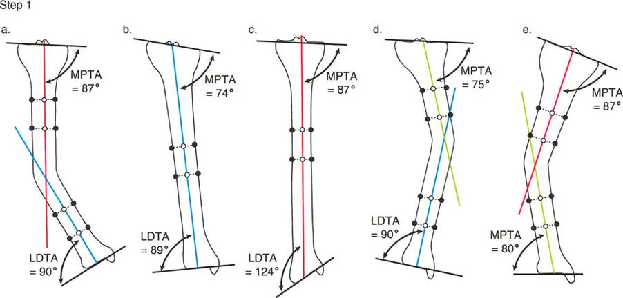
The Malorientation Test is the diagnostic process used to pinpoint the exact bone and segment responsible for the Mechanical Axis Deviation. Once you have confirmed that the limb is malaligned you must measure the joint orientation angles to find the culprit.
Begin by drawing the mechanical axis of the femur connecting the center of the femoral head to the center of the knee. Then draw the mechanical axis of the tibia connecting the center of the knee to the center of the ankle.
Next measure the mLDFA and the MPTA. Compare your findings against the normative data.
If the mLDFA is 87 degrees normal but the MPTA is 75 degrees abnormal varus you have definitively isolated the deformity to the tibia. The femur is mechanically sound.
If both the mLDFA and the MPTA fall outside of normal ranges you are dealing with a combined femoral and tibial deformity requiring a double level correction.
The Malorientation Test prevents the catastrophic error of performing a compensatory osteotomy. For example if a patient has a varus femur creating a valgus tibia to correct the overall Mechanical Axis Deviation will result in a perfectly straight leg with a highly oblique joint line. This oblique joint line creates pathological shear forces across the knee leading to rapid joint destruction. You must correct the bone that is actually deformed.
Identifying the Center of Rotation of Angulation
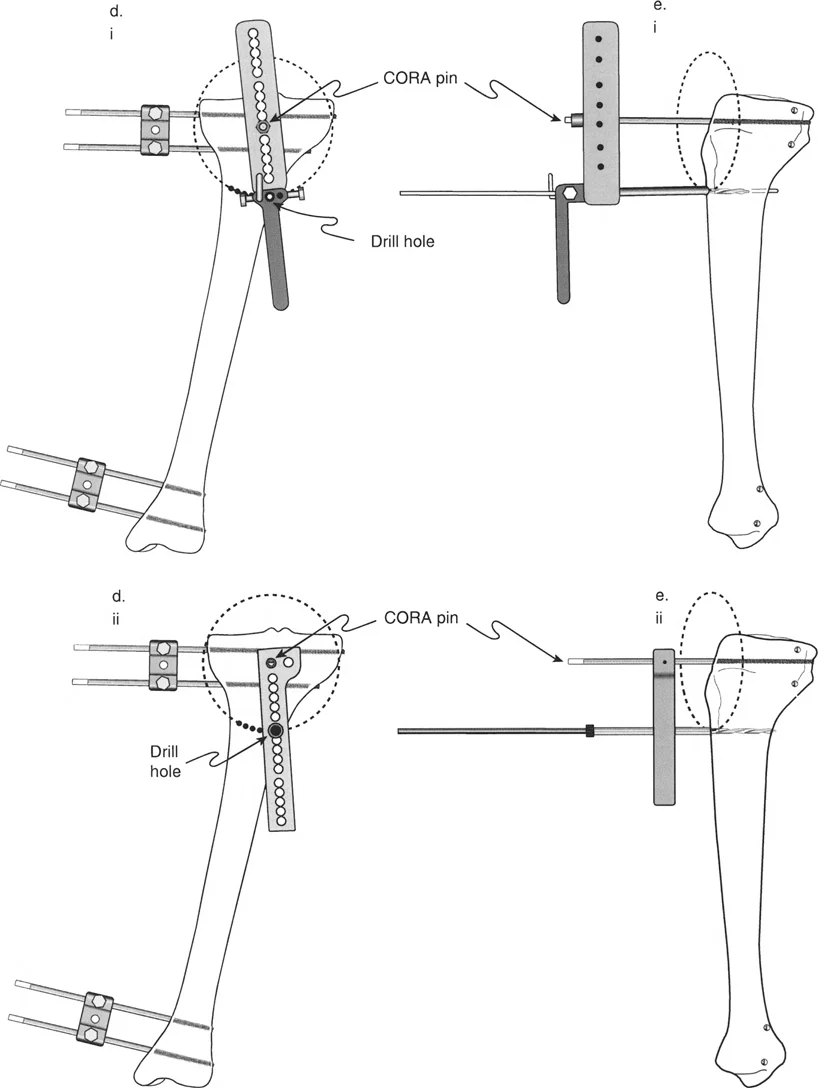
Once you have isolated the deformity to the tibia using the Malorientation Test the next step is to locate the exact apex of the deformity. In the Paley method this apex is known as the Center of Rotation of Angulation. Finding the true Center of Rotation of Angulation is the most critical step in preoperative planning because it dictates where you will cut the bone and how you will manipulate the fragments.
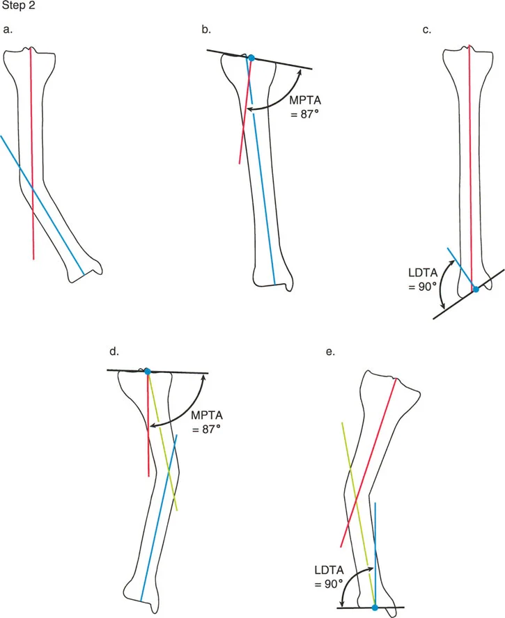
To find the Center of Rotation of Angulation in the tibia using mechanical axis planning follow these precise steps.
First draw the proximal mechanical axis line. Draw a line starting from the center of the knee joint extending distally. This line must intersect the proximal tibial joint line at exactly 87 degrees which is the normal MPTA.
Second draw the distal mechanical axis line. Draw a line starting from the center of the ankle joint extending proximally. This line must intersect the distal tibial joint line at exactly 90 degrees which is the normal LDTA.
Third locate the intersection. Extend both the proximal and distal mechanical axis lines until they intersect within the diaphysis or metaphysis of the tibia.
The exact point where these two lines cross is the Center of Rotation of Angulation. The angle formed between these two intersecting lines is the true magnitude of the deformity.
Because the mechanical and anatomic axes of the tibia are nearly parallel you can also find the Center of Rotation of Angulation using anatomic axis planning. Draw a line down the center of the medullary canal of the proximal segment and a line up the center of the medullary canal of the distal segment. The intersection of these two mid diaphyseal lines will yield the same Center of Rotation of Angulation and the same magnitude of angular deformity.
Mastering the Three Paley Osteotomy Rules
Locating the Center of Rotation of Angulation is only half the battle. The surgeon must now decide where to perform the osteotomy the actual bone cut and where to place the mechanical hinge for correction. Dr Dror Paley established three fundamental geometric rules that govern how bone fragments behave when angulated and translated.
Mastering these three rules allows the surgeon to predict exactly how the mechanical axis will align after the correction is executed.
Paley Osteotomy Rule One
Rule One states that when the osteotomy bone cut and the hinge axis of correction are both placed exactly at the Center of Rotation of Angulation the bone will undergo pure angular correction without any translation.
This is the most mechanically elegant and stable type of correction. By cutting the bone at the apex of the deformity and hinging the fragments at that exact same point the proximal and distal mechanical axes will perfectly align. The bone ends will remain in direct contact maximizing the surface area for bone healing. In clinical practice this is often achieved with a closing wedge or opening wedge osteotomy performed directly at the deformity apex.
Paley Osteotomy Rule Two
Rule Two states that when the hinge axis of correction is placed at the Center of Rotation of Angulation but the osteotomy bone cut is performed at a different level away from the Center of Rotation of Angulation the bone will undergo both angular correction and translation.
This rule is highly applicable in clinical scenarios where the Center of Rotation of Angulation is located very close to a joint line. For example in a severe proximal tibial deformity the Center of Rotation of Angulation might be situated within the articular block making an osteotomy at that exact level impossible without destroying the joint.
By applying Rule Two the surgeon can perform the osteotomy further down the tibial shaft in healthy diaphyseal bone. Because the hinge point remains at the true Center of Rotation of Angulation the mechanical axis will still be perfectly restored. However the bone ends at the osteotomy site will translate shifting medially or laterally relative to each other. The surgeon must anticipate this translation and ensure that adequate bone contact remains for healing and that the soft tissue envelope can accommodate the translated bone segment.
Paley Osteotomy Rule Three
Rule Three states that when both the osteotomy bone cut and the hinge axis of correction are placed away from the Center of Rotation of Angulation the correction will result in a new secondary deformity typically a translation deformity that misaligns the mechanical axis.
Rule Three is essentially the definition of a planning error. If a surgeon ignores the Center of Rotation of Angulation entirely cuts the bone wherever it is convenient and hinges the bone at the osteotomy site the mechanical axis of the proximal and distal segments will become parallel but they will not be collinear. This creates a zig zag deformity. The limb may look straight to the naked eye but the mechanical weight bearing line will be shifted resulting in abnormal joint loading.
There are rare advanced applications where Rule Three is used intentionally to correct a pre existing translational deformity but for the vast majority of standard angular corrections Rule Three must be strictly avoided.
Strategies for Multiapical Tibial Deformities
While a single Center of Rotation of Angulation is common in simple post traumatic malunions many developmental metabolic or severe traumatic conditions result in bowed bones with multiple apices of deformity. These are known as multiapical deformities.
Attempting to correct a multiapical bowed tibia with a single osteotomy will result in massive translation and a failure to restore the mechanical axis. The Paley method addresses this by breaking the bone down into three or more distinct segments.
For a double level deformity the surgeon must draw three lines.
First the proximal mechanical axis line based on the normal MPTA.
Second the distal mechanical axis line based on the normal LDTA.
Third a mid diaphyseal anatomic axis line representing the middle segment of the bowed bone.
The intersection of the proximal line and the middle line creates the proximal Center of Rotation of Angulation. The intersection of the distal line and the middle line creates the distal Center of Rotation of Angulation.
This precise geometric mapping dictates that a double level osteotomy is required. By applying Paley Osteotomy Rule One or Rule Two at each distinct Center of Rotation of Angulation the surgeon can systematically unfurl the bowed bone restoring a perfectly straight mechanical axis from the knee to the ankle.
Clinical Applications in Joint Preservation and Trauma
The mathematical principles of mechanical axis planning are not abstract academic concepts. They are daily tools used in the operating room to save joints and restore function.
In the realm of joint preservation the High Tibial Osteotomy relies entirely on these principles. A patient with medial compartment osteoarthritis and a varus tibial deformity requires a precise shift of the mechanical axis. By calculating the exact Center of Rotation of Angulation and planning a medial opening wedge osteotomy the surgeon can intentionally shift the Mechanical Axis Deviation laterally unloading the damaged medial cartilage and transferring the weight bearing forces to the healthy lateral compartment.
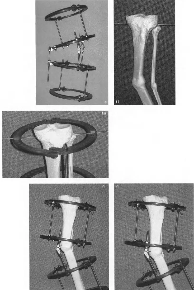
In complex trauma and limb lengthening the application of hexapod circular fixators like the Taylor Spatial Frame requires absolute fluency in Paley principles. The software that drives a hexapod frame requires the surgeon to input the exact location of the deformity apex the magnitude of the angulation and the precise mounting parameters of the rings. If the surgeon inputs an incorrect Center of Rotation of Angulation the frame will execute a flawed correction leading to iatrogenic translation and mechanical axis deviation.
High Yield Surgical Pearls for Tibial Planning
To synthesize this masterclass into actionable clinical knowledge review these critical surgical pearls before executing your next deformity correction plan.
- Always Control for Rotation. A radiograph with the patella pointing sideways renders all frontal plane measurements useless. Ensure the patella is strictly forward during the standing radiograph.
- Respect the Joint Line Convergence Angle. Never assume a severe Mechanical Axis Deviation is entirely bony. Evaluate the JLCA to rule out ligamentous laxity or severe asymmetric cartilage loss.
- Utilize the Tibial Anatomic Advantage. Because the mechanical and anatomic axes of the tibia are nearly parallel you can confidently use mid diaphyseal lines to find the Center of Rotation of Angulation in complex diaphyseal deformities.
- Beware of Compensatory Osteotomies. Always perform the Malorientation Test to find the true source of the deformity. Correcting a varus femur by creating a valgus tibia will destroy the knee joint through shear forces.
- Anticipate Translation with Rule Two. If you must cut the bone away from the Center of Rotation of Angulation you must plan for the resulting translation. Ensure you have adequate soft tissue coverage and sufficient bony apposition for union.
- Verify the Hinge Placement. In an opening wedge high tibial osteotomy the lateral cortical hinge is your axis of correction. If this hinge breaks or is placed incorrectly you lose control of the correction and risk unwanted translation or multiplanar deformity.
Mastering tibial mechanical axis planning elevates the orthopedic surgeon from a mere carpenter to a true structural engineer of the human body. By rigorously applying the Malalignment Test identifying the Center of Rotation of Angulation and respecting the Paley Osteotomy Rules you ensure that every correction you perform is biologically sound mechanically perfect and built to last a lifetime.
!!! info "Academic Resource & Medical Review"
This academic resource was prepared and medically reviewed by Prof. Dr. Mohammed Hutaif, Consultant Orthopedic & Spine Surgeon. It is formulated specifically for medical students, orthopedic residents, and surgeons preparing for high-stakes board examinations (AAOS, FRCS Tr & Orth, Arab Board).
!!! warning "Disclaimer"
The surgical techniques, classifications, and clinical guidelines presented herein are for educational and academic review purposes only. They are not intended to replace institutional protocols or independent clinical judgment.
You Might Also Like