Mastering Six-Axis Deformity Correction: Paley Principles for Orthopedic Surgeons
Key Takeaway
Six-Axis Deformity Analysis, pioneered by Dr. Dror Paley, evaluates and corrects bone malalignment across six degrees of freedom. It uses Mechanical Axis Deviation (MAD), Center of Rotation of Angulation (CORA), and Paley's osteotomy rules for precise, multiplanar orthopedic correction with hexapod fixators.
Introduction to Modern Deformity Correction
The evolution of orthopedic deformity correction has transitioned from the foundational circular tensioned wire principles of Gavriil Ilizarov to the highly sophisticated computer assisted methodologies pioneered by Dr Dror Paley and Dr J Charles Taylor. At the heart of this evolution is Six Axis Deformity Analysis, a comprehensive framework that evaluates and corrects bone malalignment across all six degrees of freedom in three dimensional space.
For the orthopedic surgeon in training, mastering six axis deformity analysis is not merely about learning how to apply a Taylor Spatial Frame or a modern hexapod fixator. It is about fundamentally rewiring how you perceive spatial geometry, mechanical axes, and bone biology. This masterclass will exhaustively bridge the gap between dry textbook theory and high yield clinical application, anchoring every concept in Paley principles of deformity correction. To achieve total mastery, one must move beyond two dimensional radiographic analysis and embrace the complex multi planar reality of osteology and biomechanics. The ultimate goal is to restore normal mechanical axis alignment, ensuring optimal load distribution across the articular cartilage and preventing early onset osteoarthritis.
Foundational Paley Principles of Deformity Correction
Before deconstructing the six degrees of freedom, it is impossible to discuss deformity correction without a rigid understanding of the foundational principles established by Dr Dror Paley. The entire six axis system relies on accurately identifying the mechanical axis, the anatomical axis, and the apex of the deformity. Mastery of these concepts is non negotiable for any surgeon attempting to utilize hexapod technology.
Calculating Mechanical Axis Deviation MAD
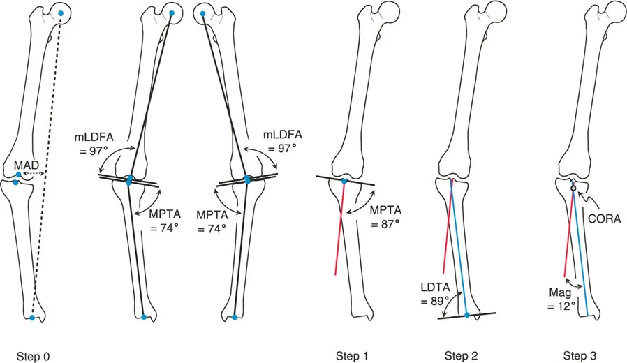
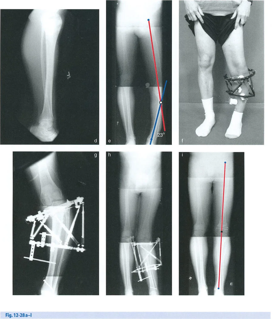
The mechanical axis of the lower extremity is a straight line drawn from the center of the femoral head to the center of the ankle joint at the tibial plafond. In a normal limb, this line bisects the knee joint just medial to the tibial spines. Mechanical Axis Deviation or MAD occurs when this line falls outside the normal parameters, shifting either medially to create a varus deformity or laterally to create a valgus deformity.
Quantifying the MAD is the absolute first step in determining the magnitude of the biomechanical overload on the joint compartments. To perform the Malalignment Test, the surgeon must obtain a standing full length anteroposterior radiograph of the bilateral lower extremities with the patellae oriented forward. A line is drawn from the center of the femoral head to the center of the ankle joint. The distance from the center of the knee joint to this mechanical axis line is measured in millimeters. A normal MAD is typically 1 to 8 millimeters medial to the center of the knee. Any deviation beyond this narrow window dictates the need for further segmental analysis to isolate the source of the deformity.
Defining the Center of Rotation of Angulation CORA
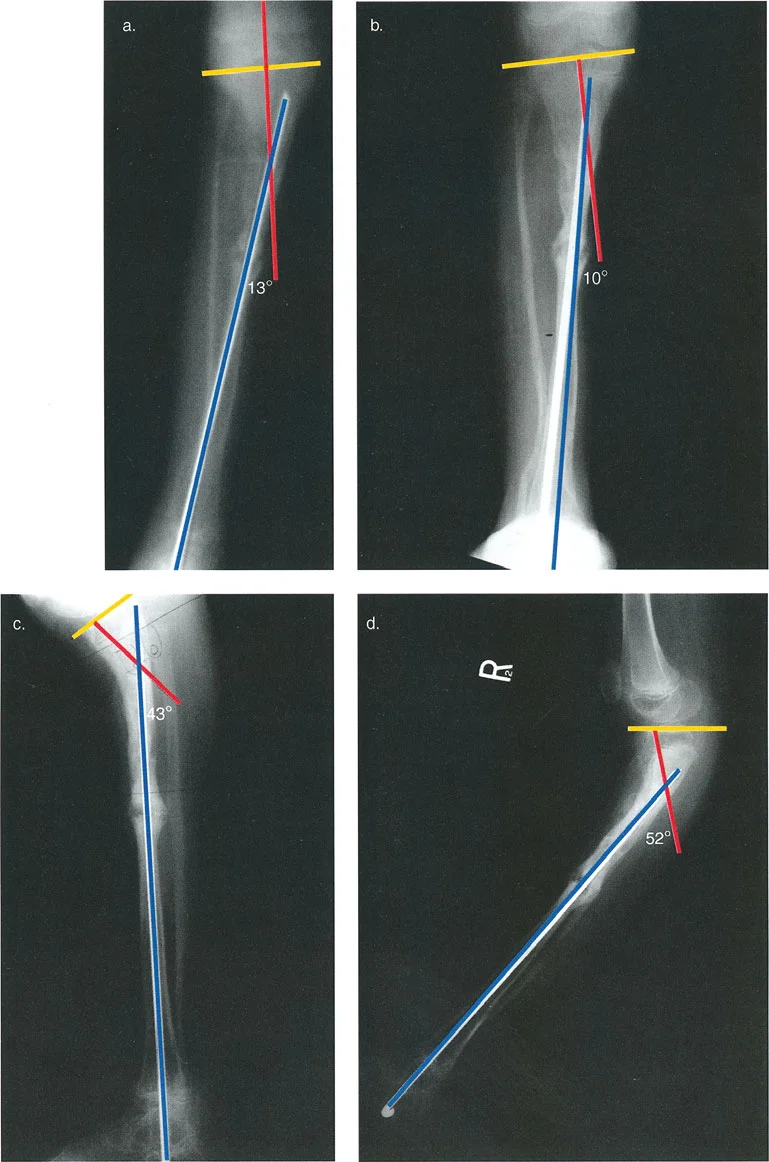
The Center of Rotation of Angulation, universally known as CORA, is the intersection point of the proximal and distal mechanical or anatomical axes of a deformed bone segment. Identifying the CORA is the crux of Paley deformity planning.
To find the CORA, the surgeon must draw the mid diaphyseal lines for both the proximal and distal segments of the deformed bone on orthogonal radiographs. The point where these two lines intersect is the CORA. In simple uniapical deformities, there is a single CORA. However, in multiapical deformities, drawing the axes of the proximal, middle, and distal segments will reveal multiple CORAs. Understanding the location of the CORA dictates where the osteotomy should be performed and where the hinge of the external fixator must be placed to achieve pure angular correction.
Standard Joint Orientation Angles
Deformity analysis relies heavily on standard joint orientation angles to determine whether a deformity is femoral, tibial, or intra articular. When inputting data into a six axis CAD software, recognizing which of these angles is abnormal dictates the reference segment and the exact parameters of the required correction.
The Malorientation Test involves measuring the mechanical and anatomical joint orientation angles and comparing them to established normal population values.
| Joint Orientation Angle | Full Name | Normal Value Range | Clinical Significance |
|---|---|---|---|
| mLDFA | Mechanical Lateral Distal Femoral Angle | 85° - 90° (Nominal 87°) | Evaluates distal femoral varus or valgus. |
| MPTA | Medial Proximal Tibial Angle | 85° - 90° (Nominal 87°) | Evaluates proximal tibial varus or valgus. |
| LDTA | Lateral Distal Tibial Angle | 88° - 90° (Nominal 89°) | Evaluates distal tibial varus or valgus. |
| JLCA | Joint Line Convergence Angle | 0° - 2° | Evaluates intra articular ligamentous laxity or cartilage loss. |
| mLPFA | Mechanical Lateral Proximal Femoral Angle | 85° - 95° (Nominal 90°) | Evaluates proximal femoral varus or valgus. |
If the MAD is abnormal, the surgeon systematically checks the mLDFA, MPTA, and JLCA. If the mLDFA is abnormal, the deformity lies within the femur. If the MPTA is abnormal, the deformity is in the tibia. If the JLCA is widened, there is an intra articular component such as collateral ligament laxity or asymmetrical cartilage wear that must be accounted for during surgical planning.
Paley Osteotomy Rules for Deformity Correction
Dr Paley formulated three fundamental osteotomy rules based on the relationship between the CORA, the osteotomy site, and the hinge of the corrective device. Adhering to these rules prevents the creation of secondary iatrogenic deformities during the correction process.
Rule One Osteotomy and Hinge at CORA
When the osteotomy and the hinge of the corrective frame are both placed exactly at the CORA, the bone segments will undergo pure angular correction. The anatomical axes of the proximal and distal segments will realign perfectly without any secondary translation. This is the ideal scenario for deformity correction, often utilized in simple closing wedge, opening wedge, or dome osteotomies.
Rule Two Osteotomy Off CORA with Hinge at CORA
In many clinical scenarios, performing an osteotomy exactly at the CORA is biologically or mechanically unfavorable. For example, the CORA may be located within the joint space or in an area of poor soft tissue coverage. Under Rule Two, the osteotomy is performed at a different level away from the CORA, but the hinge of the external fixator remains perfectly aligned with the CORA.
When correction occurs, the bone ends at the osteotomy site will undergo both angulation and translation. However, because the hinge is at the CORA, the mechanical axes of the proximal and distal segments will ultimately realign perfectly at the end of the correction. The surgeon must ensure there is adequate space for this translation to occur without tethering neurovascular structures.
Rule Three Osteotomy and Hinge Off CORA
If both the osteotomy and the hinge are placed away from the CORA, the resulting correction will induce a secondary translation anomaly, often referred to as a dog leg deformity. The mechanical axes of the proximal and distal segments will end up parallel but translated. This rule is generally avoided unless the surgeon is intentionally trying to create a translational offset to compensate for a parallel axis deformity elsewhere in the limb.
Mastering the Six Degrees of Freedom
To correct a deformity using hexapod technology, one must first accurately define it. A bone segment in three dimensional space can be deformed relative to its corresponding normal segment in six distinct ways, known as the six degrees of freedom. These are categorized into translations and rotations along the three anatomical axes of coronal, sagittal, and axial.
Coronal and Sagittal Plane Angulations
Angulation is the most visually apparent component of a deformity.
* Coronal Plane Angulation manifests as varus with a medial apex or valgus with a lateral apex.
* Sagittal Plane Angulation manifests as procurvatum with an anterior apex or recurvatum with a posterior apex.
When inputting these parameters into the software, the surgeon must define the magnitude of the angle in degrees and the exact location of the apex.
Coronal and Sagittal Plane Translations
Translation occurs when the distal segment is shifted linearly relative to the proximal segment without a change in angulation.
* Coronal Plane Translation is measured as medial or lateral displacement of the distal segment in millimeters.
* Sagittal Plane Translation is measured as anterior or posterior displacement of the distal segment in millimeters.
Axial Plane Translation and Rotation
The axial plane involves the length and twist of the bone along its mechanical axis.
* Axial Translation refers to shortening or lengthening along the mechanical axis. Limb length discrepancy is quantified in millimeters.
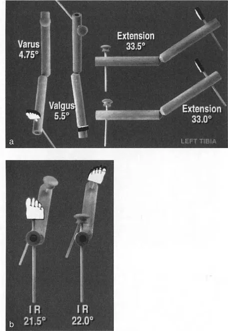
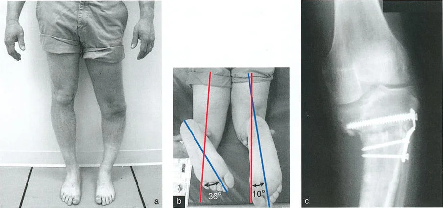
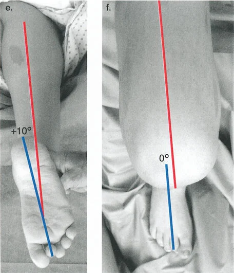
* Axial Rotation refers to internal or external torsion around the mechanical axis, measured in degrees. This is often assessed clinically using rotational profiles or radiographically using CT scan torsion studies.
When these six deformities exist simultaneously, they create complex multi planar malalignments that cannot be accurately corrected with simple hinges, uniplanar external fixators, or single plane closing wedge osteotomies. This is the precise indication for a six axis hexapod frame.
Analyzing the Oblique Plane Deformity
Often, what appears as a combined coronal and sagittal plane angulation on standard anteroposterior and lateral radiographs is actually a single angular deformity occurring in an oblique plane. Paley principles dictate that true deformity correction must occur in this oblique plane to be mechanically efficient and biologically sound.
Trigonometry of Single Angular Deformities
The oblique plane angulation is calculated by forming a geometric right triangle based on the apparent deformities on orthogonal radiographs.
* The height of the triangle equals the magnitude of the deformity on the lateral radiograph.
* The base of the triangle equals the magnitude of the deformity on the anteroposterior radiograph.
* The triangle is completed by drawing a hypotenuse. The true magnitude of the oblique plane angular deformity is the length of this hypotenuse, calculated using the Pythagorean theorem.
Furthermore, the orientation of this oblique plane relative to the coronal plane can be determined using trigonometric tangent functions. Understanding this mathematical reality allows the surgeon to place the hinges of a traditional Ilizarov frame precisely perpendicular to the oblique plane of deformity. However, with the advent of the Taylor Spatial Frame and modern hexapods, the software algorithm handles this complex trigonometry seamlessly, provided the surgeon inputs the correct mounting parameters and accurately defines the six degrees of freedom.
Taylor Spatial Frame and Hexapod Technology
The introduction of the Taylor Spatial Frame revolutionized the application of Paley principles. It took the biological advantages of the Ilizarov method circular wire fixation, minimal soft tissue disruption, and distraction osteogenesis and combined them with the mathematical precision of computer assisted robotics.
Stewart Gough Platform Mechanics
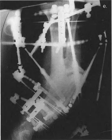
The Taylor Spatial Frame is based on the Stewart Gough platform, a hexapod robotic mechanism originally utilized in flight simulators and industrial robotics. The system utilizes two rings connected by six telescopic struts with universal joints at each end. By adjusting the lengths of these six struts independently, the rings can be manipulated to achieve simultaneous correction of all six degrees of freedom.
Unlike traditional Ilizarov frames that require complex hinge building and frequent frame modifications in the clinic, the hexapod frame remains statically mounted. The virtual hinge is created by the software, allowing the center of rotation to be placed anywhere in three dimensional space, perfectly satisfying Paley Osteotomy Rules without the physical constraints of mechanical hinges.
Computer Assisted Design CAD Software Inputs
A CAD program, originally developed by Orthocrat Ltd and subsequently refined by various orthopedic manufacturers, allows for detailed and accurate deformity and mounting parameter analysis using digital radiographic images. This software requires the surgeon to input three distinct sets of data to generate a daily strut adjustment prescription for the patient.
- Deformity Parameters This includes the exact quantification of the six degrees of freedom angulation, translation, rotation, and length discrepancy.
- Frame Parameters This defines the physical hardware used, including the diameter of the proximal and distal rings, and the initial lengths of the six struts.
- Mounting Parameters This is the most critical and frequently mishandled step. It defines exactly where the reference ring is located in three dimensional space relative to the reference bone segment.
Step by Step Preoperative Planning Protocol
Total mastery of deformity correction requires a meticulous, systematic approach to preoperative planning. The phrase measure twice, cut once is heavily amplified in hexapod surgery. An error in planning will result in the software generating a prescription that perfectly executes the wrong correction.
Step One Radiographic Evaluation
High quality, calibrated orthogonal radiographs are the foundation of accurate planning.
1. Obtain a standing 51 inch AP radiograph of the bilateral lower extremities to assess MAD.
2. Obtain dedicated AP and lateral radiographs of the deformed bone segment. These must be perfectly orthogonal, meaning the x ray beam is exactly 90 degrees between the two views.
3. Place a radiographic scaling marker typically a 25 millimeter spherical marker at the level of the bone to allow the digital templating software to calibrate magnification.
Step Two Identifying the Reference Segment and Origin
The surgeon must choose whether the proximal or distal bone segment will serve as the reference segment. The reference segment is assumed to be stationary in the software, while the moving segment is manipulated to align with it.
1. Identify the anatomical axis of the reference segment.
2. Define the Origin. The Origin is a specific point on the reference segment, usually the center of the joint line or the tip of a prominent anatomical landmark. All deformity and mounting parameters will be measured relative to this exact point.
Step Three Software Parameter Input
With the radiographs calibrated and the origin defined, the surgeon inputs the data into the web based CAD software.
1. Input the AP and Lateral angulation and translation of the moving segment relative to the reference segment.
2. Input the axial rotation based on clinical examination or CT scan data.
3. Input the desired length change.
4. Input the AP, Lateral, and Axial mounting parameters. This tells the software exactly how far anterior, lateral, and distal the center of the reference ring is from the anatomical Origin point.
Surgical Execution and Frame Application
The transition from digital planning to the operating room requires precise surgical technique. The biological viability of the bone and soft tissues must be preserved to ensure successful distraction osteogenesis.
Mounting Parameters and Reference Rings
During surgery, the application of the reference ring is the most critical step. The ring must be applied exactly as it was planned in the software, or the surgeon must meticulously record the actual intraoperative mounting parameters to update the software postoperatively.
- Surgical Pearls for Ring Application
- Mount the reference ring orthogonal to the anatomical axis of the reference bone segment. This simplifies the mounting parameters and reduces the risk of software input errors.
- Use a master tab or a specific strut attachment point aligned perfectly with the anterior anatomical axis of the bone to serve as the rotational reference.
- Ensure adequate soft tissue clearance. A minimum of two fingerbreadths of clearance between the ring and the skin is required to accommodate postoperative swelling and prevent pressure necrosis.
The Corticotomy and Distraction Osteogenesis
Following frame application, the bone is divided. Paley advocates for a low energy, percutaneous corticotomy rather than a high energy oscillating saw osteotomy. Using a drill and an osteotome preserves the endosteal blood supply and the periosteal sleeve, which are vital for the generation of new bone regenerate.
- Key Takeaways for Biological Preservation
- Perform the corticotomy as the final step of the procedure to prevent displacement of the bone segments during wire and half pin insertion.
- Observe a latency period of 5 to 7 days before initiating strut adjustments. This allows the acute inflammatory phase of fracture healing to subside and mesenchymal stem cells to populate the corticotomy gap.
- The optimal rate of distraction is 1 millimeter per day, divided into four equal adjustments of 0.25 millimeters. This rhythm mimics the natural growth plate and optimizes osteogenesis.
Postoperative Adjustment Phase
The patient is provided with a printed prescription generated by the CAD software. This prescription details exactly which struts to turn, in which direction, and by how much, for every day of the correction phase.
The surgeon must monitor the patient closely with serial radiographs typically every 7 to 14 days during the distraction phase. If the bone regenerate is forming too poorly, the rate of distraction may need to be slowed. If the bone is consolidating too rapidly leading to premature consolidation, the rate must be increased.
Furthermore, the surgeon must continually assess the soft tissues. As the bone is corrected, muscles, nerves, and blood vessels are placed under tension. Active physical therapy is mandatory to prevent joint contractures. If the patient develops severe pain or neurological deficits, the correction must be halted immediately, and the struts may even need to be reversed to relieve tension on the compromised nerve.
Total mastery of six axis deformity correction is a lifelong pursuit. By rigorously applying Paley principles of CORA, MAD, and joint orientation angles, and by leveraging the mathematical precision of hexapod CAD software, the orthopedic surgeon can achieve unparalleled accuracy in restoring mechanical alignment and improving patient outcomes.
!!! info "Academic Resource & Medical Review"
This academic resource was prepared and medically reviewed by Prof. Dr. Mohammed Hutaif, Consultant Orthopedic & Spine Surgeon. It is formulated specifically for medical students, orthopedic residents, and surgeons preparing for high-stakes board examinations (AAOS, FRCS Tr & Orth, Arab Board).
!!! warning "Disclaimer"
The surgical techniques, classifications, and clinical guidelines presented herein are for educational and academic review purposes only. They are not intended to replace institutional protocols or independent clinical judgment.
You Might Also Like