Mastering Paley Orthopedic Deformity Correction: Geometric Principles for Surgeons
Key Takeaway
Paley orthopedic deformity correction utilizes precise geometric principles, including COG, ACA, and Mechanical Axis Deviation, to restore limb alignment. It often involves distraction osteogenesis, guided by Ilizarov's tension-stress effect, to manipulate bone segments and prevent complications like malunion, ensuring optimal joint orientation.
Mastering Paley Orthopedic Deformity Correction The Ultimate Surgeons Guide
In the realm of complex orthopedic deformity correction, precision is not merely a clinical goal; it is a biological and mechanical absolute. The historical days of estimating angular deformities and relying solely on intraoperative fluoroscopy for acute corrections have been entirely superseded by mathematical certainty. Based on the foundational geometric principles established by Dr. Dror Paley and the biological legacy of Gavriil Ilizarovs tension-stress effect, understanding the intricate interplay between hardware constructs and osteotomy geometry is what separates a successful distraction osteogenesis from catastrophic malunion, premature consolidation, or regenerate failure.
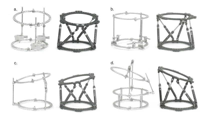
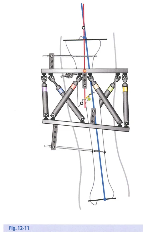
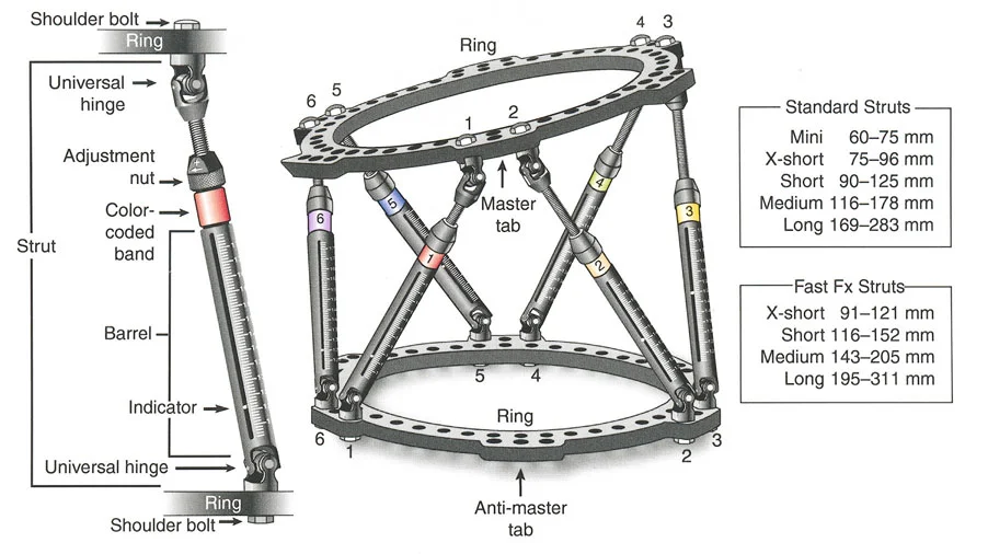
This comprehensive guide deconstructs the critical considerations for hardware application, hinge placement, distraction mechanics, and the strategic sequencing of gradual corrections. Whether you are utilizing classic circular Ilizarov frames, modern hexapod systems such as the Taylor Spatial Frame, or monolateral fixators, the geometric rules governing the Center of Rotation of Angulation, the Axis of Correction of Angulation, and Mechanical Axis Deviation remain absolute and unforgiving.
By mastering these principles, orthopedic surgeons can reliably manipulate bone segments in three-dimensional space, ensuring optimal joint orientation while respecting the delicate biology of the newly forming regenerate bone.
Foundational Geometric Principles of Deformity Correction
Before manipulating bone, the surgeon must be able to quantify the deformity using standardized, reproducible metrics. Dr. Dror Paley revolutionized orthopedic surgery by standardizing the nomenclature and geometric analysis of the lower extremity. A successful correction relies entirely on restoring the normal mechanical axis and the orientation of the joints relative to that axis.
Understanding Mechanical Axis Deviation
The Mechanical Axis Deviation is the primary indicator of lower extremity malalignment. In a normal lower limb, the mechanical axis line drawn from the center of the femoral head to the center of the ankle joint should pass precisely through or slightly medial to the center of the knee joint. When this line falls outside the normal parameters, a Mechanical Axis Deviation is present, indicating either a varus deformity (axis falls medial to the knee center) or a valgus deformity (axis falls lateral to the knee center).
Correcting the Mechanical Axis Deviation is the ultimate goal of deformity surgery. Failure to restore this axis leads to eccentric loading of the knee joint cartilage, inevitably resulting in early-onset osteoarthritis and mechanical failure of the limb.
Joint Orientation Angles
To correct a deformity, one must understand the normal angular relationships between the mechanical axes of the bones and their respective joint lines. These are referred to as Joint Orientation Angles. The most critical angles in the lower extremity include the mechanical Lateral Distal Femoral Angle and the Medial Proximal Tibial Angle.
Below is a reference table for standard normal values of lower extremity joint orientation angles, which must be memorized for preoperative templating.
| Angle Acronym | Full Anatomical Name | Normal Value Range | Clinical Significance |
|---|---|---|---|
| mLDFA | Mechanical Lateral Distal Femoral Angle | 85 to 90 degrees (Avg 87) | Dictates distal femoral varus or valgus. |
| MPTA | Medial Proximal Tibial Angle | 85 to 90 degrees (Avg 87) | Dictates proximal tibial varus or valgus. |
| JLCA | Joint Line Convergence Angle | 0 to 2 degrees | Indicates intra-articular ligamentous laxity or cartilage loss. |
| LPFA | Lateral Proximal Femoral Angle | 85 to 95 degrees (Avg 90) | Evaluates the proximal femur and femoral neck orientation. |
| LDTA | Lateral Distal Tibial Angle | 86 to 92 degrees (Avg 89) | Dictates ankle joint orientation in the coronal plane. |
Surgical Pearls for Joint Orientation
- Bilateral Templating: Always obtain full-length, weight-bearing standing radiographs of both legs. Use the contralateral normal leg as your patient-specific template whenever possible.
- JLCA Consideration: A high Joint Line Convergence Angle often masks or exacerbates the true osseous deformity. You must differentiate between bone deformity and ligamentous laxity before planning your osteotomy.
- Sagittal Plane: Do not forget the sagittal plane. The Posterior Distal Femoral Angle and Posterior Proximal Tibial Angle are equally critical to prevent iatrogenic recurvatum or procurvatum.
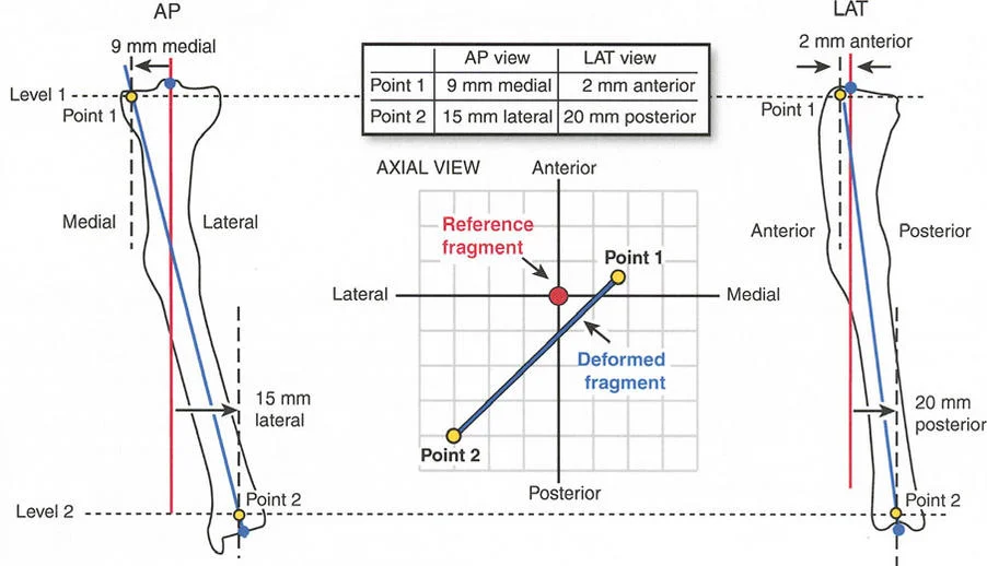
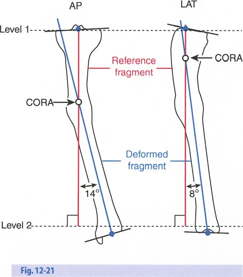
Identifying the Center of Rotation of Angulation
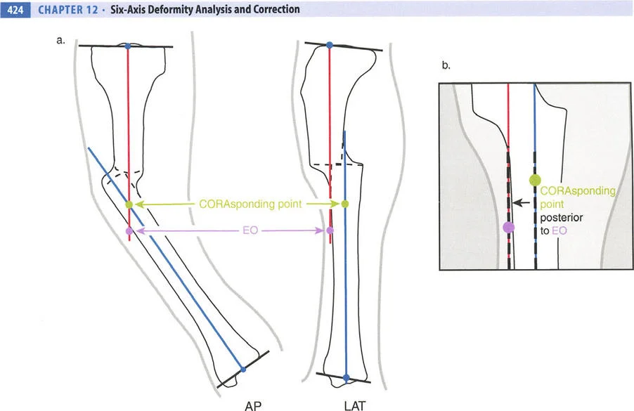
The Center of Rotation of Angulation is the foundational geometric concept in Paleys method. It represents the precise point in space where the proximal mechanical axis line and the distal mechanical axis line intersect. Finding the Center of Rotation of Angulation is the first and most vital step in preoperative planning.
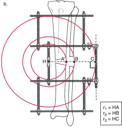
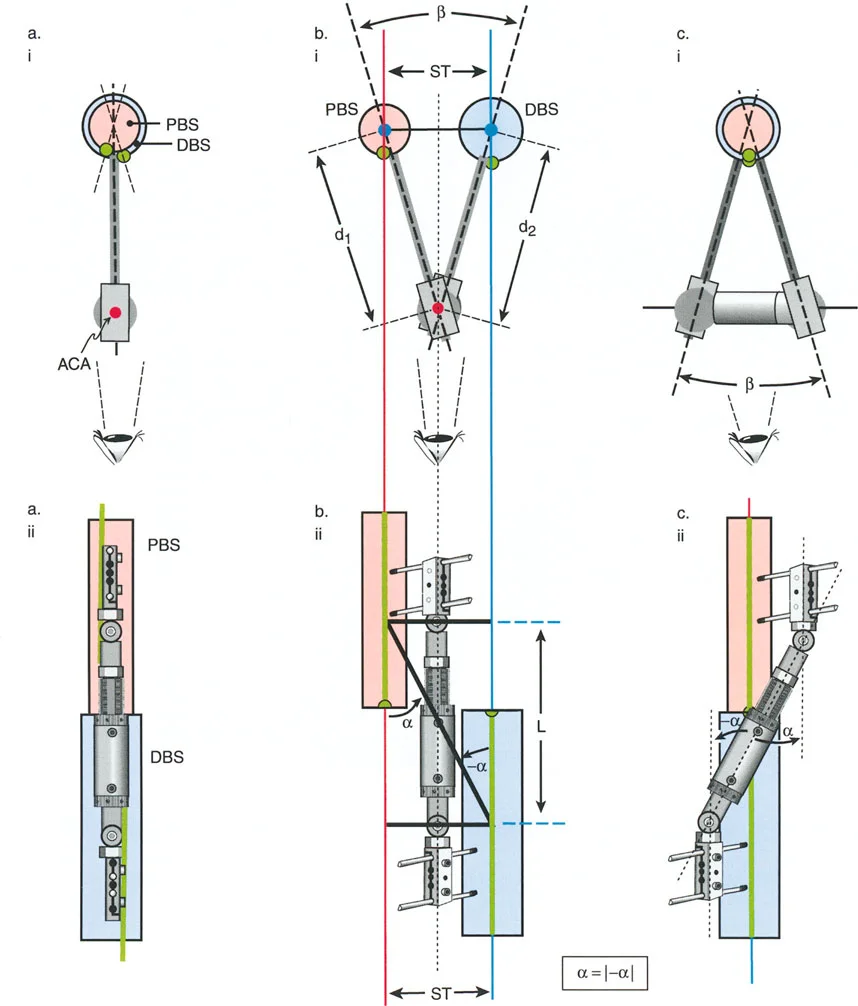
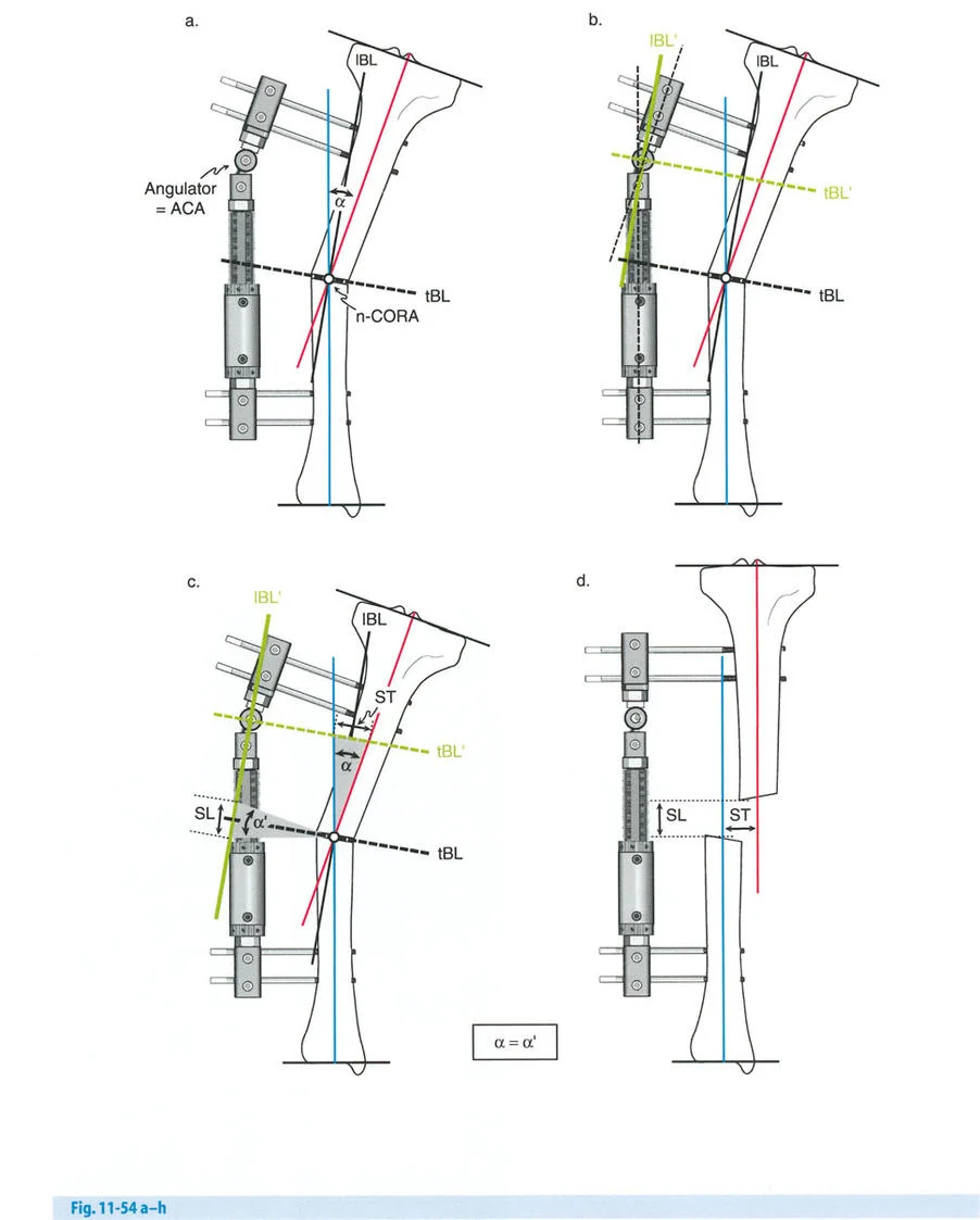
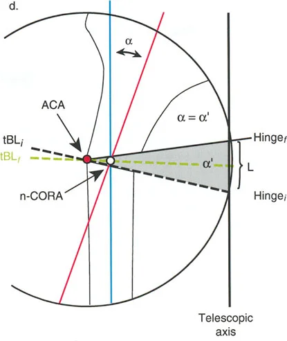
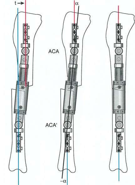
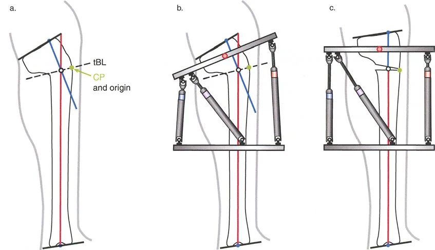
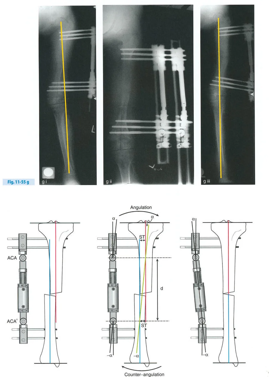
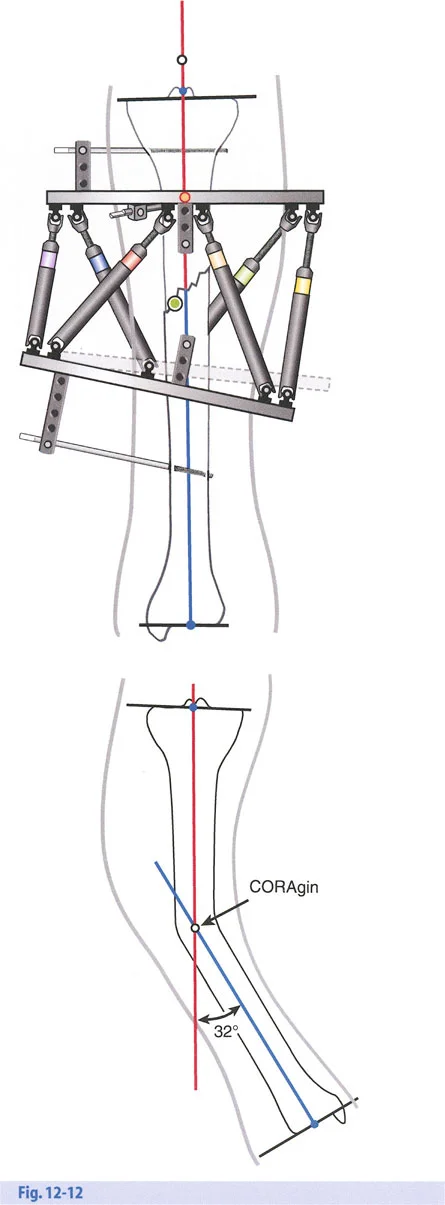
The Axis of Correction of Angulation
While the Center of Rotation of Angulation is a fixed anatomical point based on the patients deformity, the Axis of Correction of Angulation is a mechanical point chosen by the surgeon. The Axis of Correction of Angulation represents the physical hinge on your external fixator or the focal point of your internal fixation correction.
For a perfect correction without unintended translation, the Axis of Correction of Angulation must align perfectly with the Center of Rotation of Angulation. When these two points diverge, the geometry of the bone ends will shift unpredictably, leading to the complications described in Paleys Osteotomy Rules.
The Biological Imperative of Distraction Osteogenesis
Before diving deeper into hardware mechanics and osteotomy rules, the surgeon must understand the biological substrate being manipulated. Gavriil Ilizarov discovered that living tissue, when subjected to slow, steady tension, becomes metabolically activated. This tension-stress effect stimulates osteogenesis, angiogenesis, and histogenesis, allowing for the lengthening of bone, muscle, nerve, and skin.
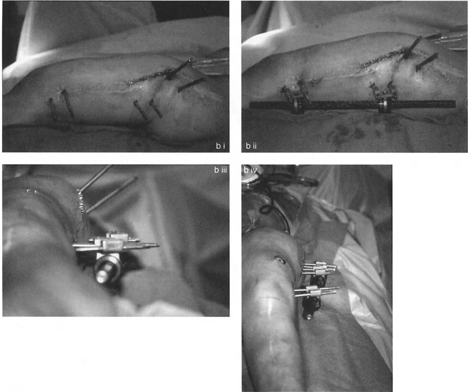
Stability Versus Rigidity in Frame Construction
This biological miracle is highly dependent on mechanical stability. The regenerate bone acts as a mechanotransducer. If a frame construct is entirely rigid, the bone will experience stress shielding and fail to consolidate, leading to delayed union. Conversely, if the construct is too loose, shear forces will destroy the delicate capillary buds forming in the distraction gap. This vascular destruction leads to fibrocartilage formation and ultimately non-union.
The hardware must be designed to provide controlled axial micromotion while strictly preventing shear and rotational instability. This is achieved through the proper tensioning of wires, the strategic spread of half-pins, and the appropriate sizing of the circular rings relative to the soft tissue envelope.
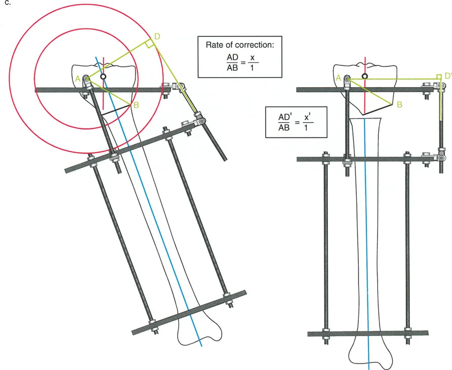
The Parameters of Distraction
- Latency Period: A period of 7 to 10 days post-osteotomy is required before distraction begins. This allows the acute inflammatory phase to subside and the initial soft callus to bridge the gap.
- Rate of Distraction: The standard rate is 1 millimeter per day. Faster rates lead to ischemia and poor regenerate; slower rates lead to premature consolidation.
- Rhythm of Distraction: Breaking the 1 millimeter into smaller, more frequent increments is biologically superior. Four adjustments of 0.25 millimeters per day is the clinical standard, though automated continuous distractors show even better biological profiles.
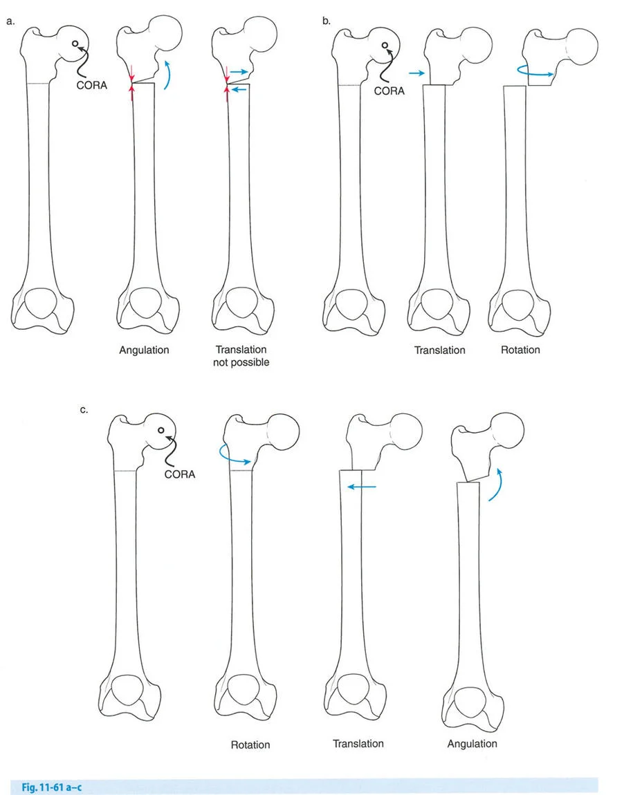
Paley Osteotomy Rules for Hardware Placement
Understanding Paleys Osteotomy Rules is absolutely non-negotiable for frame planning and execution. These three rules dictate the geometric relationship between the Center of Rotation of Angulation, the Axis of Correction of Angulation, and the physical bone cut.
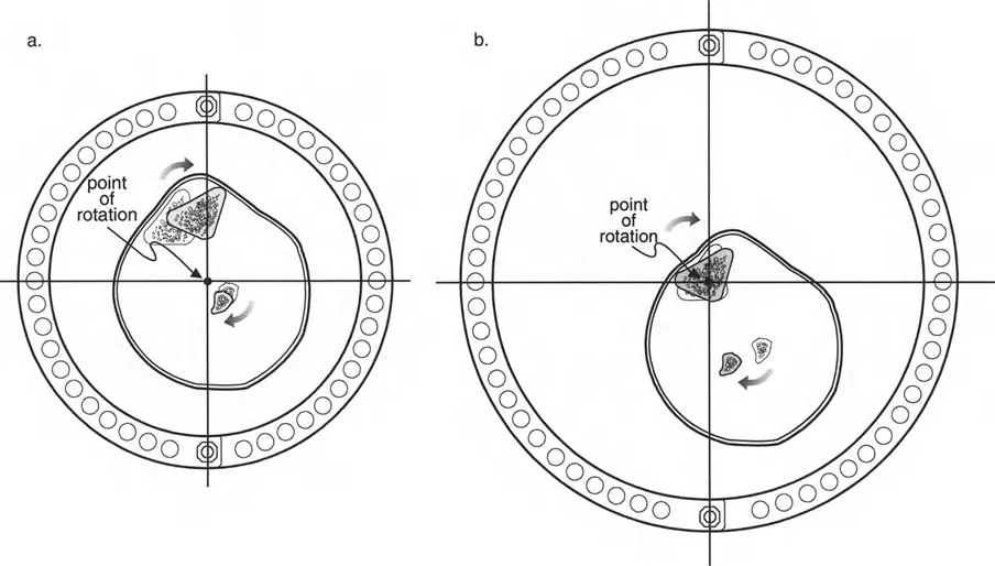
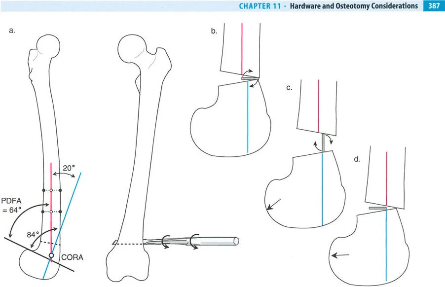
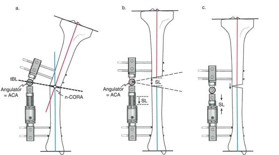
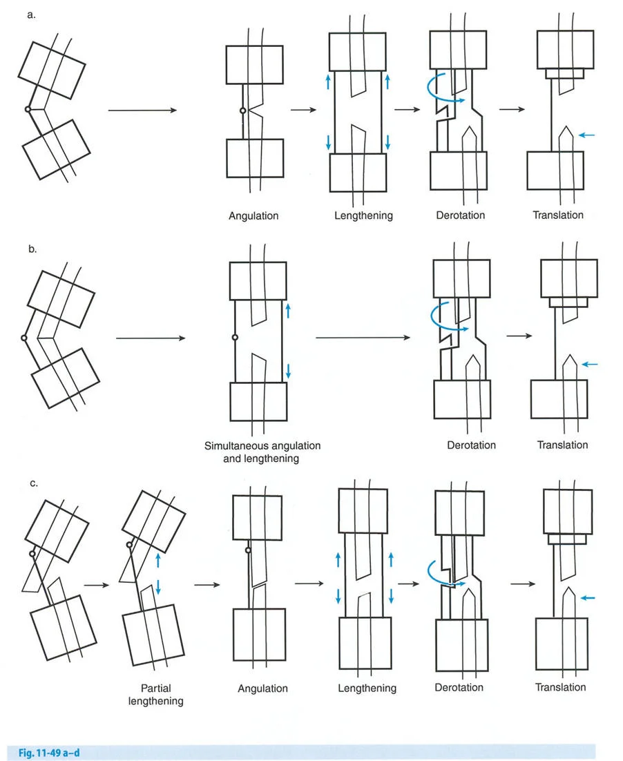
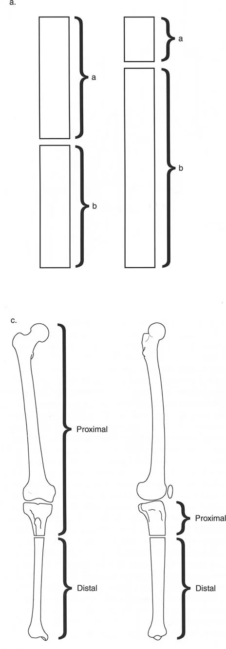
Osteotomy Rule One
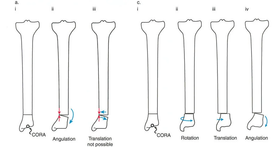
When the osteotomy and the Axis of Correction of Angulation both pass precisely through the Center of Rotation of Angulation, the bone ends will angulate without any translation. The mechanical axis is perfectly restored, and the bone ends remain perfectly apposed.
This creates a classic opening wedge or closing wedge correction. This is the ideal scenario for diaphyseal deformities where the bone quality is robust and the soft tissue envelope allows for a cut exactly at the apex of the deformity.
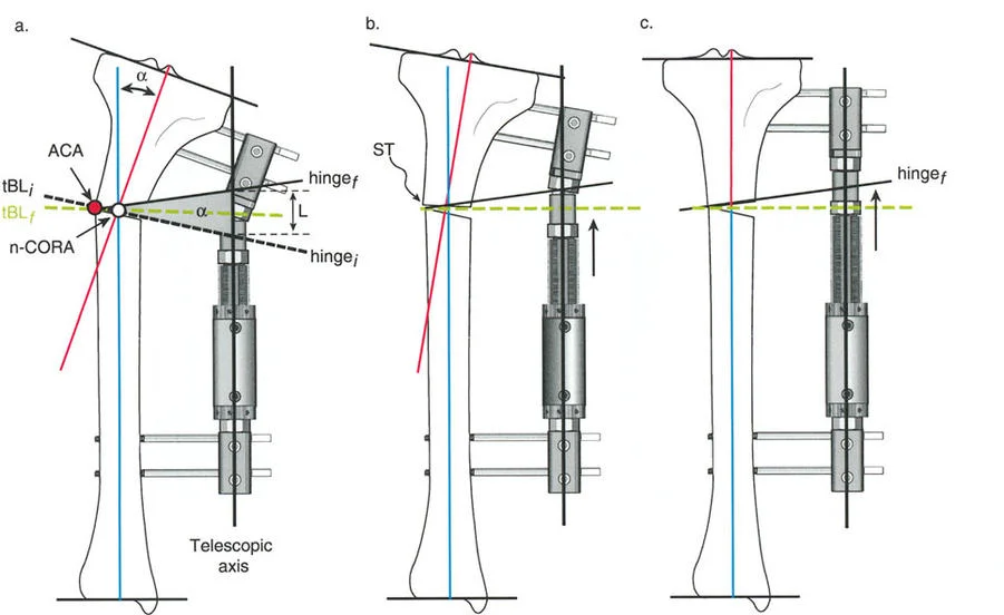
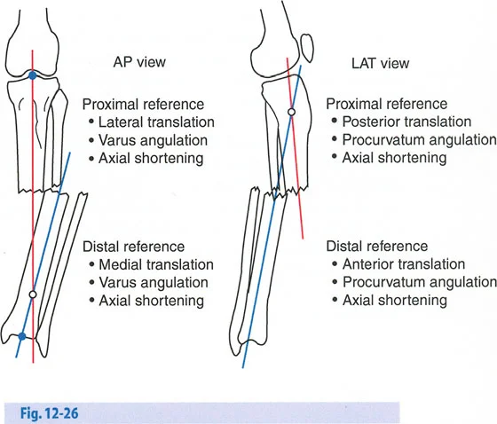
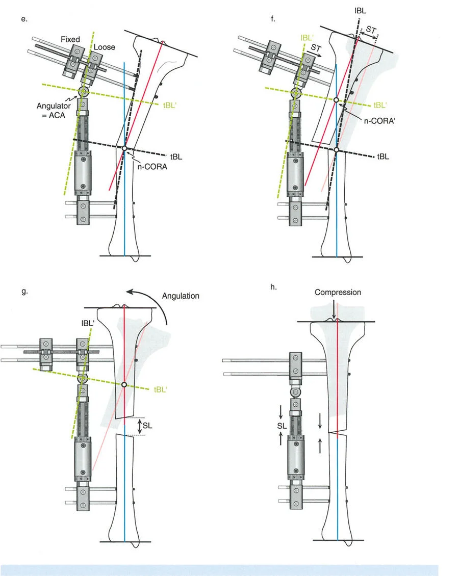
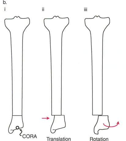
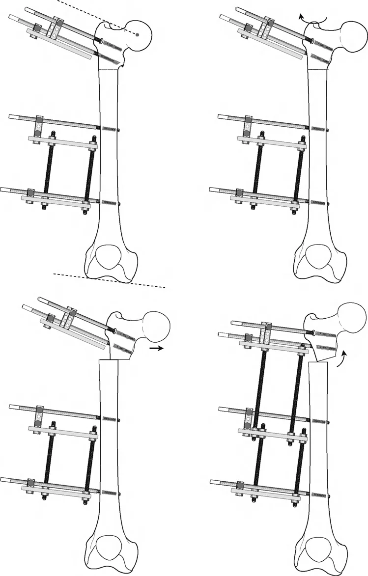
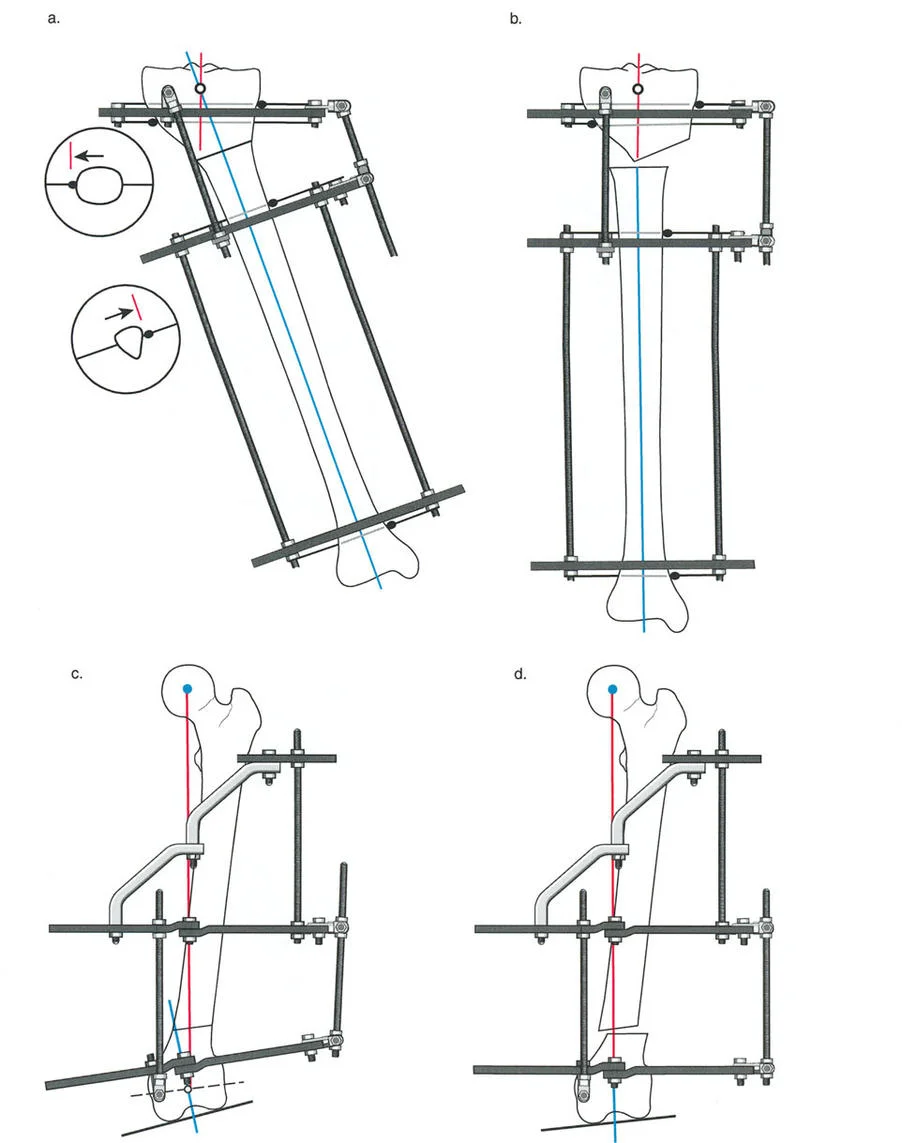
Osteotomy Rule Two
When the Axis of Correction of Angulation passes through the Center of Rotation of Angulation, but the physical osteotomy is performed at a different level, the bone ends will angulate and undergo a calculated, deliberate translation to realign the mechanical axis.
This rule is frequently utilized when the Center of Rotation of Angulation is located in an area of poor bone quality, compromised skin, or dangerously close to a joint line. The hinges are placed at the Center of Rotation of Angulation, but the bone is cut at a safer, more biologically friendly location. As the hinges open, the mechanical axis is restored, but the bone ends will slide and translate relative to each other.
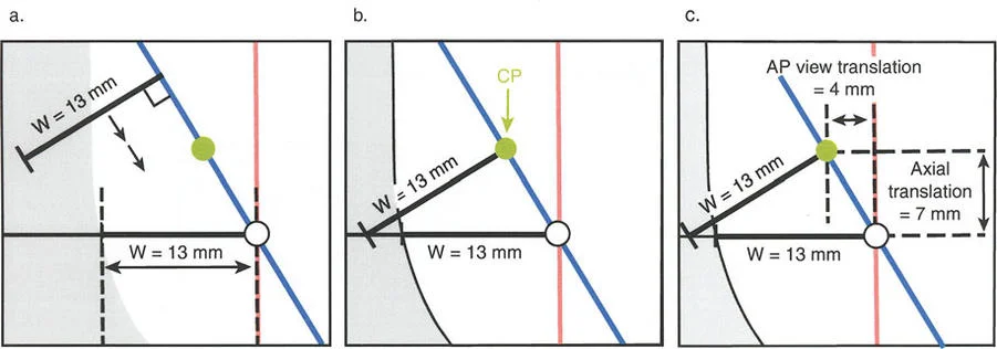
Osteotomy Rule Three
When the osteotomy passes through the Center of Rotation of Angulation, but the Axis of Correction of Angulation is placed outside the Center of Rotation of Angulation, a new, iatrogenic translation deformity will be created.
This is a common pitfall of poorly planned hinge placement. The mechanical axis will not be restored, and the surgeon will inadvertently create a secondary deformity that requires further complex correction. Rule Three is generally considered an error in preoperative planning and must be avoided.
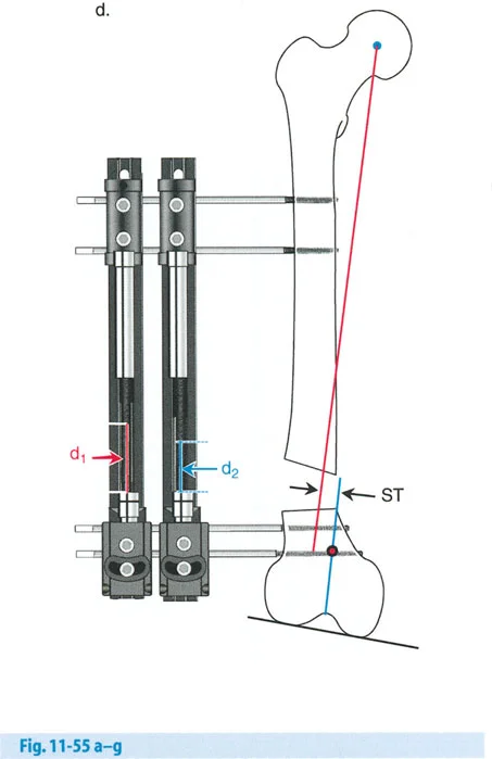
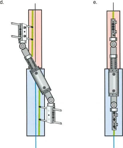
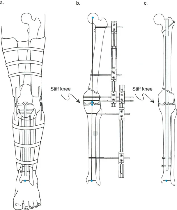
Juxta Articular Hinge Assemblies and Complex Corrections
When dealing with deformities located near a joint line, such as a severe proximal tibia varus seen in Blounts disease, or a distal femoral valgus deformity, the placement of the hardware becomes geometrically constrained. The biological requirement to preserve the joint capsule, avoid intra-articular pin placement, and prevent septic arthritis frequently forces the surgeon to place the reference ring at a level entirely different from the actual Center of Rotation of Angulation.
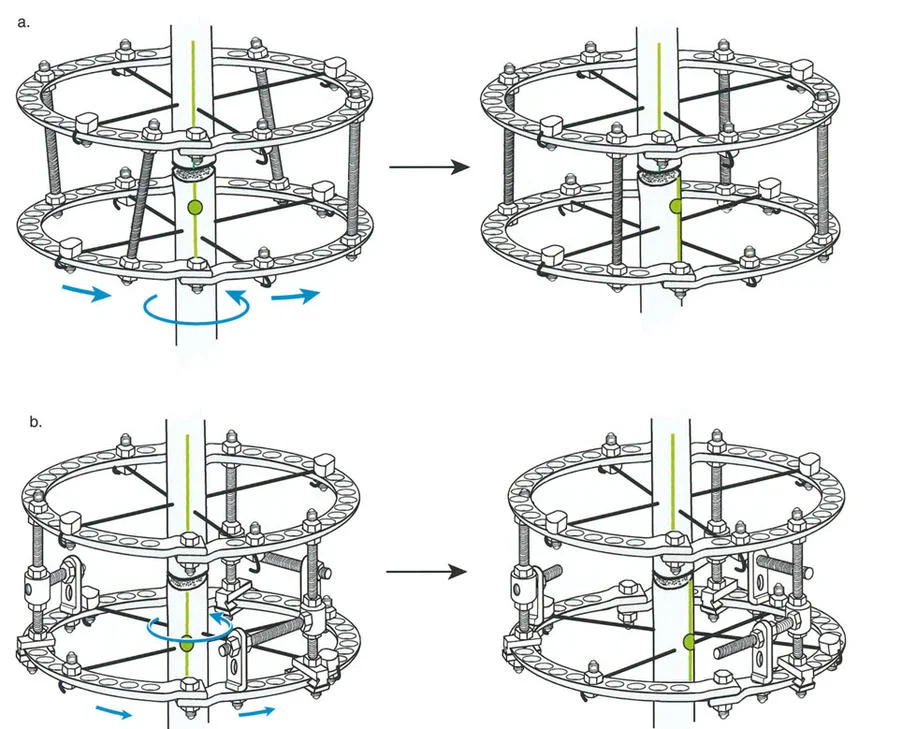
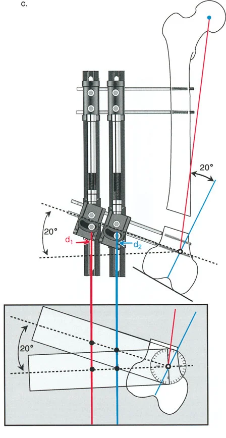
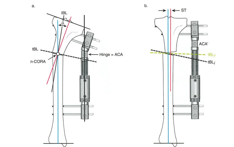
The Challenge of the Juxta Articular Center of Rotation
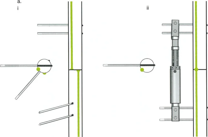
To match the hinge of the external fixator to the exact level of the Center of Rotation of Angulation, the hinge must frequently be built above or below the level of the physical ring. This is known in Paley principles as a juxta-articular hinge assembly.
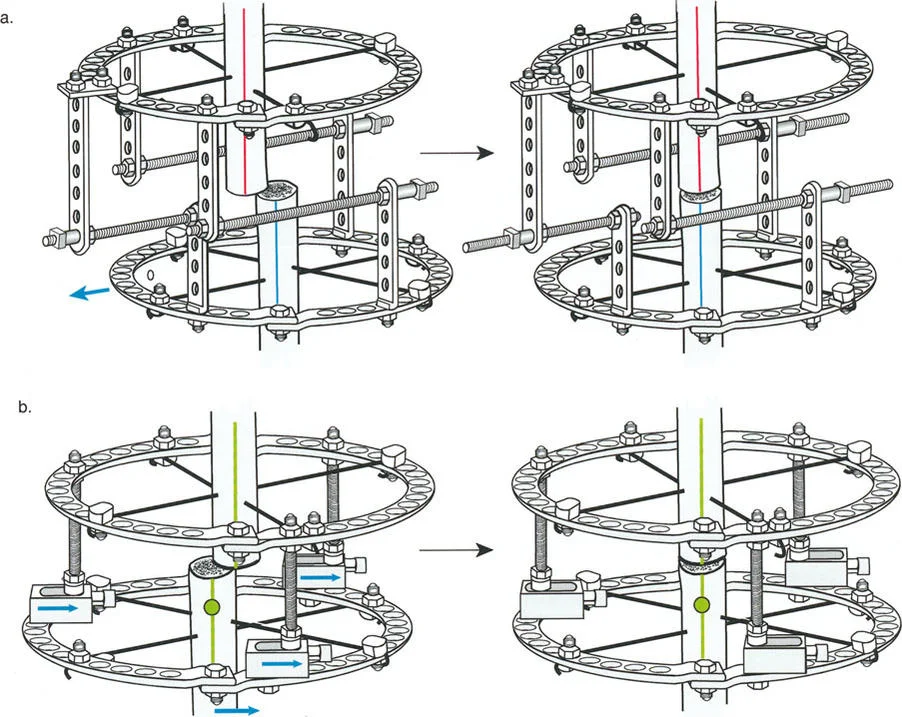
If the Center of Rotation of Angulation is located near the joint line, placing a standard Ilizarov ring at that exact level is impossible without violating the joint space or tethering vital capsular structures. Therefore, the reference ring is fixed to the available metaphyseal or diaphyseal bone. The hinge mechanism is then built out using threaded rods, connection plates, and posts. It is then dropped or elevated to align perfectly with the true geometric Center of Rotation of Angulation.
Executing Rule Two in Juxta Articular Constructs
In juxta-articular constructs, we almost exclusively rely on Osteotomy Rule Two. Because we cannot safely cut the bone precisely at the joint line, we cut lower in the metaphysis or upper diaphysis. After the angular correction is achieved via the dropped hinges, the mechanical axis lines are realigned perfectly, but the osteotomy site bone ends translate relative to each other. This translation must be anticipated and managed mechanically.
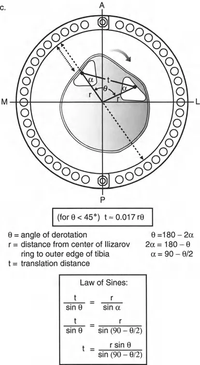
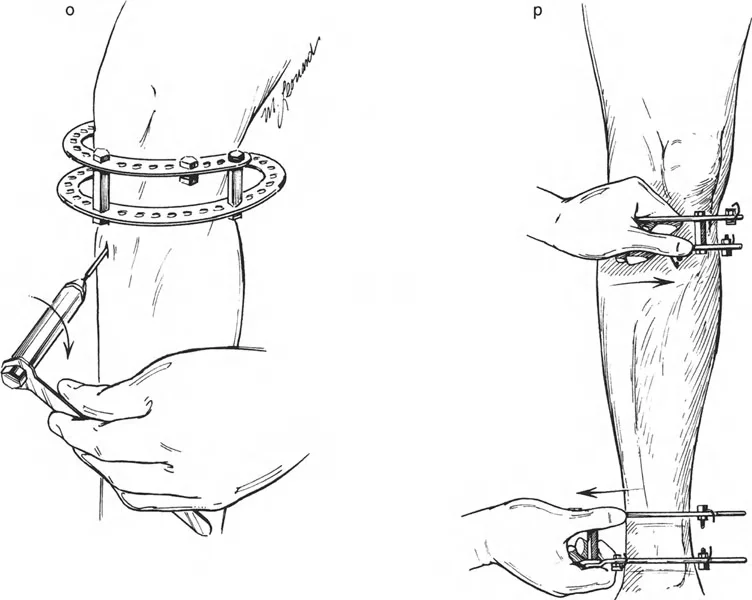
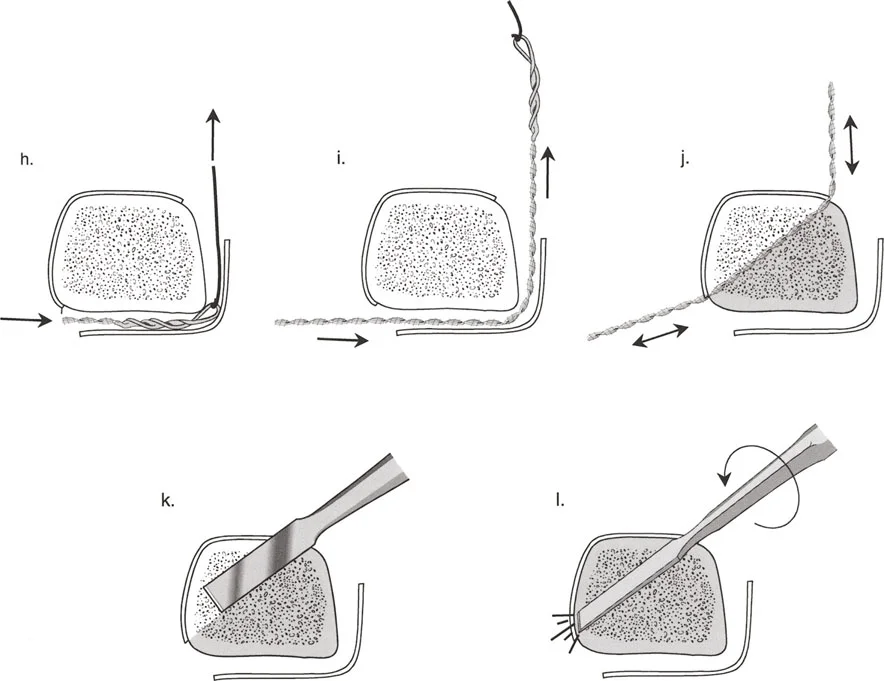
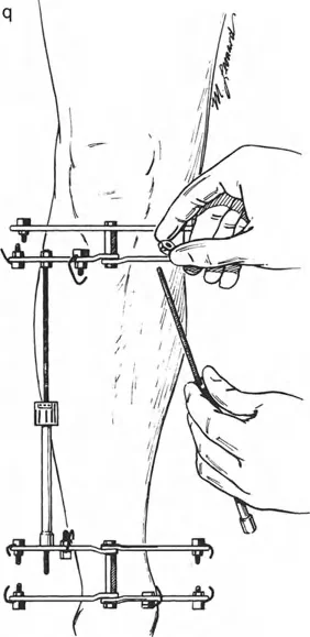
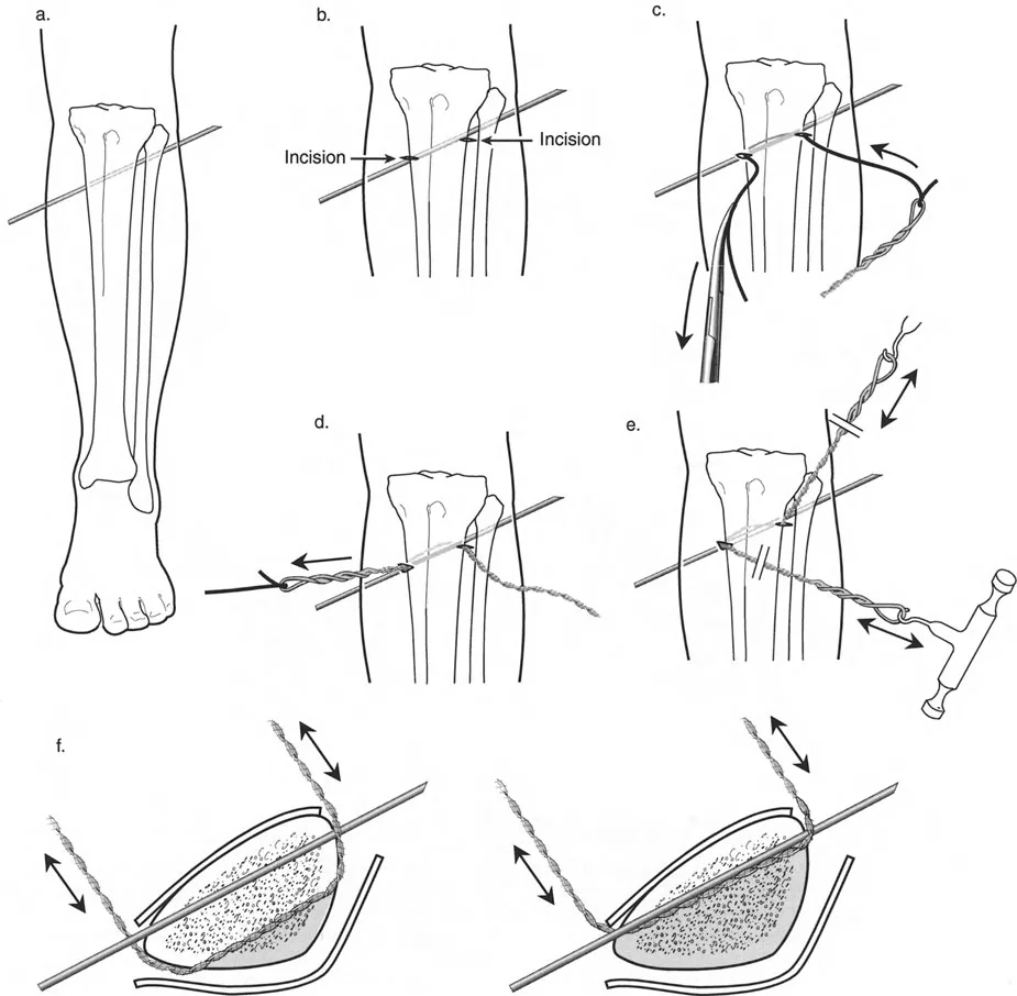
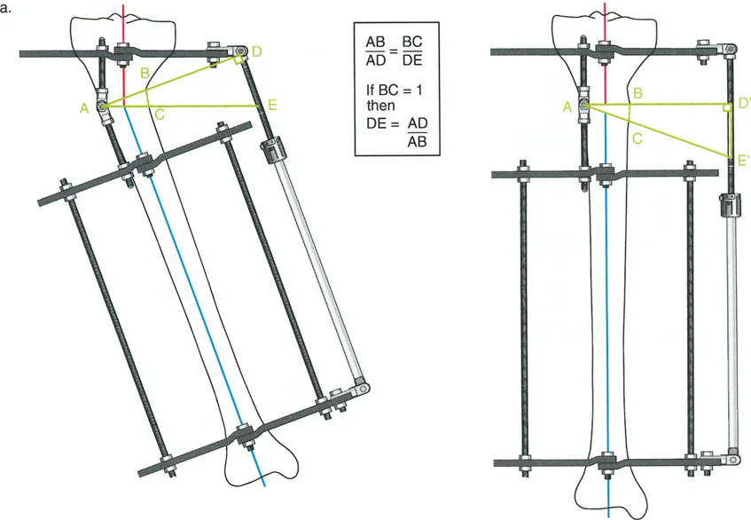
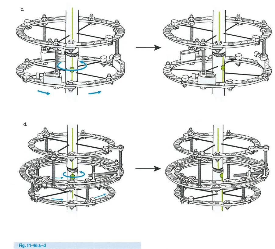
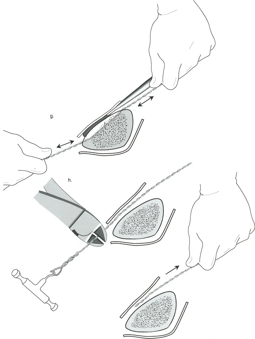
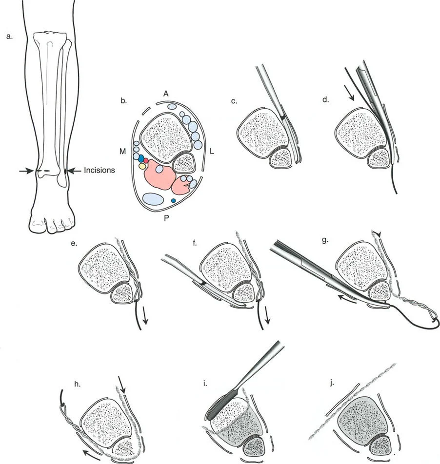
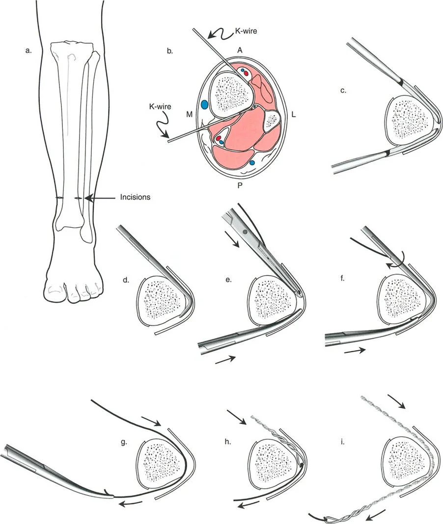
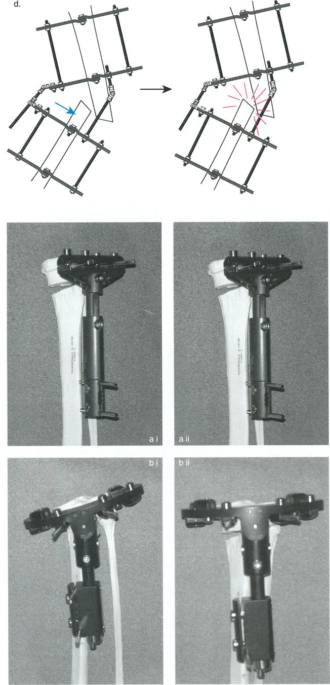
Managing Translation with Wire and Pin Constraints
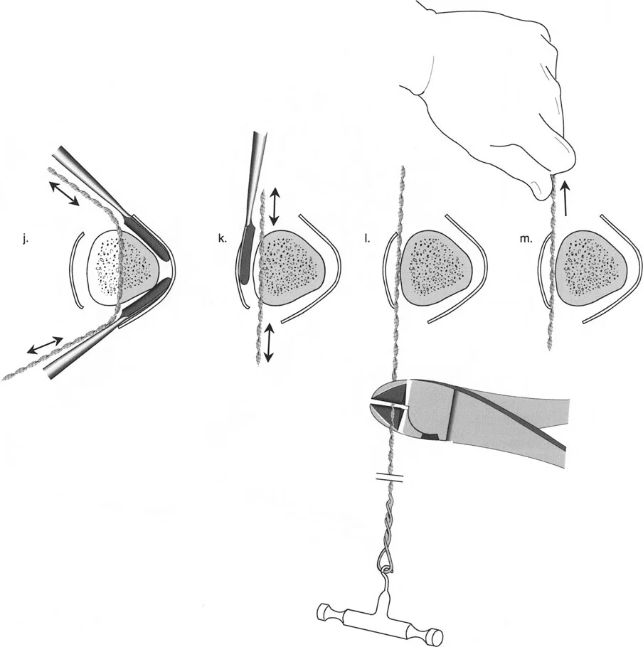
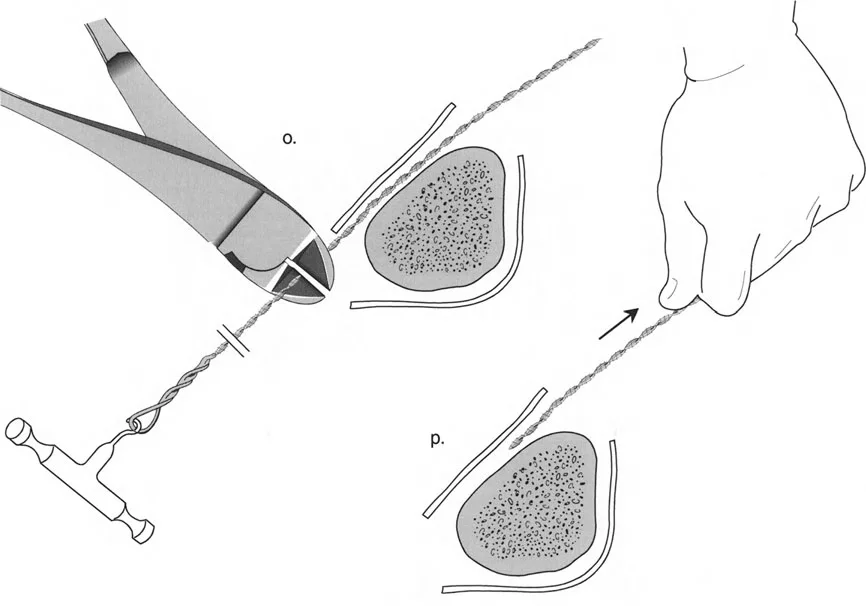
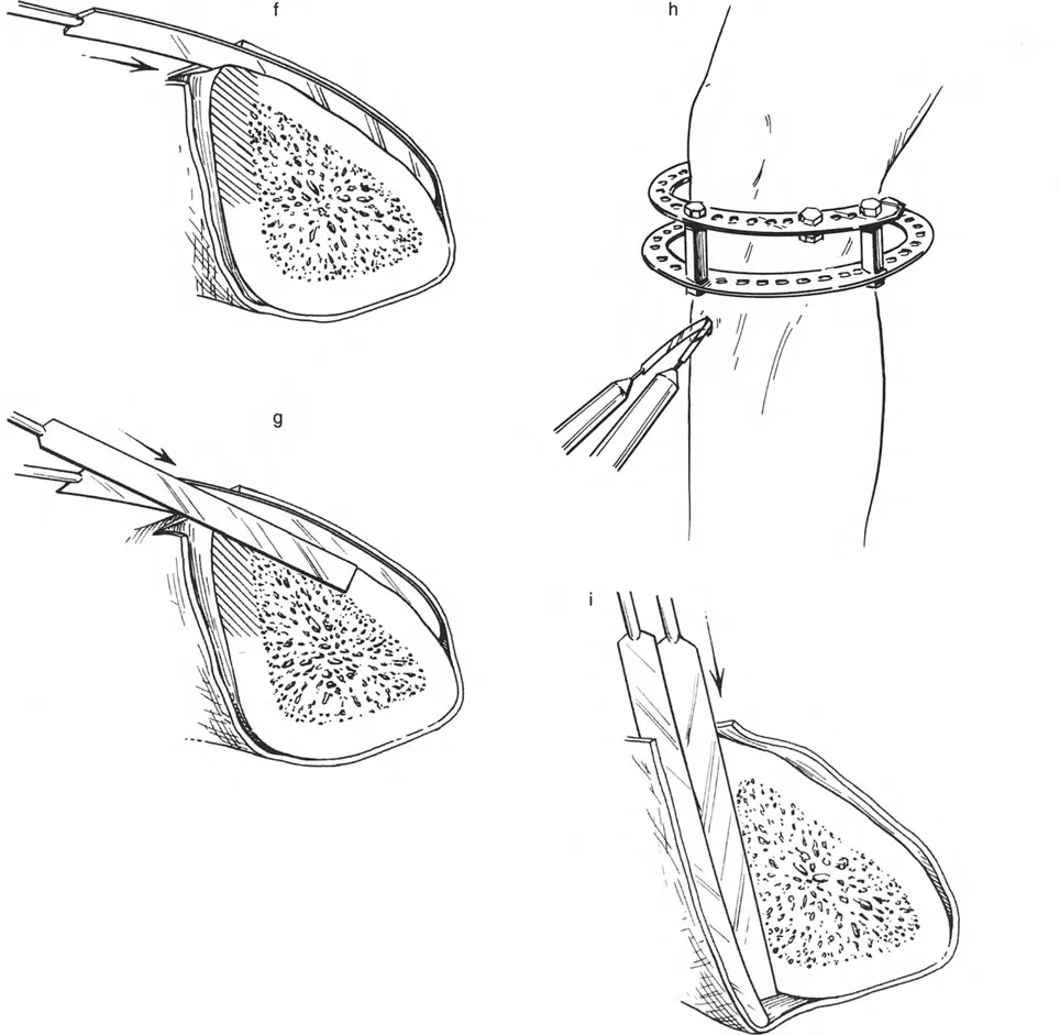
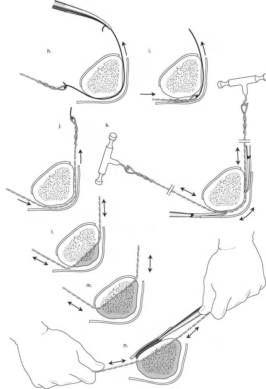
To effect the necessary, deliberate translation smoothly with an all-wire circular frame under Osteotomy Rule Two, specific wire configurations are required. Standard smooth wires will simply slide through the bone, failing to pull the bone segment into its new translated position.
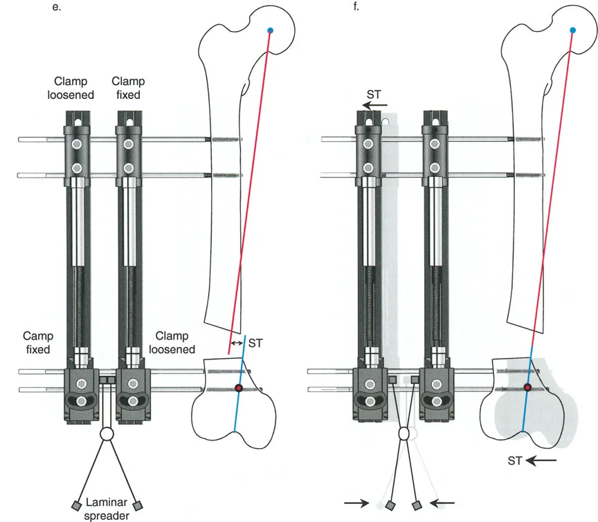
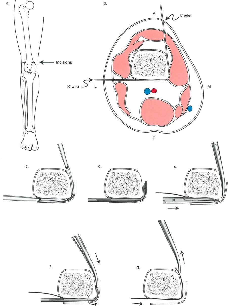
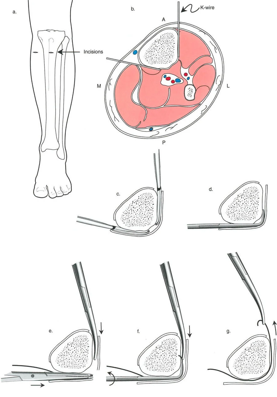
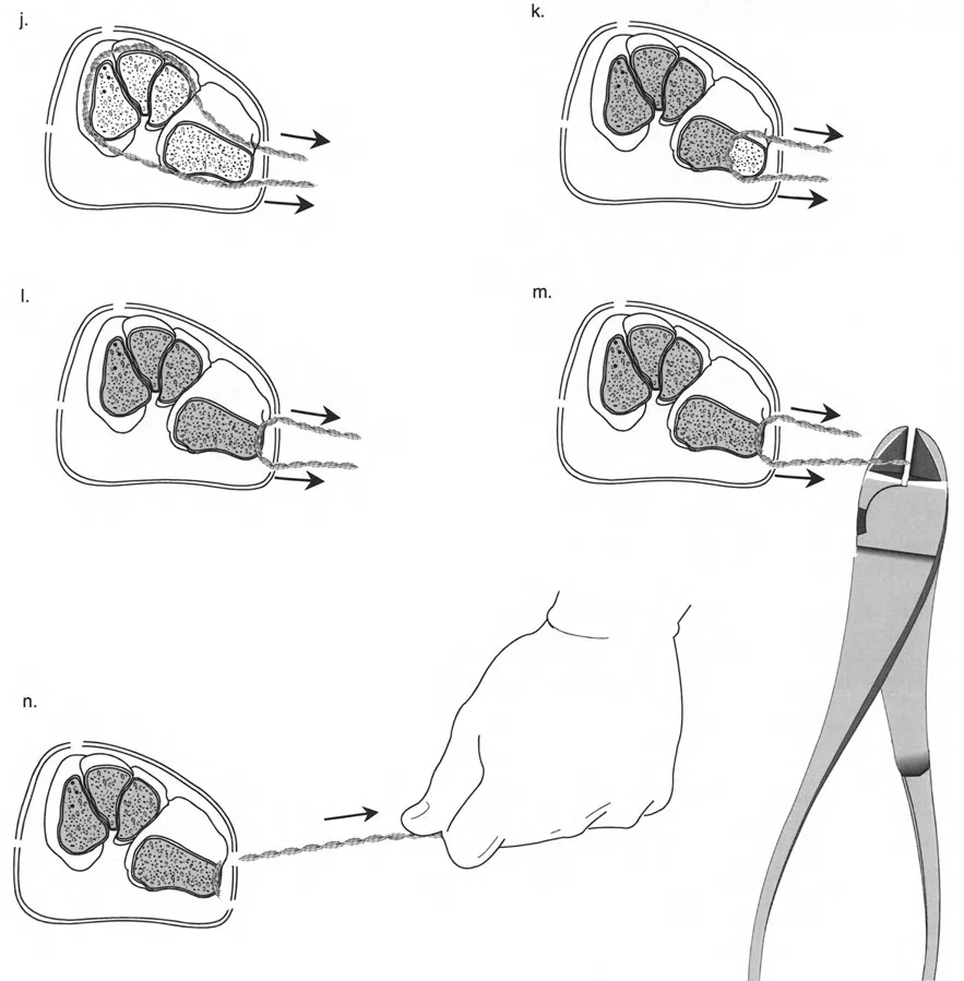
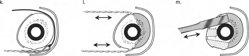
The Role of Olive Wires
Counter-opposed olive wires are mandatory for managing translation. An olive wire features a small metallic bead that rests against the near cortex of the bone. These wires act as dynamic pulling forces, dragging the bone segment along the ring as the hinges open.
Without olive wires, the bone would simply stay stationary while the ring shifted, leading to hardware failure, wire cut-out, and failure to correct the mechanical axis. Proper tensioning of these olive wires ensures that the bone follows the mechanical path dictated by the hinge assembly.
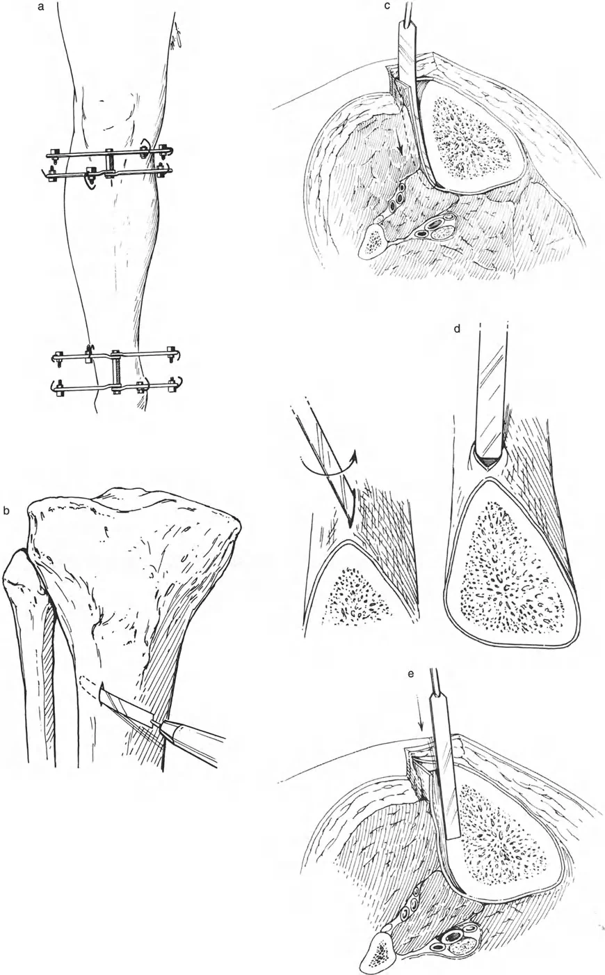
Half Pin Utilization
In modern deformity correction, hybrid frames utilizing both tensioned wires and hydroxyapatite-coated half-pins are common. When using half-pins in a Rule Two correction, the pins provide rigid cantilever support that forces the bone segment to translate with the ring. The surgeon must ensure that the half-pins are placed in the correct plane to avoid bending forces during the translation phase.
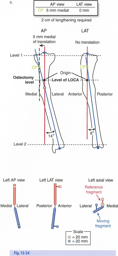
Step by Step Preoperative Planning Guide
The success of any deformity correction is dictated long before the patient enters the operating room. A systematic approach to preoperative planning ensures mathematical certainty.
- Obtain Proper Imaging: Acquire weight-bearing, full-length anterior-posterior and lateral radiographs of both lower extremities. Ensure the patellae are facing strictly forward to control for rotational variables.
- Perform the Malalignment Test: Draw the mechanical axis line from the center of the femoral head to the center of the ankle plafond. Measure the Mechanical Axis Deviation at the knee joint.
- Determine the Origin of Deformity: Measure the mechanical Lateral Distal Femoral Angle and the Medial Proximal Tibial Angle. Compare these to normal values to determine if the deformity is femoral, tibial, or combined.
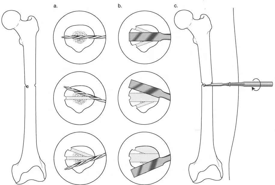
- Locate the Center of Rotation of Angulation: Draw the proximal anatomical/mechanical axis and the distal anatomical/mechanical axis. The intersection of these lines is the Center of Rotation of Angulation.
- Select the Osteotomy Site: Based on bone quality and soft tissue, decide if you will cut at the Center of Rotation of Angulation (Rule One) or away from it (Rule Two).
- Design the Frame Construct: Template the ring sizes, ensuring at least two fingerbreadths of clearance between the ring and the soft tissue to accommodate postoperative swelling. Plan the hinge placement exactly at the Center of Rotation of Angulation.
Postoperative Management and Regenerate Bone Care
The surgical application of the frame is merely the beginning of the deformity correction process. The postoperative phase requires meticulous attention to detail to ensure the regenerate bone consolidates properly and complications are mitigated.
Monitoring the Distraction Phase
During the active distraction phase, the patient must be seen frequently in the clinic. Radiographs should be taken every ten to fourteen days to assess the quality of the regenerate bone. The surgeon must look for signs of premature consolidation, which presents as an overly dense, bridging callus that resists further distraction. If this occurs, the distraction rate may need to be increased, or the bone may need to be re-osteotomized.
Conversely, if the regenerate gap appears radiolucent with cystic changes, the distraction rate is too fast. The surgeon must employ the accordion technique, temporarily compressing the gap for several days to stimulate angiogenesis, before resuming distraction at a slower rate.
Pin Site Care and Physical Therapy
Pin tract infections are the most common complication in external fixation. A strict protocol of daily pin site cleaning with chlorhexidine or saline is required. Oral antibiotics should be initiated at the first sign of erythema to prevent deep osseous infection.
Simultaneously, aggressive physical therapy is mandatory. The tension-stress effect applies not only to bone but to the surrounding soft tissues. If the muscles and tendons are not actively stretched through physical therapy, severe joint contractures will develop, compromising the ultimate functional outcome of the limb reconstruction.
By adhering strictly to the geometric principles of Paley and the biological laws of Ilizarov, the orthopedic surgeon can navigate the most complex deformity corrections with confidence, restoring both anatomy and function to the patient.
!!! info "Academic Resource & Medical Review"
This academic resource was prepared and medically reviewed by Prof. Dr. Mohammed Hutaif, Consultant Orthopedic & Spine Surgeon. It is formulated specifically for medical students, orthopedic residents, and surgeons preparing for high-stakes board examinations (AAOS, FRCS Tr & Orth, Arab Board).
!!! warning "Disclaimer"
The surgical techniques, classifications, and clinical guidelines presented herein are for educational and academic review purposes only. They are not intended to replace institutional protocols or independent clinical judgment.
You Might Also Like