The Single-Cut Inclined Osteotomy: Mastering Angulation-Rotation Deformities with Paley's Principles
Key Takeaway
The single-cut inclined osteotomy is a surgical technique for correcting complex angulation-rotation deformities. By making an osteotomy perpendicular to a single inclined axis, it simultaneously corrects both angular and rotational components. This method, based on Paley's principles, maintains bone contact and restores the mechanical axis.
Introduction to Complex Three Dimensional Deformity Correction
In the realm of orthopedic deformity correction, addressing a uniplanar deformity such as an isolated varus or valgus angulation is a fundamental and foundational skill. However, clinical reality rarely presents itself in a single, easily manageable plane. When a patient presents with a combination of coronal or sagittal plane angulation coupled with axial plane rotation, the surgeon faces a complex, three-dimensional spatial puzzle. These are clinically classified as Angulation Rotation Deformities.
Historically, orthopedic surgeons approached these combined deformities in a staged manner or utilized complex, multi-planar step-cut osteotomies. Often, correcting the angulation first and the rotation second led to a catastrophic loss of bone contact, inherent biomechanical instability, delayed union, or frank nonunion. The surgical morbidity associated with these traditional techniques necessitated a paradigm shift in how we understand bone geometry.
The evolution of Dr. Dror Paley’s principles revolutionized this approach. From a conceptual and biomechanical standpoint, any combined angulation and rotation deformity can be mathematically resolved into a single axis of rotation. If an osteotomy is made perpendicular to this specific inclined axis, rotating the distal segment around that axis will simultaneously correct both the angular and rotational components while maintaining absolute cortical contact between the osteotomy surfaces.
This masterclass will deconstruct the biomechanics, mathematical calculations, and surgical execution of the single-cut inclined osteotomy for angulation rotation deformities, utilizing classic analogies and Paley's foundational principles to elevate your surgical acumen.
Foundational Paley Principles CORA and the Mechanical Axis
Before attempting to execute an inclined osteotomy, a surgeon must have absolute mastery over the Center of Rotation of Angulation (CORA). Correcting a three-dimensional deformity is fundamentally useless if the osteotomy induces a secondary translation deformity that shifts the Mechanical Axis Deviation (MAD).
Understanding Mechanical Axis Deviation
The mechanical axis of the lower extremity is defined by a line drawn from the center of the femoral head to the center of the ankle joint (tibial plafond). In a normal, well-aligned lower extremity, this line should pass just medial to the center of the knee joint. The distance from the center of the knee to this mechanical axis line is the Mechanical Axis Deviation.
When an angulation rotation deformity exists, the MAD is invariably altered, leading to asymmetrical joint loading, early-onset osteoarthritis, and compromised gait biomechanics. The primary goal of any osteotomy is the complete restoration of the MAD to its physiologic baseline.
Joint Orientation Angles and Radiographic Analysis
To find the CORA and plan the correction, the surgeon must rely on standard Joint Orientation Angles. These angles define the relationship between the mechanical or anatomic axes of the long bones and their respective joint lines.
| Joint Orientation Angle | Abbreviation | Normal Physiologic Range |
|---|---|---|
| Mechanical Lateral Distal Femoral Angle | mLDFA | 85° to 90° (Average 87°) |
| Mechanical Proximal Tibial Angle | MPTA | 85° to 90° (Average 87°) |
| Joint Line Convergence Angle | JLCA | 0° to 2° |
| Lateral Distal Tibial Angle | LDTA | 86° to 92° (Average 89°) |
| Mechanical Lateral Proximal Femoral Angle | mLPFA | 85° to 95° (Average 90°) |
By plotting these normal angles on the proximal and distal joint lines of a deformed bone, the surgeon can draw the proximal and distal mechanical axes. The intersection of these two lines dictates the exact location of the CORA.
The Importance of the CORA in Three Dimensional Corrections
The CORA is the critical intersection point of the proximal and distal mechanical axes of a deformed bone. When planning an inclined osteotomy for angulation rotation deformities, the osteotomy plane must be meticulously planned in relation to the CORA.
If we apply Paley's Osteotomy Rules to the inclined axis, we establish the fundamental laws of deformity correction:
- Osteotomy Rule One If the osteotomy and the hinge (axis of rotation) both pass through the CORA, angulation and rotation are corrected without translation. The mechanical axis is perfectly restored.
- Osteotomy Rule Two If the hinge passes through the CORA, but the osteotomy is made at a different longitudinal level, the deformity is corrected, but the bone ends will translate relative to one another. This is often used intentionally when the CORA is located in the metaphyseal-diaphyseal junction, but the bone quality dictates a diaphyseal cut.
- Osteotomy Rule Three If neither the hinge nor the osteotomy passes through the CORA, a secondary translation deformity is created, leading to a new, iatrogenic mechanical axis deviation.
Therefore, the precise identification of the CORA using joint orientation angles is the mandatory first step. The single-cut inclined osteotomy is mathematically elegant, but if executed at the wrong longitudinal level of the bone without accounting for Paley's rules, it will result in an iatrogenic zig-zag deformity.
Clinical Pearls for Identifying the CORA
- Always obtain full-length, weight-bearing, standing radiographs (teleoroentgenograms) with the patella facing strictly forward to control for rotation.
- In cases of severe rotation, orthogonal views of the local joint (e.g., a true AP of the knee and a true AP of the ankle) are required to accurately measure the mLDFA and MPTA independently.
- Multi-apical deformities will have multiple CORAs. You must determine if a single osteotomy can address the entire deformity or if multiple osteotomies are required.
Visualizing the Inclined Axis The Necktie Analogy
Visualizing a single axis that corrects two different planes of deformity is notoriously difficult for the human brain. The spatial reasoning required to look at a twisted, bowed tibia and conceptualize a single planar cut is immense. To bridge this cognitive gap, we rely on the classic Necktie Analogy popularized in deformity correction education.
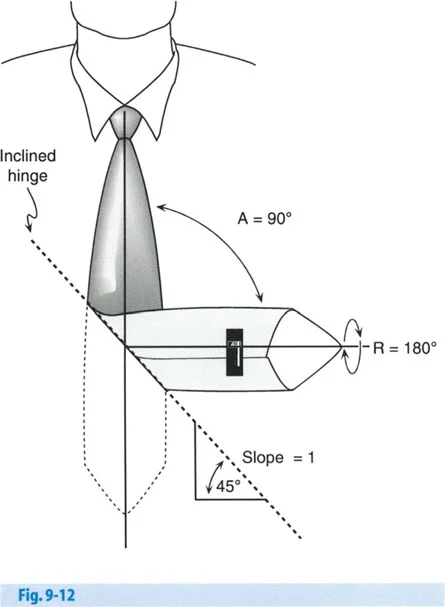
Imagine a standard men's necktie lying completely flat on a table. The tie represents a long bone in perfect, physiologic alignment. Now, fold the tie in the middle so that the back side of the lower half of the tie is lying flat across the chest.
By performing this single, simple fold, you have instantly created two distinct, mathematically linked deformities:
1. A ninety degree Angulation Deformity (the tie now points to the side instead of straight down).
2. A one hundred and eighty degree Rotation Deformity (the back of the tie is now facing forward).
The line of the fold you just made is precisely the inclined axis.
Breaking Down the Necktie Mathematics
As seen in the diagram above, the angulation rotation deformity of the tie was produced by folding it around a longitudinally inclined axis. Because the fold created the deformity, rotating the distal limb back around that exact same fold line will simultaneously correct both the ninety degree angulation and the one hundred and eighty degree rotation.
Let's look at the mathematical calculation of the orientation of this inclined axis based on the diagram. We define our variables as follows:
* A represents Angulation, which is ninety degrees.
* R represents Rotation, which is one hundred and eighty degrees.
Calculating the Orientation
The orientation of the axis relative to the plane of the deformity is calculated as half of the rotational deformity.
* Orientation equals R divided by 2
* Orientation equals 180° divided by 2, which equals 90°
Calculating the Inclination Slope
The slope of the inclination is determined by the tangent of half the angulation divided by the tangent of half the rotation. Alternatively, using sine functions as shown in the classic Paley text, the formula is:
* Inclination slope equals $\sin(R/2) / \tan(A/2)$
* Substitute the values: $\sin(180/2) / \tan(90/2)$
* Simplify the trigonometric functions: $\sin(90°) / \tan(45°)$
* Calculate the values: $1 / 1 = 1$
A line that has a mathematical slope of 1 is exactly 45° from the horizontal line. Therefore, the inclination angle of the hinge is 45°.
While the necktie analogy is brilliant for proving that a single axis exists and can resolve two planes of deformity, it has a major limitation. A necktie is a flat, two-dimensional object. Bones are three-dimensional cylinders with cortical thickness, medullary canals, and complex soft tissue envelopes. Folding a flat plane does not fully clarify how to take an oscillating saw to a cylindrical bone. For that, we must move to the operating room simulation lab.
Transitioning to Cylindrical Bone The Banana Analogy
To truly understand how to execute the inclined osteotomy, we must practice on a three-dimensional object that naturally possesses an angular deformity. The banana is the perfect, readily available surgical model for this exercise.
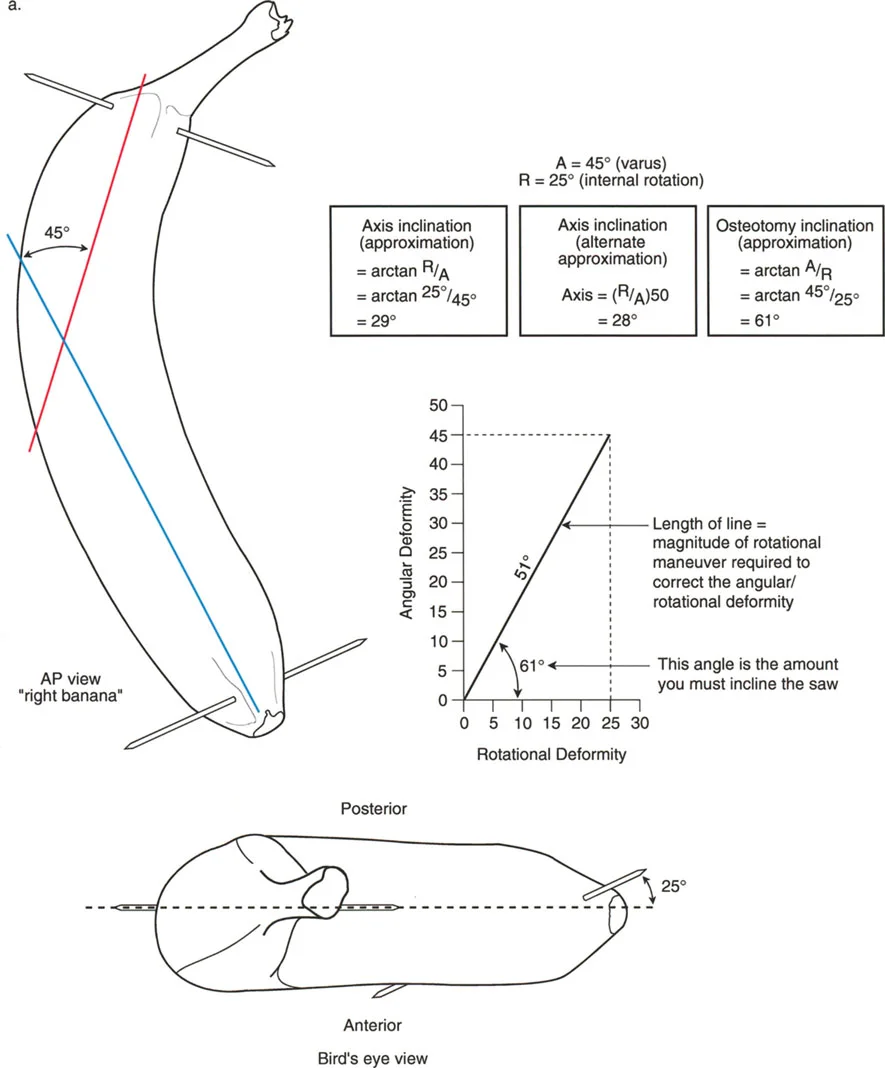
The natural curve of the banana represents the angular deformity, such as a severe varus bow in a tibia or femur. By manipulating this curved cylinder, we can simulate the exact steps required in the operating theater.
Setting Up the Banana Simulation
- Marking the Anterior Cortex Use a surgical marker to draw a straight longitudinal line down the convex side of the banana. This represents the anterior crest of the tibia or the anterior cortex of the femur.
- Identifying the CORA Find the apex of the banana's curve. This represents the Center of Rotation of Angulation. Make a transverse mark at this apex.
- Drawing the Osteotomy Plane Instead of drawing a straight transverse line across the banana, draw an oblique line passing through the CORA mark. This line should be inclined at a 45-degree angle to the longitudinal axis of the banana.
- Executing the Osteotomy Use a scalpel to cut completely through the banana along this inclined plane. Ensure the cut is perfectly planar; any deviation will result in a loss of contact during rotation.
- Performing the Correction Hold the proximal half of the banana steady. Take the distal half and rotate it exactly 180 degrees around the axis perpendicular to your cut.
Analyzing the Simulation Results
Once you have rotated the distal segment 180 degrees, observe the final construct. You will notice three profound changes:
First, the inherent curve (angulation) of the banana has been completely neutralized. The banana is now perfectly straight.
Second, the longitudinal line you drew on the anterior cortex is now on the posterior side of the distal segment, proving that a 180-degree rotational correction has occurred.
Third, and most importantly for bone healing, the two cut surfaces of the banana are in 100% flush contact. There are no gaps, no step-offs, and no loss of structural apposition.
This simulation proves that a single inclined cut can correct both angulation and rotation while maximizing the surface area for osteogenesis.
Preoperative Planning for the Inclined Osteotomy
Mastery of the single-cut inclined osteotomy begins long before the patient enters the operating room. Meticulous preoperative planning is the distinguishing factor between an expert deformity surgeon and a novice.
Step One Radiographic Assessment
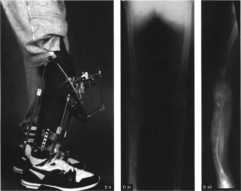
Obtain high-quality, standardized radiographs. This includes a standing AP full-length leg radiograph, a standing lateral full-length radiograph, and dedicated AP and lateral views of the affected bone segment. CT scans with 3D reconstructions and rotational profiles (measuring femoral anteversion and tibial torsion) are highly recommended for complex cases.
Step Two Identifying the Deformity Parameters
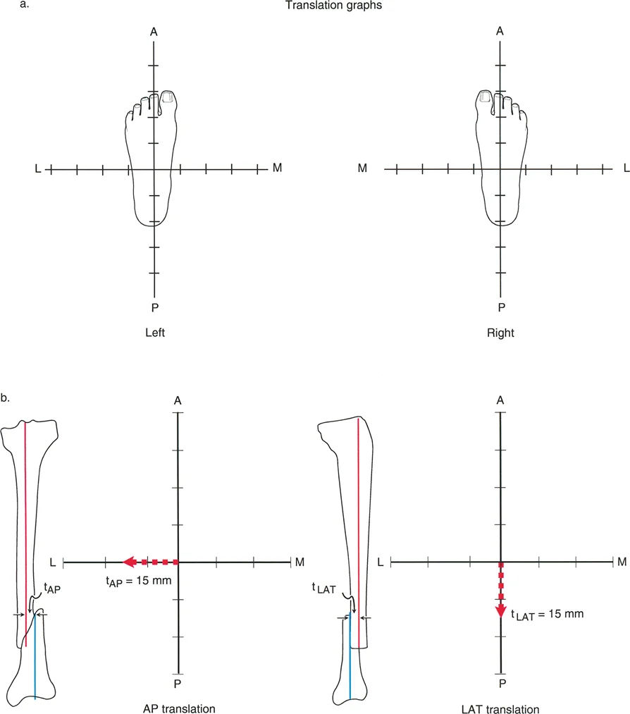
Determine the exact magnitude of the angulation (A) in degrees using the mechanical axis lines and the CORA. Next, determine the exact magnitude of the rotational deformity (R) in degrees using clinical examination (e.g., thigh-foot angle, transmalleolar axis) and CT rotational profiles.
Step Three Calculating the Inclination Angle
Utilize the Paley formula to calculate the inclination angle.
Inclination Angle = arctan ( $\sin(R/2) / \tan(A/2)$ )
For example, if a patient has a 20-degree varus deformity (A=20) and a 30-degree internal rotation deformity (R=30):
* R/2 = 15°
* A/2 = 10°
* $\sin(15°) \approx 0.258$
* $\tan(10°) \approx 0.176$
* $0.258 / 0.176 \approx 1.465$
* arctan(1.465) $\approx$ 55.7°
The osteotomy cut must be inclined at approximately 56 degrees to the transverse plane of the bone.
Step Four Determining the Orientation of the Cut
The orientation of the inclined plane dictates the direction of the cut. The axis of the cut must be oriented such that rotating the distal segment corrects both deformities simultaneously. The orientation angle is always R/2 relative to the plane of maximum angulation.
Key Takeaways for Preoperative Planning
- Rule of Thumb The larger the rotational deformity relative to the angular deformity, the steeper the inclination angle of the osteotomy will be.
- Template Overlay Always use digital templating software to simulate the cut and rotation before surgery. This allows you to visualize the final bone apposition and plan your hardware placement.
- Hardware Conflicts An inclined osteotomy creates a long, oblique fracture line. You must plan your fixation (intramedullary nail, plate, or external fixator) to accommodate this specific geometry. A long oblique cut may interfere with standard locking screw trajectories.
Surgical Execution of the Single Cut Inclined Osteotomy
Transitioning from the preoperative template to the operating room requires precision, patience, and strict adherence to the calculated parameters. The following steps outline the surgical execution of the inclined osteotomy.
Patient Positioning and Fluoroscopy
Position the patient supine or lateral, depending on the bone involved and the planned fixation. Ensure that the C-arm fluoroscopy unit can freely visualize the entire length of the bone in both AP and lateral planes. Absolute control over the limb's rotation during imaging is critical; use the patella or the ankle mortise as your rotational landmarks.
Placing the Axis Guide Wire
The most critical step in the procedure is the placement of the initial guide wire. This wire represents the axis of rotation and dictates the plane of the osteotomy.
1. Identify the CORA under fluoroscopy.
2. Insert a rigid Steinmann pin or Kirschner wire through the bone at the exact CORA.
3. The pin must be inserted at the calculated inclination angle (e.g., 56 degrees from our previous example) and at the calculated orientation angle.
4. Verify the pin placement in multiple fluoroscopic views. If the pin is off by even a few degrees, the resulting correction will be imperfect, leaving residual angulation or rotation.
Executing the Osteotomy Cut
Once the guide wire is perfectly positioned, it acts as the reference for the saw cut.
1. Make a longitudinal incision over the planned osteotomy site, taking care to protect neurovascular structures. For a tibial osteotomy, protect the anterior tibial artery and deep peroneal nerve.
2. Elevate the periosteum minimally to preserve the blood supply for bone healing.
3. Use an oscillating saw to make the cut strictly parallel to the guide wire. The saw blade must remain in a single plane. Do not toggle the blade, as this will create a convex or concave surface that prevents flush contact after rotation.
4. Cool the saw blade continuously with sterile saline to prevent thermal necrosis of the bone, which can lead to nonunion.
Achieving the Correction
With the osteotomy complete, the deformity can now be corrected.
1. Apply bone clamps to the proximal and distal segments.
2. Rotate the distal segment around the axis of the guide wire. As you rotate, you will see the angular deformity simultaneously correct.
3. Continue rotating until the pre-calculated rotational correction is achieved (e.g., 30 degrees of external rotation to correct a 30-degree internal rotation deformity).
4. At the end of the rotation, the bone should be perfectly straight in both the coronal and sagittal planes, the rotational profile should be restored, and the osteotomy surfaces should be in 100% contact.
Fixation Strategies and Postoperative Management
Once the deformity is corrected, rigid fixation is required to maintain the alignment and promote osteogenesis. The choice of fixation depends on the surgeon's preference, the location of the osteotomy, and the quality of the bone.
Internal Fixation Options
Intramedullary Nailing
Intramedullary (IM) nails are the gold standard for diaphyseal osteotomies. They provide load-sharing biomechanics and excellent rotational stability when locked proximally and distally. However, passing an IM nail through an inclined osteotomy can be challenging. The reamer may tend to slide down the oblique slope of the cut, causing displacement. To prevent this, the osteotomy must be temporarily clamped or held with provisional reduction wires before reaming. Poller screws (blocking screws) can also be used to guide the reamer and the nail along the central mechanical axis.
Plate Osteosynthesis
Locking plates are ideal for metaphyseal osteotomies where an IM nail would not provide adequate purchase in the short bone segment. Because the inclined osteotomy creates a long oblique surface, interfragmentary lag screws can be placed perpendicular to the osteotomy plane to provide absolute stability and primary bone healing. A neutralization plate is then applied to protect the lag screws from bending and torsional forces.
External Fixation Options
Circular External Fixators (Ilizarov and Taylor Spatial Frame)
While the single-cut inclined osteotomy is designed for acute correction and internal fixation, circular external fixators remain a powerful tool in the deformity surgeon's armamentarium. If the soft tissue envelope is compromised, or if the deformity is too severe for an acute correction without stretching the neurovascular structures, a circular frame can be applied.
The Taylor Spatial Frame (TSF), utilizing hexapod technology and web-based software, allows for gradual correction of residual multi-planar deformities. Even if the inclined osteotomy is performed, the TSF can fine-tune any minor discrepancies in angulation, rotation, or translation postoperatively.
Postoperative Rehabilitation
Postoperative protocols vary based on the fixation method. IM nails and circular frames generally allow for immediate weight-bearing as tolerated, which promotes secondary bone healing through micromotion. Plate fixation may require a period of protected weight-bearing until radiographic callus is visible. Aggressive physical therapy is mandatory to maintain joint range of motion and prevent muscle atrophy.
Complications and Pitfalls in Three Dimensional Correction
Mastering the inclined osteotomy requires an understanding of potential complications and how to avoid them.
Iatrogenic Mechanical Axis Deviation
The most common pitfall is the creation of an iatrogenic translation deformity. This occurs when the surgeon violates Paley's Osteotomy Rules. If the osteotomy is not performed at the true CORA, or if the axis of rotation is miscalculated, rotating the bone will shift the mechanical axis. This results in a zig-zag deformity that alters joint loading and can lead to premature arthritis. Meticulous preoperative templating and intraoperative fluoroscopic verification of the CORA are the only ways to prevent this.
Loss of Cortical Contact
If the saw blade toggles during the cut, or if the inclination angle is incorrect, rotating the distal segment will result in a gap between the bone ends. Loss of cortical contact severely compromises the stability of the construct and drastically increases the risk of delayed union or nonunion. If a gap occurs, the surgeon may need to perform a small shortening resection to achieve flush contact, or utilize autologous bone graft to fill the void.
Neurovascular Compromise
Acute correction of severe deformities places significant tension on the surrounding soft tissues, including nerves and blood vessels. Correcting a severe valgus and external rotation deformity of the tibia, for example, can stretch the common peroneal nerve, leading to a foot drop. Prophylactic surgical decompression of the nerve (e.g., a peroneal nerve release at the fibular neck) should be considered for large magnitude corrections. Postoperatively, the patient must be closely monitored for signs of compartment syndrome or vascular compromise.
Conclusion
Mastering angulation rotation deformities through the single-cut inclined osteotomy represents the pinnacle of orthopedic spatial reasoning and surgical precision. By internalizing Dr. Dror Paley's foundational principles—identifying the CORA, calculating the mechanical axis deviation, and strictly adhering to the osteotomy rules—surgeons can transform a chaotic, three-dimensional problem into a mathematically predictable, single-plane solution.
The transition from the conceptual necktie analogy to the practical banana simulation, and finally to the operating room, requires dedicated study and meticulous preoperative planning. When executed correctly, the inclined osteotomy provides an elegant, biomechanically superior correction that restores physiologic alignment, maximizes bone healing, and ultimately returns the patient to pain-free, functional mobility.
!!! info "Academic Resource & Medical Review"
This academic resource was prepared and medically reviewed by Prof. Dr. Mohammed Hutaif, Consultant Orthopedic & Spine Surgeon. It is formulated specifically for medical students, orthopedic residents, and surgeons preparing for high-stakes board examinations (AAOS, FRCS Tr & Orth, Arab Board).
!!! warning "Disclaimer"
The surgical techniques, classifications, and clinical guidelines presented herein are for educational and academic review purposes only. They are not intended to replace institutional protocols or independent clinical judgment.
You Might Also Like