Mastering Oblique Plane Deformities: The Paley Method for Orthopedic Correction
Key Takeaway
Oblique plane deformities are uniplanar angular deformities between standard anatomical planes, often misdiagnosed. Dr. Paley's principles offer a systematic approach for precise diagnosis, planning, and correction. This method prevents surgical errors, ensuring optimal alignment and superior patient outcomes.
Introduction to Oblique Plane Deformities
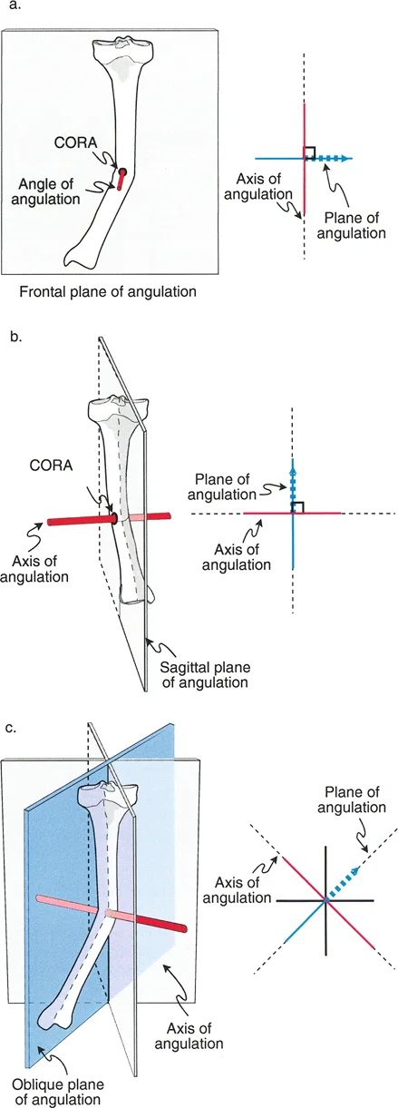
In the realm of advanced orthopedic deformity correction, mastering spatial relationships is the dividing line between a competent surgeon and a master reconstructionist. Angular deformities do not respect the neat, two-dimensional boundaries of standard radiographic views. While an angular deformity may occur in any plane, the standard reference planes in orthopedics are the two anatomic planes, specifically the coronal frontal plane and the sagittal plane. The standard reference radiographs that correspond to these planes are the anteroposterior and lateral radiographs.
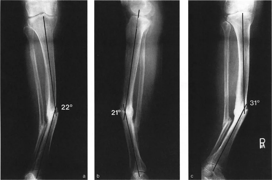
A critical conceptual pitfall for many surgeons-in-training is the misinterpretation of uniapical angular deformities. When angulation is visible on both the anteroposterior and lateral radiographs, it is frequently and incorrectly referred to as a biplanar angular deformity.
This is a fundamental biomechanical misunderstanding.
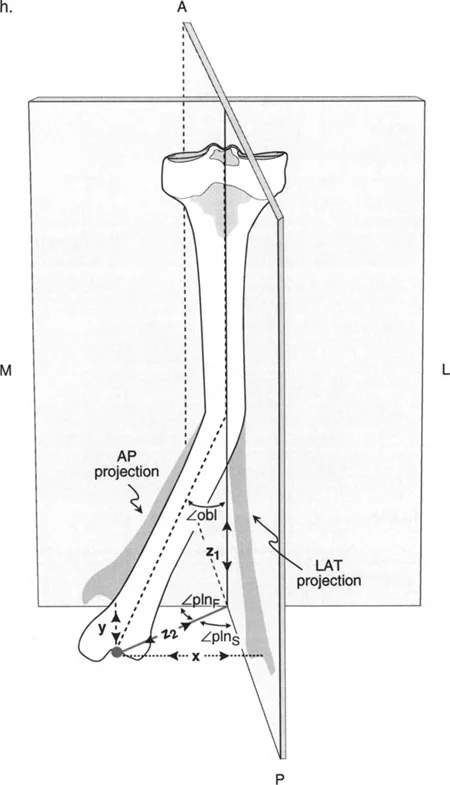
These apparent biplanar angular deformities are, in reality, uniplanar angular deformities residing in an oblique plane. This oblique plane is oriented somewhere between the true frontal and sagittal planes. Understanding this concept is the absolute bedrock of the Paley principles of deformity correction. If you treat an oblique plane deformity as two separate deformities during surgical planning, you will invariably introduce unwanted translation, secondary deformities, or mechanical axis deviation during your osteotomy and fixation.
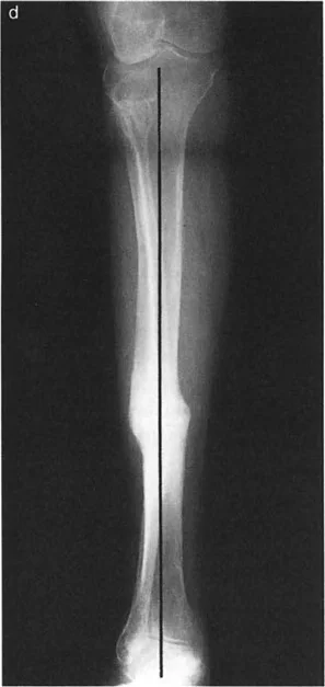
If a radiograph could be obtained exactly perpendicular to this oblique plane, the true maximum magnitude of the deformity could be measured directly. Conversely, a radiograph taken perfectly in line with the plane of angulation would show a perfectly straight bone with zero angular deformity.
Core Paley Principles of Deformity Correction
Before diving deeper into oblique plane mathematics, it is mandatory to establish the foundational Paley principles that govern all deformity corrections. Dr. Dror Paley revolutionized orthopedic surgery by standardizing how we analyze lower extremity alignment.
Mechanical Axis Deviation
The mechanical axis of the lower extremity is a line drawn from the center of the femoral head to the center of the ankle joint. In a normal limb, this line passes just medial to the center of the knee joint. Mechanical Axis Deviation occurs when this line falls outside the normal parameters, indicating malalignment. Correcting an oblique plane deformity without respecting the mechanical axis will lead to residual Mechanical Axis Deviation, premature joint degeneration, and ultimately, surgical failure.
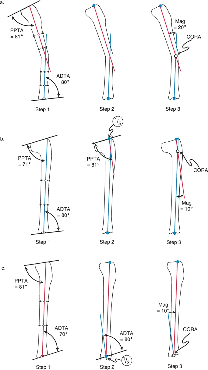
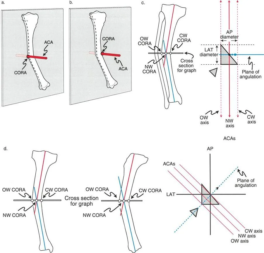
Center of Rotation of Angulation
The Center of Rotation of Angulation is the intersection point of the proximal and distal mechanical or anatomic axes of a deformed bone. Finding the true Center of Rotation of Angulation is the most critical step in preoperative planning. In an oblique plane deformity, the Center of Rotation of Angulation exists in three-dimensional space, and the osteotomy must be planned relative to this specific point to achieve perfect realignment.
Joint Orientation Angles
To determine where a deformity lies and calculate its magnitude, surgeons must rely on standardized joint orientation angles. These angles define the relationship between the anatomic or mechanical axes of the bones and the joint lines.
| Joint Orientation Angle | Abbreviation | Normal Range | Clinical Significance |
|---|---|---|---|
| Mechanical Lateral Distal Femoral Angle | mLDFA | 85 to 90 degrees | Determines distal femoral coronal alignment |
| Medial Proximal Tibial Angle | MPTA | 85 to 90 degrees | Determines proximal tibial coronal alignment |
| Posterior Proximal Tibial Angle | PPTA | 77 to 84 degrees | Determines proximal tibial sagittal alignment |
| Lateral Distal Tibial Angle | LDTA | 86 to 92 degrees | Determines distal tibial coronal alignment |
| Joint Line Convergence Angle | JLCA | 0 to 2 degrees | Assesses ligamentous laxity or intra-articular deformity |
Biomechanics of Angulation and Apical Direction
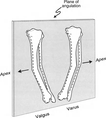
To accurately correct a bone, the surgeon must precisely define the direction in which the apex of the angulation points. The apical direction of angulation is the vector on the plane of angulation in which the apex points.
Anatomic Plane Directions
There are two possible apical directions for each standard plane of angulation.
In the sagittal plane, the apex of an anatomic plane deformity can point either anteriorly or posteriorly. Clinically, an apex anterior deformity results in procurvatum, while an apex posterior deformity results in recurvatum.
In the coronal frontal plane, the apical direction for deformities can point either medially or laterally. An apex medial deformity creates valgus, whereas an apex lateral deformity creates varus.
Oblique Plane Directions
Because an oblique plane deformity exists between the frontal and sagittal planes, its apical direction must be described by a combination of the two anatomic directions. By convention in orthopedic deformity planning, the sagittal plane direction is stated first.
This nomenclature gives us four primary quadrants for oblique plane apical directions.
- Anteromedial Deformity features Procurvatum and Valgus
- Anterolateral Deformity features Procurvatum and Varus
- Posteromedial Deformity features Recurvatum and Valgus
- Posterolateral Deformity features Recurvatum and Varus
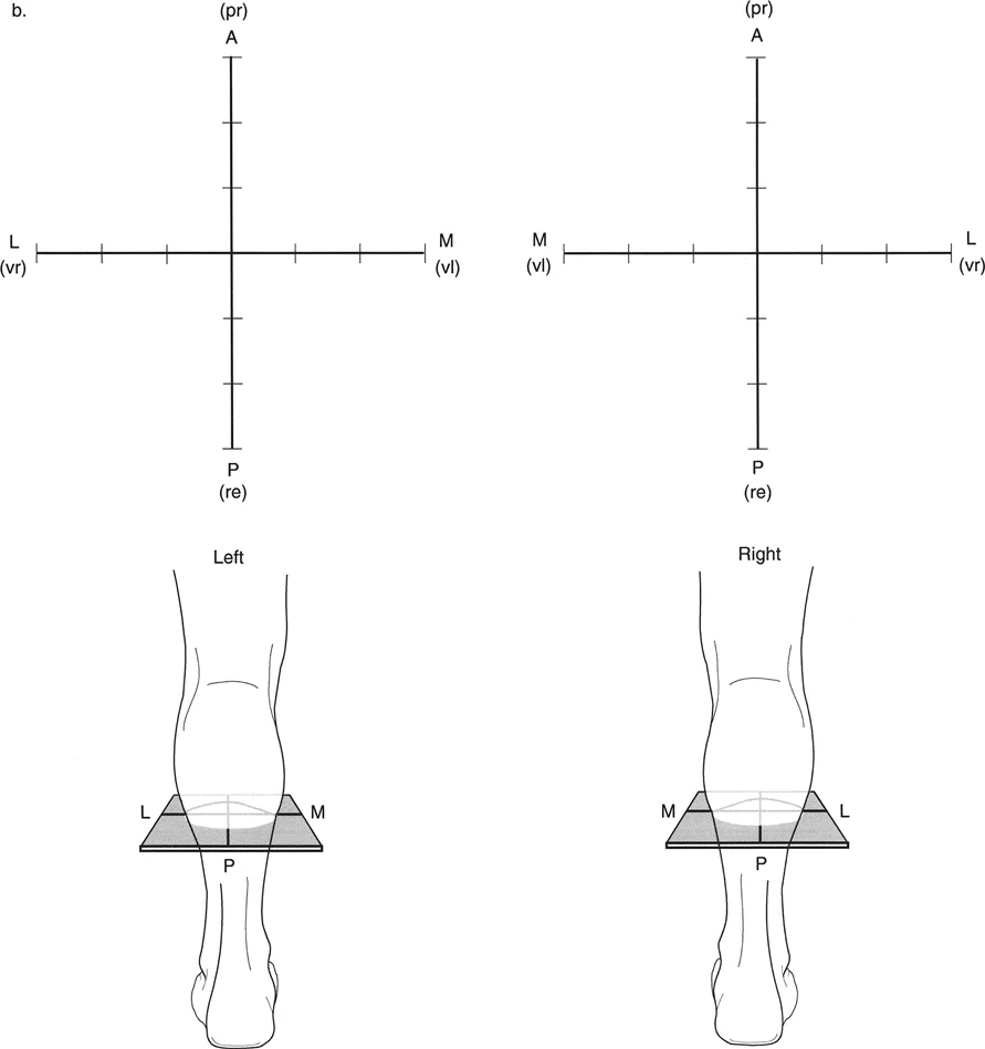
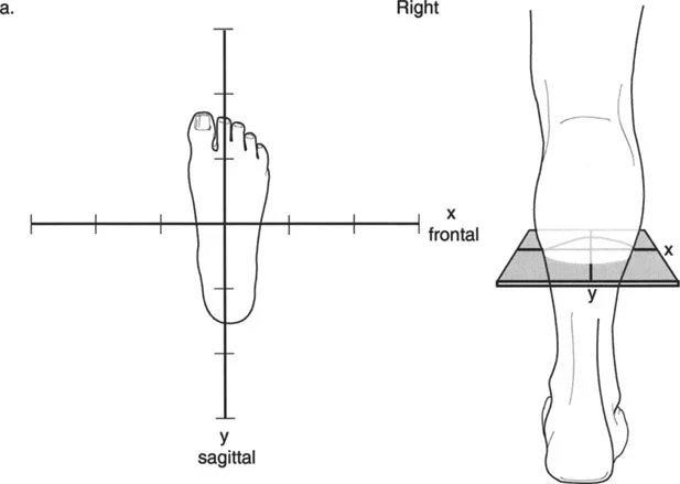
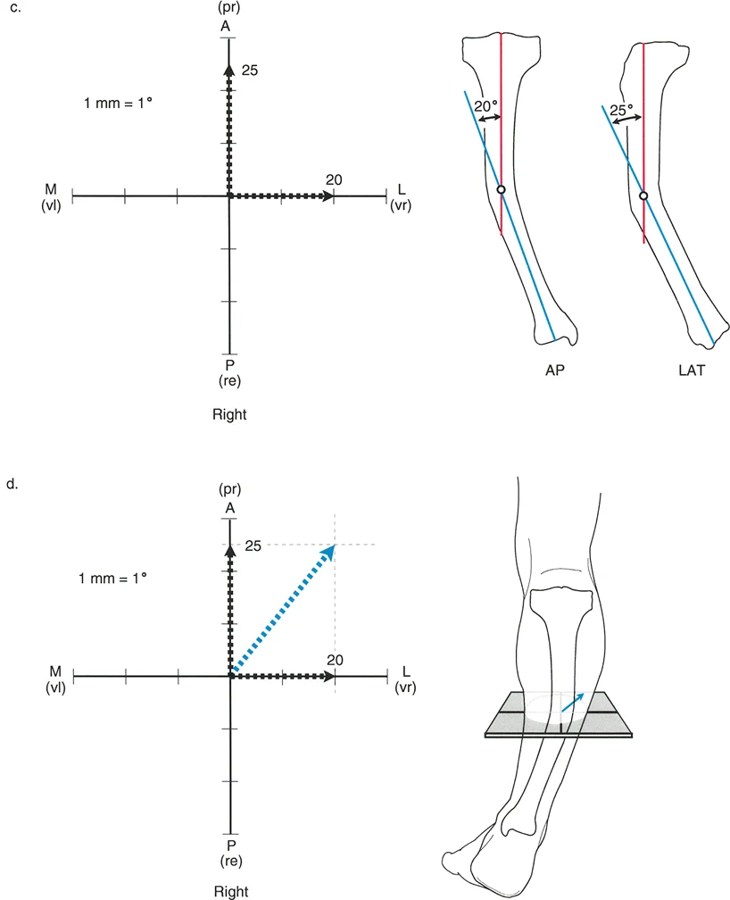
To visualize this effectively, a graph can be drawn with the apical direction labeled on the axes. This graph represents a transverse cross-section of the limb, as if the surgeon is standing at the end of the bed looking down at the patient's feet.
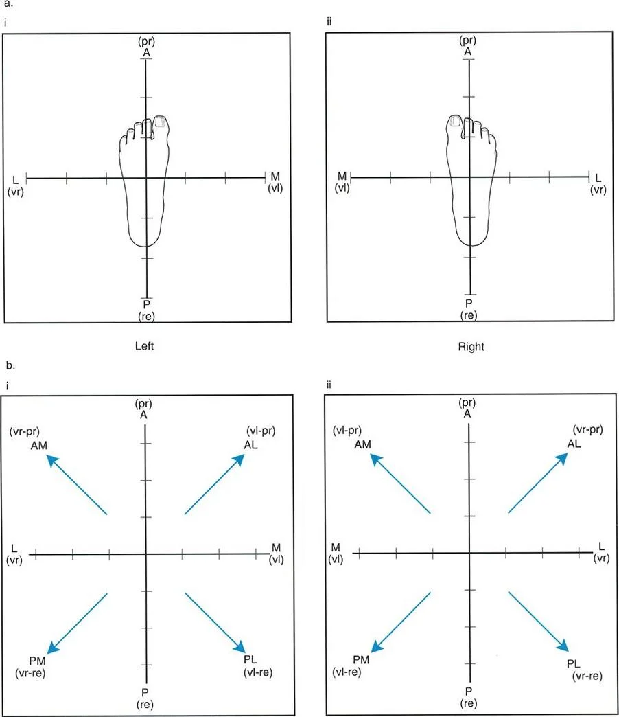
Visualizing the deformity in this transverse plane is essential for setting up external fixation frames or determining the trajectory of half-pins and wires.
Calculating True Deformity Magnitude
The magnitude of a pure anatomic plane angular deformity can be measured directly off the anteroposterior or lateral radiograph. However, in cases of oblique plane deformities, the magnitude of angulation measured on these standard films is merely a two-dimensional projection of the true deformity. The true magnitude must theoretically be measured in the oblique plane itself.
Knowing the magnitudes of angulation measured off the anteroposterior and lateral radiographs, the magnitude of the true angulation in the oblique plane can be calculated using trigonometric formulas.
Trigonometric Formulas for Oblique Planes
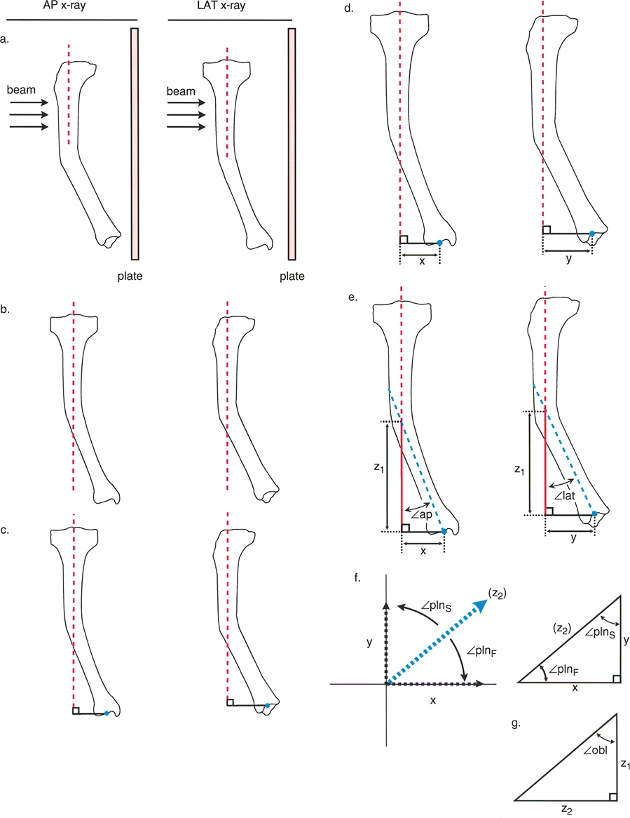
Let the variable AP represent the magnitude of angulation on the anteroposterior radiograph. Let the variable LAT represent the magnitude of angulation on the lateral radiograph.
The orientation of the true plane relative to the frontal plane is calculated using the arctangent of the tangent of LAT divided by the tangent of AP.
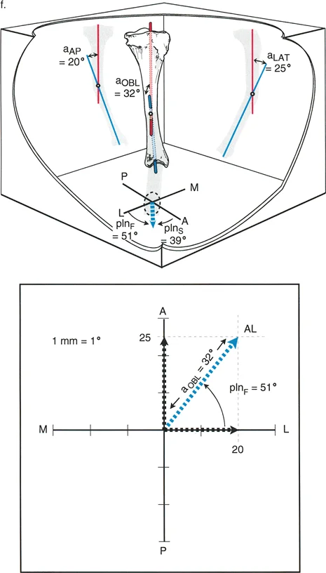
The true magnitude of angulation in the true oblique plane is calculated using the arctangent of the square root of the tangent squared of AP plus the tangent squared of LAT.
A critical rule to remember is that the true oblique magnitude is always mathematically larger than the magnitude projected in either individual reference plane. If your calculated true magnitude is smaller than your anteroposterior or lateral measurement, a calculation error has occurred.
Limitations of Nomograms and Tables
Based on these complex trigonometric calculations, Bar and Breitfuss produced a nomogram in 1989, and Ilizarov developed a comprehensive table in 1992 to determine the true values for different combinations of anteroposterior and lateral measurements.
While these historical methods eliminate the need for a scientific calculator, they require the surgeon to have the specific nomogram, table, or formulas physically on hand in the busy clinic or operating room. Because these reference materials are frequently misplaced or unavailable, oblique plane analysis is often skipped by surgeons. This omission leads directly to suboptimal corrections, residual Mechanical Axis Deviation, and poor joint orientation angles.
To solve this widespread clinical problem, Dr. Dror Paley developed a highly practical, user-friendly graphical method that requires nothing more than a piece of paper, a pencil, and a protractor.
Paley Graphic Method for Oblique Deformities
To understand the deformity preoperatively and execute a perfect osteotomy at the Center of Rotation of Angulation, it is essential to determine the exact plane, direction, and magnitude of the oblique plane angulation. The Paley graphic method allows surgeons to bypass complex trigonometry and rapidly determine the true deformity parameters.
Executing the Graphic Method
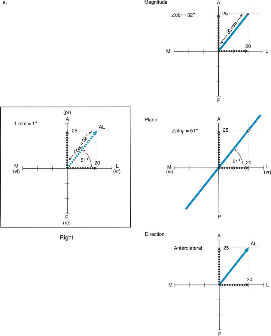
The Paley graphic method utilizes a simple Cartesian coordinate system to plot the deformity.
First, draw a horizontal X-axis to represent the coronal plane and a vertical Y-axis to represent the sagittal plane. The intersection of these axes represents the neutral mechanical axis of the bone.
Next, plot the magnitude of the coronal plane deformity on the X-axis. If the deformity is valgus, plot it on the positive X-axis. If it is varus, plot it on the negative X-axis.
Then, plot the magnitude of the sagittal plane deformity on the Y-axis. If the deformity is procurvatum, plot it on the positive Y-axis. If it is recurvatum, plot it on the negative Y-axis.
Draw perpendicular lines from these two plotted points to create a rectangle. Draw a diagonal line from the origin to the opposite corner of the rectangle.
This diagonal line represents the true oblique plane deformity. The length of this diagonal line represents the true magnitude of the deformity. The angle of this diagonal line relative to the X-axis represents the orientation of the oblique plane.
Clinical Pearls for the Graphic Method
- Scale Matters: Ensure you use a consistent scale when plotting your measurements. For example, let one millimeter on your ruler equal one degree of deformity.
- Quadrant Check: Always verify that your resulting diagonal line falls into the correct anatomical quadrant. An anteromedial deformity must fall into the upper right quadrant of your graph.
- Hinge Placement: The axis of correction, or the hinge in an external fixator, must be placed exactly perpendicular to the diagonal line representing the true oblique plane.
Paley Osteotomy Rules
Once the true magnitude and plane of the oblique deformity are calculated, the surgeon must plan the osteotomy. Dr. Paley established three fundamental osteotomy rules that dictate how a bone will behave when cut and realigned. Mastering these rules is non-negotiable for orthopedic reconstructionists.
Osteotomy Rule One
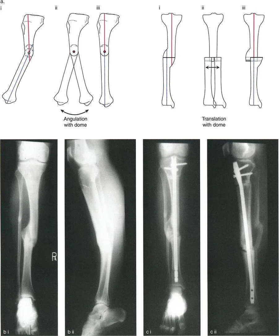
When the osteotomy and the axis of correction hinge are both placed at the Center of Rotation of Angulation, the bone will undergo pure angulation. The proximal and distal mechanical axes will align perfectly without any translation. This is the ideal scenario for correcting an oblique plane deformity, as it restores the mechanical axis seamlessly and creates a highly stable bony contact area.
Osteotomy Rule Two
When the axis of correction hinge is placed at the Center of Rotation of Angulation, but the osteotomy is performed at a different level, the bone will undergo angulation and translation. While the proximal and distal mechanical axes will ultimately align, the translation at the osteotomy site can lead to poor bone contact, delayed union, or prominent bony contours that irritate soft tissues. This rule is often utilized intentionally when the Center of Rotation of Angulation is located too close to a joint line to allow for adequate fixation, forcing the surgeon to make the cut further down the diaphysis.
Osteotomy Rule Three
When the osteotomy and the axis of correction hinge are both placed outside the Center of Rotation of Angulation, the bone will undergo angulation, but the proximal and distal mechanical axes will not align. This results in a new translation deformity and significant Mechanical Axis Deviation. Rule three is a surgical error in the context of pure angular deformity correction and must be avoided, as it will inevitably lead to joint malalignment and altered limb biomechanics.
Step by Step Preoperative Planning Workflow
Successfully managing an oblique plane deformity requires a disciplined, reproducible preoperative planning workflow. Skipping steps in this process is the primary cause of intraoperative confusion and postoperative malalignment.
Step One Radiographic Evaluation
Obtain high-quality, full-length, weight-bearing anteroposterior and lateral radiographs of the entire lower extremity. The patella must be facing perfectly forward on the anteroposterior view to ensure accurate coronal plane assessment. Calibrate the images using a standard radiopaque marker to allow for accurate measurement of leg length discrepancies, which frequently accompany oblique plane deformities.
Step Two Axis Determination
Draw the mechanical axis of the normal limb to establish your baseline. On the deformed limb, draw the proximal mechanical axis and the distal mechanical axis. Extend these lines until they intersect.
Step Three Identifying the CORA
The intersection point of the proximal and distal mechanical axes is the Center of Rotation of Angulation. Mark this point clearly on both the anteroposterior and lateral radiographs. Note the relationship of the Center of Rotation of Angulation to the joint lines and the diaphysis.
Step Four Deformity Measurement
Measure the angle between the proximal and distal axes on the anteroposterior radiograph. Repeat this process on the lateral radiograph. You now have your coronal and sagittal plane magnitudes.
Step Five Applying the Graphic Method
Utilize the Paley graphic method described earlier to plot your anteroposterior and lateral measurements. Draw the rectangle, find the diagonal, and measure the true oblique plane magnitude and orientation. This step transforms your two-dimensional data into a actionable three-dimensional surgical plan.
Step Six Osteotomy and Fixation Planning
Select your osteotomy site based on the Paley Osteotomy Rules. If possible, plan your cut exactly at the Center of Rotation of Angulation to satisfy Rule One. Decide on your fixation method, whether it be a circular external fixator, an intramedullary nail, or a specialized plate.
Surgical Execution and Fixation Strategies
The physical execution of the preoperative plan requires meticulous attention to detail. The choice of fixation depends heavily on the magnitude of the deformity, the quality of the soft tissues, and the presence of any accompanying leg length discrepancy.
Circular External Fixation
Circular frames, such as the Ilizarov apparatus or the Taylor Spatial Frame, are the gold standard for complex oblique plane deformities. The Taylor Spatial Frame utilizes a specialized hexapod computer program that allows for simultaneous correction of angulation, translation, and length in all six degrees of freedom.
When using a circular frame, the rings must be mounted orthogonally to the proximal and distal bone segments. The virtual hinge of the computer program is placed exactly at the calculated Center of Rotation of Angulation.
Intramedullary Nailing
Advancements in intramedullary nailing techniques, specifically the use of blocking screws or Poller screws, have made acute correction of oblique plane deformities highly effective. Blocking screws are placed strategically to narrow the medullary canal and guide the path of the nail, forcing the bone segments into the corrected alignment.
When planning for an intramedullary nail, the surgeon must calculate the exact wedge of bone to be removed or the exact opening wedge to be created at the osteotomy site. The true oblique plane magnitude dictates the size of this wedge.
Plate Osteosynthesis
For metaphyseal oblique plane deformities, opening wedge or closing wedge osteotomies stabilized with locking plates provide rigid internal fixation. The hinge of the osteotomy must be oriented perpendicular to the true oblique plane calculated via the Paley graphic method. If the hinge is not oriented correctly, the surgeon will inadvertently introduce a secondary deformity as the wedge is opened or closed.
Postoperative Management and Rehabilitation
The success of an oblique plane deformity correction extends far beyond the operating room. Postoperative management must be tightly controlled to ensure bone healing and functional recovery.
Weight Bearing Protocols
Weight-bearing protocols vary based on the chosen fixation method. Circular external fixators generally allow for immediate weight-bearing as tolerated, which promotes osteogenesis through micromotion. Intramedullary nails and plates typically require a period of protected weight-bearing until radiographic evidence of bridging callus is observed.
Radiographic Monitoring
Frequent radiographic monitoring is essential. Postoperative full-length, weight-bearing radiographs should be obtained to verify the restoration of the mechanical axis and the normalization of the joint orientation angles. If a hexapod external fixator is utilized, residual deformities can be corrected postoperatively by adjusting the computer program, highlighting the immense power and flexibility of this technique.
Physical Therapy Focus
Physical therapy must focus on early joint mobilization to prevent stiffness, particularly in the knee and ankle. Muscle strengthening and gait retraining are critical components of the rehabilitation process, ensuring the patient can fully utilize their newly aligned, biomechanically optimized lower extremity.
!!! info "Academic Resource & Medical Review"
This academic resource was prepared and medically reviewed by Prof. Dr. Mohammed Hutaif, Consultant Orthopedic & Spine Surgeon. It is formulated specifically for medical students, orthopedic residents, and surgeons preparing for high-stakes board examinations (AAOS, FRCS Tr & Orth, Arab Board).
!!! warning "Disclaimer"
The surgical techniques, classifications, and clinical guidelines presented herein are for educational and academic review purposes only. They are not intended to replace institutional protocols or independent clinical judgment.
You Might Also Like