Mastering Frontal Plane Realignment: Paley Osteotomy & Deformity Correction
Key Takeaway
Frontal plane realignment, guided by the Paley method, applies geometric principles to correct lower extremity deformities. It involves precise analysis of mechanical axes, joint orientation angles, and identifying the Center of Rotation of Angulation (CORA) to plan predictable osteotomies, restoring optimal biomechanics and joint longevity.
Introduction to Frontal Plane Realignment and Osteotomy Concepts
In the realm of orthopedic deformity correction, achieving precise anatomical and mechanical alignment is the ultimate goal. For decades, the correction of lower extremity deformities was treated as more of an art than a science. Surgeons relied heavily on intraoperative visual estimation, often resulting in unpredictable outcomes, secondary joint degeneration, and residual malalignment. This paradigm shifted dramatically with the introduction of Dr. Dror Paley systematic approach to deformity analysis and correction. By applying rigorous geometric and mathematical principles to the human skeleton, the Paley method transformed orthopedic reconstruction into a highly predictable science.
This comprehensive masterclass delves deep into Frontal Plane Realignment and the foundational Osteotomy Concepts that govern modern orthopedic surgery. Whether you are addressing a post-traumatic tibial malunion, congenital bowing, Blount disease, or degenerative varus and valgus deformities, mastering the geometric principles of the Center of Rotation of Angulation, the Angulation Correction Axis, and Mechanical Axis Deviation is strictly non-negotiable for the orthopedic surgeon-in-training.
By transitioning away from intuitive corrections and moving toward rigorous geometric preoperative planning, surgeons can predictably restore normal joint orientation, optimize load-bearing biomechanics, and ensure the longevity of the patient native joints. This guide will break down the fundamental rules of osteotomies, compare opening wedge, closing wedge, and dome techniques, and provide a comprehensive step-by-step clinical blueprint for executing a flawless frontal plane realignment.
The Biomechanical Lexicon of Deformity Correction
Before diving into surgical techniques, osteotomy sequences, and fixation strategies, the orthopedic surgeon must become completely fluent in the biomechanical language of lower extremity alignment. The frontal plane, also known as the coronal plane, is the primary plane of weight-bearing load distribution. Any deviation in this plane drastically alters the contact pressures across the articular cartilage of the knee and ankle joints, accelerating localized osteoarthritis.
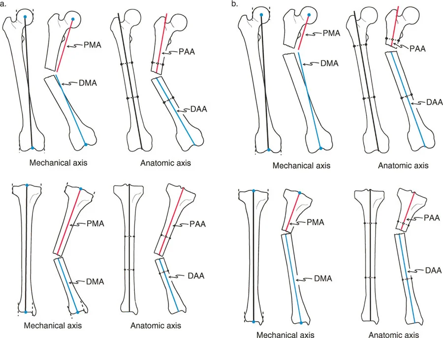
Mechanical and Anatomic Axes Defined
Understanding the difference between mechanical and anatomic axes is the first step in deformity analysis. These lines form the basis of all subsequent angular measurements.
- Mechanical Axis of the Lower Extremity
Often abbreviated as MALE, this is a straight line drawn from the exact center of the femoral head to the center of the ankle joint at the tibial plafond. In a normally aligned, healthy lower limb, this weight-bearing line passes exactly through the center of the knee joint, or slightly medial to the tibial spines. - Anatomic Axis of the Femur
This is a line drawn through the mid-diaphysis of the femur. Because the femur has a natural lateral bow and a distinct neck-shaft angle, the anatomic axis of the femur is not a straight line from the hip to the knee. Instead, it sits at an angle, typically 7 degrees with a standard deviation of 2 degrees, to the femoral mechanical axis. Failing to account for this 7-degree difference is a classic pitfall in intramedullary nailing of distal femur fractures, often leading to iatrogenic valgus malunion. - Anatomic Axis of the Tibia
Unlike the femur, the anatomic axis of the tibia, drawn through its mid-diaphysis, is essentially parallel to its mechanical axis. In most clinical scenarios, the tibial anatomic and mechanical axes can be considered superimposed and interchangeable for planning purposes.
Calculating Mechanical Axis Deviation
Mechanical Axis Deviation is the primary metric used to quantify the overall magnitude of a frontal plane deformity. It is defined as the perpendicular distance measured in millimeters from the exact center of the knee joint to the mechanical axis line of the lower extremity.
- Medial Mechanical Axis Deviation
When the mechanical axis passes medial to the center of the knee, the limb is in varus. This medial shift exponentially increases the compressive forces on the medial compartment of the knee, predisposing the patient to medial meniscus tears and medial compartment osteoarthritis. - Lateral Mechanical Axis Deviation
When the mechanical axis passes lateral to the center of the knee, the limb is in valgus. This lateral shift overloads the lateral compartment, stretching the medial collateral ligament and compressing the lateral meniscus and articular cartilage.
The Malalignment Test is the initial diagnostic step. If a long-leg standing radiograph reveals a Mechanical Axis Deviation outside the normal range of 0 to 8 millimeters medial to the center of the knee, a structural deformity exists, and further joint orientation analysis is required to pinpoint its exact location.
Joint Orientation Angles in Deformity Analysis
To determine exactly where a deformity originates, whether it is in the femur, the tibia, or within the knee joint itself, the surgeon must measure the joint orientation angles in the frontal plane. These angles represent the relationship between the mechanical or anatomic axes of the bone and the joint lines of the knee and ankle.
Standard Joint Orientation Values
Memorizing the normal values for joint orientation angles is critical for rapid and accurate radiographic analysis. The following angles are measured on a standardized, weight-bearing, long-leg anteroposterior radiograph.
| Angle Designation | Full Name | Normal Value | Clinical Significance |
|---|---|---|---|
| mLDFA | Mechanical Lateral Distal Femoral Angle | 87° (Range 85°-90°) | Evaluates distal femoral varus/valgus. An mLDFA > 90° indicates femoral varus. An mLDFA < 85° indicates femoral valgus. |
| MPTA | Medial Proximal Tibial Angle | 87° (Range 85°-90°) | Evaluates proximal tibial varus/valgus. An MPTA < 85° indicates tibial varus. An MPTA > 90° indicates tibial valgus. |
| LDTA | Lateral Distal Tibial Angle | 89° (Range 86°-92°) | Evaluates distal tibial varus/valgus at the ankle joint. Crucial for supramalleolar osteotomy planning. |
| mLPFA | Mechanical Lateral Proximal Femoral Angle | 90° (Range 85°-95°) | Evaluates the proximal femur and hip joint orientation. |
Joint Line Convergence Angle and Soft Tissue Laxity
While mLDFA and MPTA evaluate the bony anatomy, the Joint Line Convergence Angle evaluates the intra-articular space and soft tissue envelope. The Joint Line Convergence Angle is the angle formed between the distal femoral articular line and the proximal tibial articular line.
In a normal knee, these lines are nearly parallel, resulting in a Joint Line Convergence Angle of 0 to 2 degrees. If this angle is significantly increased, it indicates intra-articular deformity, asymmetrical cartilage wear, or collateral ligament laxity. For example, a patient with severe medial compartment osteoarthritis may have a varus deformity driven entirely by cartilage loss and lateral ligament stretching, rather than a true bony deformity of the femur or tibia. Recognizing an abnormal Joint Line Convergence Angle prevents the surgeon from performing an unnecessary bony osteotomy for a purely soft-tissue or intra-articular problem.
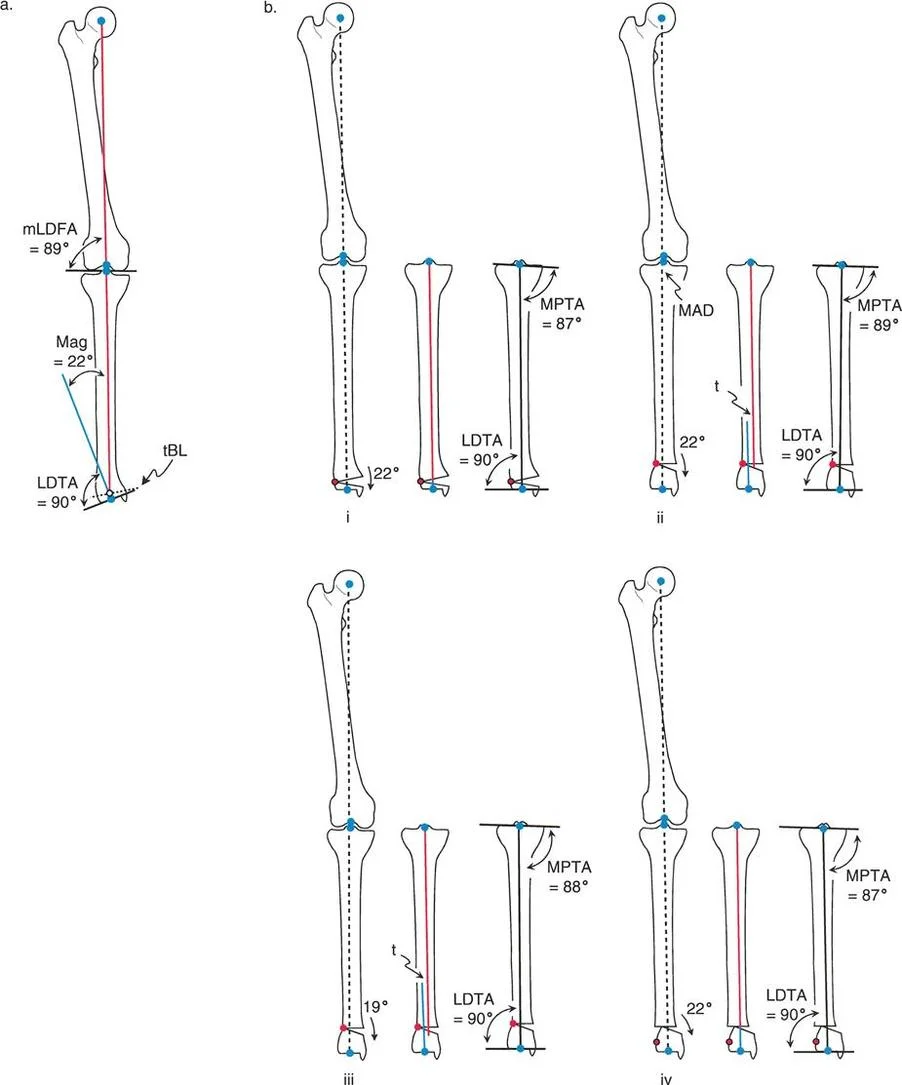
Center of Rotation of Angulation and Angulation Correction Axis
The genius of the Paley method lies in its geometric abstraction of deformed bones. By reducing complex three-dimensional malunions into intersecting lines and hinge points, surgeons can plan corrections with mathematical certainty. The two most critical concepts in this geometric framework are the Center of Rotation of Angulation and the Angulation Correction Axis.
Finding the Center of Rotation of Angulation
The Center of Rotation of Angulation is the specific intersection point of the proximal and distal axes of a deformed bone. To find it, the surgeon draws the mechanical or anatomic axis of the proximal bone segment, and then draws the mechanical or anatomic axis of the distal bone segment. The exact point where these two lines intersect on the radiograph is the Center of Rotation of Angulation.
A single bone may have one uniapical deformity with a single Center of Rotation of Angulation, or it may have a complex, sweeping multiapical deformity with multiple intersecting centers. Accurately identifying this point is the absolute prerequisite for planning the level and type of osteotomy.
The Role of the Angulation Correction Axis
While the Center of Rotation of Angulation is a geometric point on a radiograph, the Angulation Correction Axis is a physical, mechanical reality in the operating room. The Angulation Correction Axis is the actual physical hinge point around which the surgeon rotates the bone segments during the osteotomy execution.
If the surgeon is using a hinged external fixator, such as an Ilizarov frame or a Taylor Spatial Frame, the mechanical hinge of the frame serves as the Angulation Correction Axis. If the surgeon is performing an open wedge high tibial osteotomy with a plate, the intact lateral cortical hinge of the tibia serves as the Angulation Correction Axis. The spatial relationship between the geometric Center of Rotation of Angulation and the physical Angulation Correction Axis dictates the final alignment of the limb and forms the basis of the Three Paley Rules of Osteotomy.
The Three Paley Rules of Osteotomy
Understanding exactly how an osteotomy behaves requires mastering the three fundamental rules established by Dr. Dror Paley. These rules dictate whether a surgical correction will result in pure angulation, angulation with intentional translation, or the disastrous introduction of a new, iatrogenic deformity.
Rule One Pure Angular Correction
The first rule describes the geometrically perfect realignment. When the osteotomy cut passes exactly through the Center of Rotation of Angulation, and the physical hinge point is placed exactly on the Center of Rotation of Angulation, the result is pure angular correction.
In this scenario, the proximal and distal axes will realign perfectly, becoming entirely collinear without any translation or displacement of the bone ends. This restores the anatomic axis alignment and normalizes both knee and ankle joint orientation simultaneously. Clinically, this is often achievable in metaphyseal deformities where the Center of Rotation of Angulation lies close to the joint line, allowing the surgeon to make the bone cut directly at the apex of the deformity.
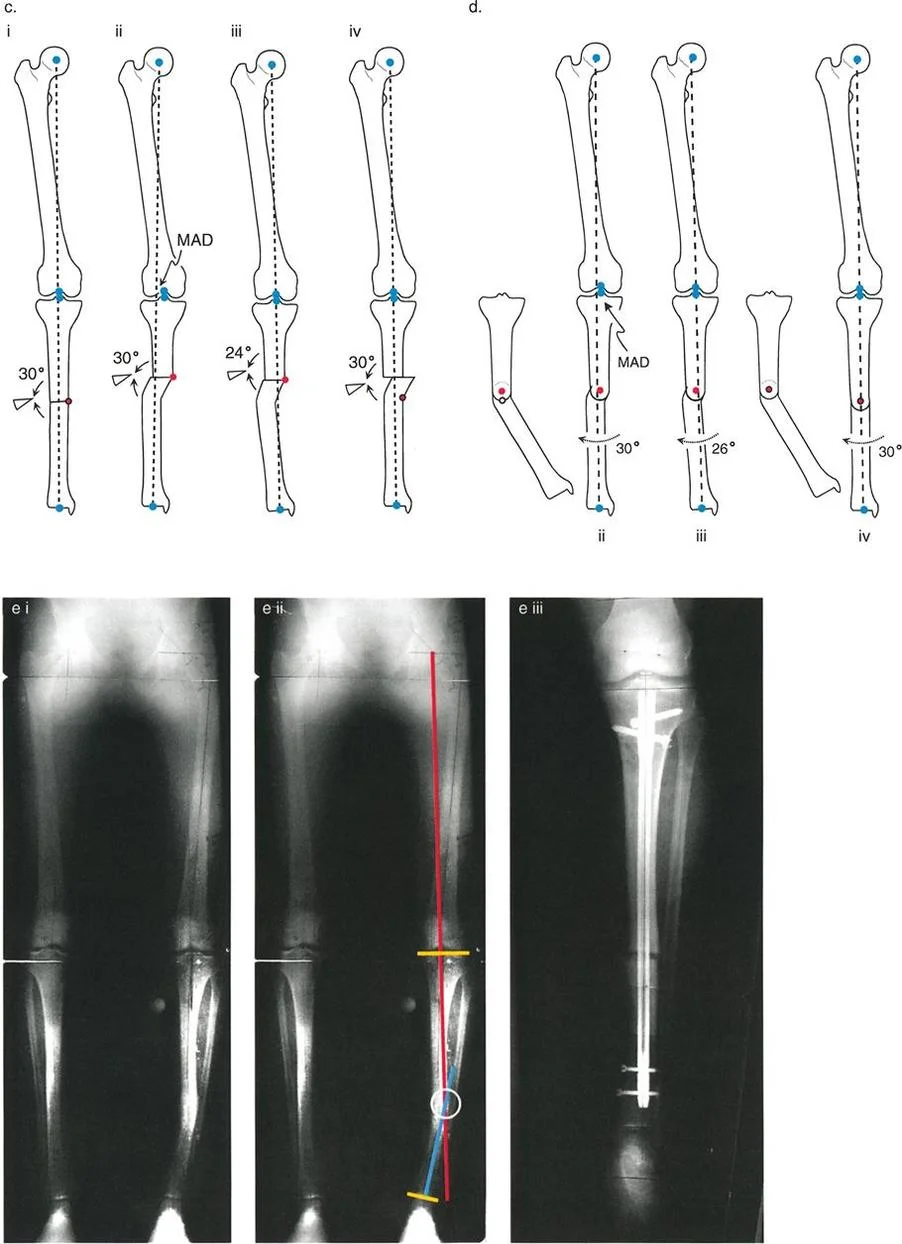
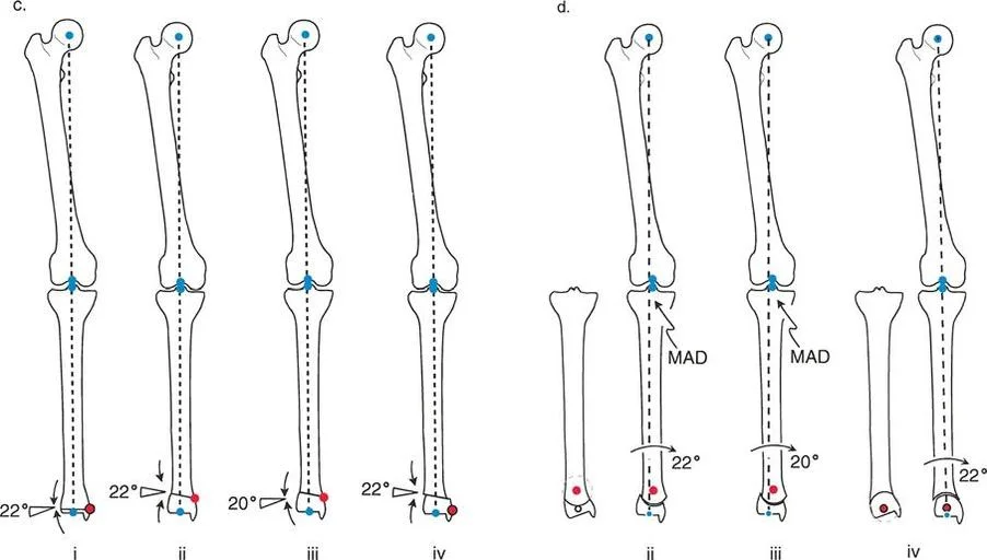
Rule Two Angulation with Intentional Translation
The second rule addresses the clinical reality that we cannot always cut the bone exactly at the apex of the deformity. Often, the Center of Rotation of Angulation is located in the diaphysis, where cortical bone heals slowly, or near compromised soft tissues.
Rule Two states that when the osteotomy line is made at a different level than the Center of Rotation of Angulation, but the physical hinge point is still maintained exactly on the Center of Rotation of Angulation, the mechanical axes will realign perfectly. However, the bone ends at the osteotomy site will translate relative to one another.
This translation is a necessary, unavoidable geometric consequence of correcting around a remote hinge. It is biomechanically sound and restores the mechanical axis perfectly, even though it creates a visible step-off or zigzag deformity in the diaphysis on the radiograph. Over time, Wolff Law dictates that this translated bone will remodel. Surgeons frequently utilize Rule Two when correcting diaphyseal bowing by performing the osteotomy in the well-vascularized metaphysis while hinging the correction around the diaphyseal apex using an external fixator.
Rule Three Induced Translation Deformity
The third rule represents the classic pitfall of intuitive, non-planned deformity correction. Rule Three states that when the osteotomy line is made at a different level than the Center of Rotation of Angulation, and the physical hinge point is placed at the osteotomy site rather than on the true apex, angular correction is achieved, but a secondary translation deformity is created.
In this failure scenario, the proximal and distal axes will become parallel to each other, but they will not be collinear. This introduces a brand new Mechanical Axis Deviation. This is the exact error that occurs when a surgeon simply wedges out a deformity at the site of maximum bowing without calculating the true intersecting axes. The limb may look straighter to the naked eye, but the knee or ankle joint remains mechanically overloaded due to the induced translation.
Deformity Planning and Osteotomy Sequences
Once the axes are drawn, the apex is identified, and the appropriate rule is selected, the surgeon must choose the specific geometric shape of the bone cut. Let us analyze the specific osteotomy geometries used in frontal plane realignment, focusing on Opening Wedge, Closing Wedge, and Dome osteotomies.
The Opening Wedge Sequence
The opening wedge osteotomy is a foundational technique that not only corrects angulation but also adds length to the bone. This makes it highly beneficial in cases where a frontal plane deformity is accompanied by a limb length discrepancy.
In an opening wedge sequence, a single transverse or oblique cut is made, leaving a cortical hinge intact on the convex side of the deformity. The bone is then slowly wedged open on the concave side until the desired angular correction is achieved.
Advantages of Opening Wedge:
* Predictable correction with a single bone cut.
* Adds overall length to the limb, addressing shortening.
* Does not require technically demanding wedge resection calculations.
Disadvantages of Opening Wedge:
* Creates a bony void that may require structural allograft or autograft, depending on the gap size.
* Increases tension on the surrounding soft tissues, potentially stretching nerves or vessels.
* Can alter patellofemoral mechanics by changing the tibial slope if not executed perfectly.
The Closing Wedge Sequence
The closing wedge osteotomy involves removing a precise, pre-calculated wedge of bone from the convex side of the deformity and closing the gap, hinging on the concave cortex.
Advantages of Closing Wedge:
* Provides immediate, broad bony contact, leading to rapid primary bone healing.
* Inherently stable, allowing for earlier weight-bearing protocols.
* Relaxes the soft tissues on the convex side, reducing the risk of nerve stretch injuries.
Disadvantages of Closing Wedge:
* Shortens the overall length of the limb, which is detrimental if the patient already has a leg length discrepancy.
* Technically demanding, as the surgeon must cut two perfectly intersecting planes of bone. Over-resecting or under-resecting the wedge leads to under-correction or over-correction.
The Dome Osteotomy Sequence
The dome osteotomy, or focal dome osteotomy, utilizes a cylindrical or spherical bone cut. The bone segments are rotated along the arc of the dome to achieve correction.
Advantages of Dome Osteotomy:
* Allows for massive angular corrections without altering the length of the limb.
* Maintains excellent bone-to-bone contact regardless of the degree of rotation, facilitating strong healing without bone graft.
* Highly adjustable intraoperatively before final fixation is applied.
Disadvantages of Dome Osteotomy:
* Highly technically demanding, requiring specialized curved saw blades or a series of precise drill holes to create the dome shape.
* Requires extensive soft tissue stripping to access the entire circumference of the bone for the curved cut.
Step by Step Preoperative Planning for Frontal Plane Deformity
Executing a flawless frontal plane realignment requires meticulous preoperative planning. The Reverse Planning Method is the gold standard for translating radiographic measurements into surgical action.
Malalignment Test and Deformity Localization
- Obtain Proper Imaging: Acquire a standing, weight-bearing, long-leg anteroposterior radiograph with the patellae facing strictly forward.
- Draw the Mechanical Axis of the Lower Extremity: Draw a line from the center of the femoral head to the center of the ankle plafond.
- Measure Mechanical Axis Deviation: Measure the distance from the center of the knee to the mechanical axis line to quantify the varus or valgus deviation.
- Measure Joint Orientation Angles: Calculate the mLDFA, MPTA, and LDTA to isolate whether the deformity is femoral, tibial, or combined.
Osteotomy Design and Fixation Strategy
- Draw the Proximal and Distal Axes: Based on normal joint orientation angles, draw the ideal mechanical axis for the proximal segment and the ideal mechanical axis for the distal segment.
- Locate the Center of Rotation of Angulation: Mark the exact intersection of these two drawn axes.
- Select the Osteotomy Level and Rule: Decide where the bone cut will be made based on soft tissue quality and bone healing potential. Apply Paley Rule One, Two, or Three to predict the geometric outcome.
- Determine the Hinge Point: Choose the Angulation Correction Axis. If using a plate, plan the location of the intact cortical hinge. If using an external fixator, plan the placement of the mechanical frame hinge.
- Select Fixation: Choose between locking plates, intramedullary nails, or circular external fixation based on the complexity of the deformity, the need for gradual vs. acute correction, and the patient soft tissue envelope.
Clinical Pearls for Frontal Plane Realignment
To elevate your surgical outcomes from acceptable to exceptional, consider these high-yield clinical pearls gathered from master deformity surgeons.
- Respect the Fibula: In any significant tibial correction, the intact fibula acts as a lateral tether. Failing to perform a fibular osteotomy or release the proximal tibiofibular joint will restrict your correction and force the tibia into an unwanted valgus or procurvatum deformity.
- Beware the Peroneal Nerve: Large valgus corrections of the proximal tibia (correcting a severe varus deformity) place immense stretch on the common peroneal nerve. Consider a prophylactic peroneal nerve decompression at the fibular neck for acute corrections exceeding 10 to 12 degrees.
- Account for the Saw Blade: A standard oscillating saw blade removes 1 to 1.5 millimeters of bone. In a closing wedge osteotomy, failing to account for the thickness of the blade on both cuts will result in a wedge that is 2 to 3 millimeters larger than planned, leading to over-correction.
- Protect the Hinge: The intact cortical hinge is the most critical element of an opening or closing wedge osteotomy. If the hinge fractures during the opening or closing process, the osteotomy becomes violently unstable, and control over the Angulation Correction Axis is lost. Always drill a stress-relieving hole at the apex of the planned wedge to dissipate forces and protect the hinge.
- Manage the Sagittal Plane: Frontal plane deformities rarely exist in isolation. Always evaluate the sagittal plane for concurrent procurvatum or recurvatum. Altering the frontal plane with a wedge osteotomy can inadvertently change the posterior tibial slope, drastically affecting knee kinematics and cruciate ligament tension.
Conclusion and Future Directions in Deformity Correction
Mastering frontal plane realignment is a defining milestone in the career of an orthopedic surgeon. The transition from intuitive, visual surgery to precise, mathematically driven osteotomy planning has revolutionized patient outcomes, allowing for the predictable restoration of limb alignment and joint preservation.
By internalizing the biomechanical lexicon, rigorously applying the concepts of the Center of Rotation of Angulation and the Angulation Correction Axis, and strictly adhering to the Three Paley Rules of Osteotomy, surgeons can tackle even the most complex lower extremity deformities with absolute confidence. As technology advances, the integration of three-dimensional computed tomography planning, patient-specific cutting guides, and robotic-assisted osteotomy execution will continue to refine these foundational principles. However, the underlying geometric truths established by Dr. Dror Paley will remain the immutable bedrock of orthopedic deformity correction for generations to come.
!!! info "Academic Resource & Medical Review"
This academic resource was prepared and medically reviewed by Prof. Dr. Mohammed Hutaif, Consultant Orthopedic & Spine Surgeon. It is formulated specifically for medical students, orthopedic residents, and surgeons preparing for high-stakes board examinations (AAOS, FRCS Tr & Orth, Arab Board).
!!! warning "Disclaimer"
The surgical techniques, classifications, and clinical guidelines presented herein are for educational and academic review purposes only. They are not intended to replace institutional protocols or independent clinical judgment.
You Might Also Like