Mastering the Posterior C1-2 Vertebral Space Surgical Approach
Key Takeaway
This article provides essential research regarding Mastering the Posterior C1-2 Vertebral Space Surgical Approach. The posterior approach to the C1-2 c vertebral space is a surgical technique for the atlas (C1) and axis (C2) vertebrae. This approach is utilized for spinal fusion, decompression laminectomy, treating tumors, and stabilizing C1/C2 fractures. It involves a midline incision from the external occipital protuberance, with careful dissection of paracervical muscles to access the posterior elements.
Mastering the Posterior C1-2 Vertebral Space Surgical Approach
Introduction & Epidemiology
The posterior approach to the atlantoaxial complex, comprising C1 (atlas) and C2 (axis), represents a foundational technique in spinal surgery, addressing a spectrum of pathologies unique to this highly specialized region of the cervical spine. Unlike the subaxial cervical spine, C1 and C2 possess distinct anatomical and biomechanical characteristics critical for head movement and spinal cord protection. The atlantoaxial joint, responsible for approximately 50% of cervical rotation, lacks typical intervertebral discs, relying instead on a robust ligamentous complex for stability. Pathologies in this region, whether traumatic, degenerative, congenital, or neoplastic, often result in instability, neurological compromise, or intractable pain, necessitating surgical intervention.
The incidence of atlantoaxial instability varies based on etiology. Traumatic injuries, particularly odontoid fractures (Type II and III), C1 burst fractures (Jefferson fractures), and atlantoaxial rotatory subluxations, are common presentations. Non-traumatic conditions include rheumatoid arthritis with pannus formation and ligamentous laxity, os odontoideum, Down syndrome-associated instability, Klippel-Feil syndrome, and various neoplastic processes. Historically, wiring techniques dominated C1-C2 fixation; however, advancements in instrumentation, notably the C1 lateral mass and C2 pedicle/pars screw constructs (Goel-Harms technique), have revolutionized stability and fusion rates, making this approach a cornerstone of complex cervical spine surgery.
Surgical Anatomy & Biomechanics
A comprehensive understanding of the intricate anatomy and biomechanics of the C1-C2 complex is paramount for safe and effective surgical intervention.
C1 (Atlas)
C1 is a ring-shaped vertebra lacking a vertebral body and spinous process. It consists of anterior and posterior arches, and two lateral masses. The posterior arch provides attachment for the posterior atlanto-occipital membrane and several small muscles. Its superior surface has a groove for the vertebral artery. The lateral masses articulate superiorly with the occipital condyles and inferiorly with the superior articular facets of C2. They contain critical anatomical landmarks for screw placement.
C2 (Axis)
C2 is characterized by the odontoid process (dens) , which projects superiorly from its body and articulates with the anterior arch of C1, forming the atlantoaxial joint. The spinous process of C2 is the largest bifid spinous process in the cervical spine, serving as a key surgical landmark and attachment point for the nuchal ligament and numerous muscles. The pedicles and pars interarticularis of C2 are crucial for instrumentation, particularly for C2 pedicle or pars screw placement. The lamina provides a path for translaminar screw fixation.
Ligamentous Structures
Stability of the C1-C2 complex is maintained by a complex network of ligaments:
*
Transverse Atlantal Ligament:
The primary stabilizer, preventing anterior translation of C1 on C2 and holding the dens against the anterior arch of C1.
*
Alar Ligaments:
Extend from the sides of the dens to the medial aspects of the occipital condyles, limiting axial rotation and lateral bending.
*
Apical Ligament:
Connects the apex of the dens to the anterior margin of the foramen magnum.
*
Tectorial Membrane:
A superior extension of the posterior longitudinal ligament, covering the alar and transverse ligaments anteriorly.
*
Cruciform Ligament:
Formed by the transverse ligament and superior/inferior longitudinal bands.
Vascular Considerations
The vertebral arteries (VAs) are the most critical vascular structures at risk during posterior C1-C2 surgery. After ascending through the transverse foramina of C3-C6, they exit C2 through its transverse foramen, course superiorly and laterally to enter the transverse foramen of C1, and then turn sharply medially around the posterior aspect of the C1 lateral mass within a groove on the posterior arch (the C1 sulcus) to enter the foramen magnum. Anatomical variations, including a high-riding vertebral artery or an aberrant course through the C2 pedicle, are common and necessitate thorough pre-operative imaging.
Neurological Considerations
The spinal cord lies immediately anterior to the posterior arch of C1 and the lamina of C2. Its diameter is largest at this level. The C2 dorsal root ganglion and its nerve root exit the spinal canal between C1 and C2, often in close proximity to the C1-C2 joint and the planned screw trajectories. Injury can lead to C2 neuralgia or dysesthesia.
Biomechanics
The atlanto-occipital joint (C0-C1) primarily facilitates flexion and extension (nodding). The atlantoaxial joint (C1-C2) is designed for axial rotation, accounting for approximately 50-60% of total cervical rotation. The dens acts as a pivot point for C1's rotation around C2. Any disruption to the osseous or ligamentous integrity of this complex can lead to pathological instability, potentially causing spinal cord compression.
Indications & Contraindications
The posterior C1-C2 surgical approach is indicated for a range of conditions causing instability, neural compression, or deformity.
Operative Indications
-
Spinal Fusion:
-
Atlantoaxial Instability:
- Type II odontoid fractures (especially displaced, irreducible, or non-union risk factors like age, fracture angulation, associated transverse ligament rupture).
- Type III odontoid fractures with instability.
- C1 burst (Jefferson) fractures with transverse ligament rupture and atlantoaxial instability.
- Traumatic atlantoaxial dislocation/subluxation.
- Rheumatoid arthritis with atlantoaxial subluxation (pannus formation, transverse ligament insufficiency).
- Os odontoideum with instability.
- Congenital anomalies (e.g., Down syndrome with atlantoaxial instability, Klippel-Feil syndrome).
- Post-traumatic or post-infectious instability.
- Tumor resection requiring stabilization.
- Failed anterior odontoid screw fixation.
-
Atlantoaxial Instability:
-
Decompression:
- Posterior spinal cord compression from C1 posterior arch, C2 lamina, or atlantoaxial subluxation/dislocation.
- Decompression of the C2 nerve root for intractable neuralgia.
-
Treatment of Tumors:
- Primary or metastatic lesions involving C1 or C2 requiring resection and stabilization.
-
Stabilization of Fractures:
- Specific C1 or C2 fractures leading to instability where non-operative management is unsuitable or has failed.
Non-Operative Indications
- Stable Type II Odontoid Fractures: Nondisplaced or minimally displaced, managed with halo vest or cervical orthosis.
- Stable C1 Fractures: Without transverse ligament rupture or significant instability.
- Mild Atlantoaxial Instability: Asymptomatic or minimally symptomatic, manageable with external immobilization and observation.
- Non-operative Candidates: Patients with prohibitive medical comorbidities or limited life expectancy where surgery would confer undue risk without significant benefit.
The decision for operative intervention is often complex, balancing the risk of neurological deterioration with surgical morbidity. A detailed assessment of neurological status, imaging findings, and patient comorbidities is crucial.
| Operative Indications | Non-Operative Indications |
|---|---|
| Unstable Type II Odontoid Fractures | Stable, non-displaced Type II Odontoid Fractures |
| Type III Odontoid Fractures with Instability | Stable Type III Odontoid Fractures |
| C1 Burst Fractures (Jefferson) with Transverse Ligament Rupture (>7mm lateral mass displacement) | Stable C1 Fractures (no transverse ligament rupture) |
| Traumatic Atlantoaxial Dislocation/Subluxation | Asymptomatic, mild atlantoaxial instability |
| Rheumatoid Arthritis with Symptomatic Instability | Mild, non-progressive rheumatoid instability |
| Os Odontoideum with Instability or Neurological Deficit | Asymptomatic os odontoideum |
| Tumors causing instability or neurological compromise | Non-compressive, stable tumors (observation) |
| Failed conservative management for instability | Prohibitive medical comorbidities |
| Progressive neurological deficit |
Pre-Operative Planning & Patient Positioning
Meticulous pre-operative planning and careful patient positioning are paramount for minimizing complications and achieving optimal surgical outcomes.
Pre-Operative Planning
-
Imaging Review:
- Plain Radiographs: Anteroposterior (AP), lateral, and odontoid views to assess alignment, fracture patterns, and overall cervical sagittal balance. Flexion-extension dynamic views are essential to evaluate instability, but only performed if deemed safe.
- Computed Tomography (CT) Scan: High-resolution CT with sagittal and coronal reconstructions is critical for evaluating osseous anatomy, fracture morphology, and bony defects. A CT angiogram (CTA) is crucial for mapping the course of the vertebral arteries, identifying variations (e.g., high-riding VA, aberrant course), and measuring the dimensions of the C1 lateral mass, C2 pedicle, and C2 pars interarticularis for screw trajectory planning.
- Magnetic Resonance Imaging (MRI): Indicated to assess spinal cord compression, ligamentous injury (especially the transverse atlantal ligament), pannus formation in rheumatoid arthritis, and soft tissue pathologies (e.g., tumors).
- Surgical Goals: Clearly define whether the primary goal is decompression, stabilization, fusion, or a combination. This dictates the extent of exposure and instrumentation.
- Instrumentation Selection: Based on pre-operative imaging and surgical goals, plan the type and size of screws (C1 lateral mass, C2 pedicle, C2 pars, C2 translaminar), rods, and connectors.
- Vertebral Artery Risk Assessment: Thorough review of CTA images to delineate the VA course and identify any at-risk anatomy. Pre-operative embolization of feeding vessels for highly vascular tumors may be considered.
- Neurological Assessment: Baseline neurological status documentation is essential. Identify any pre-existing deficits.
Patient Positioning
- General Anesthesia: Administered with careful airway management, especially in unstable spines. Fiberoptic intubation or awake intubation may be necessary.
- Prone Position: The patient is placed prone on a radiolucent operating table.
-
Head and Neck Flexion:
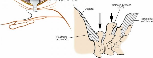
The head and neck are flexed to separate the occiput from the C1 posterior arch, providing adequate working space. Excessive flexion must be avoided to prevent overstretching of the spinal cord, especially in cases of severe instability or pre-existing stenosis. This position also helps reduce atlantoaxial subluxation.
- Mayfield Head Clamp: For stable fixation and precise head positioning. Care must be taken to avoid pin site complications (e.g., temporal artery injury).
-
Horseshoe Headrest:
Can be used for less rigid fixation or in cases where skull pins are contraindicated.
-
Cervical Alignment:
Ensure the cervical spine is in neutral alignment or mild flexion, maintaining physiological lordosis to avoid iatrogenic kyphosis. Intraoperative fluoroscopy or navigation can confirm optimal alignment.
- Padding: All pressure points are meticulously padded to prevent nerve palsies and skin breakdown.
- Intraoperative Monitoring: Somatosensory evoked potentials (SSEPs) and motor evoked potentials (MEPs) are highly recommended to monitor spinal cord function throughout the procedure, especially during positioning, reduction maneuvers, and instrumentation. C2 nerve root monitoring may also be considered.
- Fluoroscopy/Navigation: Pre-position the C-arm for AP and lateral views, or set up for intraoperative navigation, to facilitate accurate screw placement and confirm reduction.
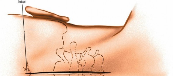
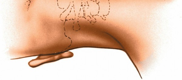
Landmarks and Incision
-
Palpable Landmarks:
- External Occipital Protuberance (EOP): High in the midline of the skull, indicating the superior extent of the operative field.
- Spinous Process of C2: The largest and most prominent spinous process in the upper cervical spine, providing a reliable midline landmark. While palpable as resistance, its distinct shape may be obscured by musculature.
-
C1 (Atlas):
Has no palpable spinous process. Its posterior arch lies deep to the EOP and superficial to the C2 spinous process.
-
Incision:
A midline longitudinal incision is typically made, centered over the C2 spinous process. The length of the incision extends from just below the EOP superiorly to approximately C3-C4 inferiorly, providing adequate exposure for C1 and C2.
Detailed Surgical Approach / Technique
The posterior C1-C2 approach involves a systematic dissection, meticulous identification of anatomical structures, and precise instrumentation.
1. Incision and Subcutaneous Dissection
- A sterile field is prepared. A skin incision is made along the previously marked midline.
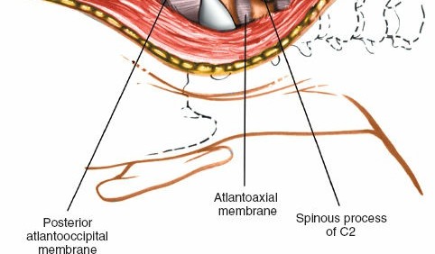
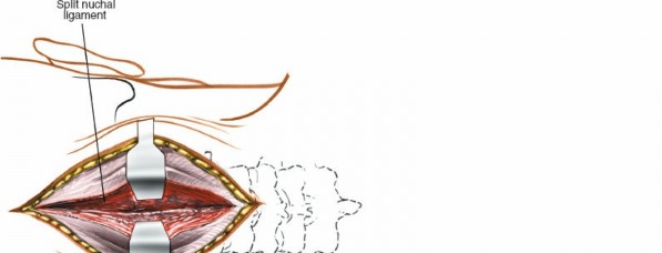
- The incision is carried through the subcutaneous tissue and the nuchal ligament, which is divided in the midline.
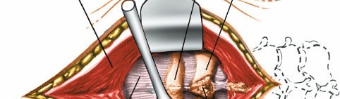
2. Muscle Dissection and Exposure
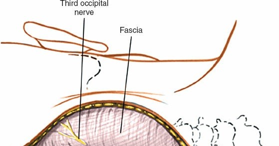
- Subperiosteal dissection begins by sharply incising the fascia over the spinous processes.
- The paraspinal muscles are meticulously stripped from the spinous processes and laminae of C2 and C3 using electrocautery and periosteal elevators. Subperiosteal dissection minimizes muscle trauma and bleeding.
-
Muscles Encountered:
- Superficial Layer: Trapezius, splenius capitis.
- Deep Layer: Semispinalis capitis (medial to splenius capitis).
- Suboccipital Muscles: Rectus capitis posterior major and minor, obliquus capitis superior and inferior. These muscles attach to C1 and C2.
- The C2 spinous process is identified. It serves as the primary orienting landmark.
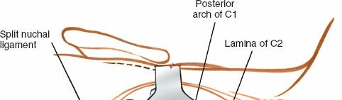
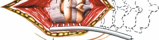
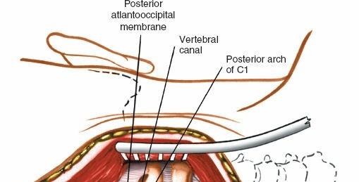
- Dissection proceeds superiorly along the C2 lamina to identify the C1 posterior arch . The posterior arch of C1 lies immediately superior to the C2 lamina, approximately 1-1.5 cm deep to the skin. It is essential to remain strictly subperiosteal and dissect laterally to expose the C1 posterior arch and lateral masses.
- The C2-C3 interspinous ligament and C3 spinous process are identified inferiorly to delineate the caudal extent of the exposure.
-
Laterally, the dissection extends to expose the lateral masses of C1 and the pars/pedicles of C2. Extreme caution is required during lateral dissection at C1 and C2 to avoid injury to the vertebral arteries, which course within the transverse foramina and over the C1 posterior arch.

3. Vertebral Artery Safeguarding
- The vertebral artery typically passes anterior to the C1-C2 facet joint and then curves posteriorly to lie in a groove on the posterior arch of C1.
- Before any bone work or screw placement, the anatomical course of the vertebral artery, as determined by pre-operative CTA, must be visualized and confirmed.
- The C1 posterior arch can be carefully decorticated for fusion purposes, but vigorous dissection or drilling laterally should be avoided, especially at the C1 sulcus.
- If decompression of the C1 posterior arch is required (e.g., for spinal cord compression), precise osteotomes or high-speed burrs are used, with meticulous attention to the vertebral artery.
4. Decompression (if indicated)
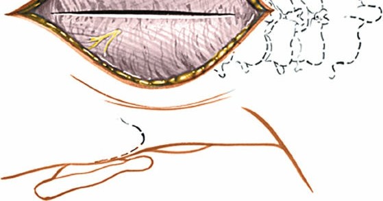
- C1 Posterior Arch Resection: If the posterior arch of C1 is impinging on the spinal cord (e.g., in basilar invagination or severe atlantoaxial instability), a laminectomy of C1 can be performed. This involves carefully resecting the posterior arch using a high-speed burr or rongeurs. The dura mater must be protected.
- C2 Laminectomy: Less commonly performed for isolated C2 compression posteriorly, but may be necessary in certain tumor resections or complex decompression scenarios.
5. Reduction of Atlantoaxial Instability
- If instability or subluxation is present, gentle reduction maneuvers are performed. This typically involves extension of the head and neck in the Mayfield clamp, combined with gentle posterior translation of C1 relative to C2.
- Intraoperative fluoroscopy or navigation is used to confirm adequate reduction.
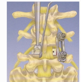
6. Instrumentation for Fusion (Goel-Harms Technique)
The C1 lateral mass and C2 pedicle/pars screw fixation (Goel-Harms technique) is the gold standard due to its superior biomechanical stability and high fusion rates.
A. C1 Lateral Mass Screw Placement
- C1 Exposure: Continue lateral dissection along the posterior arch of C1 until the lateral mass is clearly visualized. The posterior tubercle of C1 is often identified centrally, and the sulcus for the vertebral artery is superior and lateral.
-
Entry Point:
The entry point for the C1 lateral mass screw is typically at the junction of the posterior arch and the lateral mass, just inferior and medial to the C1 sulcus for the vertebral artery. This point is approximately 7-10 mm superior to the superior border of the C2 lamina and 15 mm lateral to the midline.

-
Trajectory:
The screw trajectory is directed anteriorly and slightly laterally, towards the anterior tubercle of C1. The medial wall of the lateral mass is the key landmark. The screw should be aimed towards the intersection of the anterior and middle thirds of the C1 lateral mass. The length of the screw is typically 30-36 mm.
- Awl/Drill: A high-speed burr or awl creates a pilot hole. A 2.0-2.5 mm drill bit is then advanced carefully, ensuring the drill bit remains within the bone using fluoroscopy or navigation.
- Probe: A pedicle probe is used to palpate all four walls of the pilot hole to confirm cortical integrity and absence of breach.
- Tap: The hole is tapped.
-
Screw Insertion:
A polyaxial screw (typically 3.5 mm or 4.0 mm diameter) is inserted.

B. C2 Pedicle/Pars Screw Placement
- C2 Exposure: The lamina, pars interarticularis, and superior articular facet of C2 are thoroughly exposed.
-
Entry Point (C2 Pedicle Screw):
The entry point is located at the intersection of the superior border of the C2 lamina and the lateral border of the inferior articular process. It is typically 2-3 mm inferior and 2-3 mm medial to the midpoint of the C2-C3 facet joint.
- Trajectory (C2 Pedicle Screw): Directed superiorly (approximately 20-30 degrees cephalad) and slightly medially (approximately 20-30 degrees towards the midline) to avoid the vertebral artery laterally and the spinal canal medially. The goal is to traverse the pedicle into the C2 vertebral body.
-
Entry Point (C2 Pars Screw):
The entry point is similar to the pedicle screw but may be slightly more lateral and inferior, aiming to stay within the pars interarticularis.
- Trajectory (C2 Pars Screw): Directed superiorly (approximately 30-45 degrees cephalad) and medially (approximately 30 degrees towards the midline) through the pars into the C2 body. This trajectory is often preferred to avoid the vertebral artery more reliably, as it typically passes anterior to the pedicle.
-
Awl/Drill, Probe, Tap, Screw Insertion:
Similar steps to C1 screw placement. The screw length for C2 pedicle/pars is typically 24-30 mm, with a diameter of 3.5-4.5 mm.
C. C2 Translaminar Screw (Alternative/Adjunct)
- Indication: When C2 pedicle/pars screws are contraindicated (e.g., aberrant vertebral artery, fracture of pars/pedicle), or as an adjunct for additional purchase.
- Entry Point: Located at the inferior border of the C2 spinous process, just lateral to the midline.
- Trajectory: Directed superiorly and medially across the C2 lamina into the contralateral lamina. Two screws can be placed, crossing in the midline.
- Technique: A small starting hole is created. A specialty translaminar drill bit (e.g., 2.5 mm) is advanced under fluoroscopic guidance to stay within the laminar bone. The screw is then inserted.
7. Rod Placement and Compression/Distraction
- Once all screws are placed bilaterally, appropriately sized connecting rods are contoured to match the cervical lordosis and connect the C1 and C2 screws.
- Set screws are loosely tightened.
- Compression across the C1-C2 interface or distraction (if needed for decompression) is applied, and final tightening of the set screws is performed.
- Confirmation of reduction and instrumentation is performed with intraoperative fluoroscopy or navigation.
8. Bone Grafting
- Decortication of the C1 posterior arch and C2 lamina/spinous process is performed to promote arthrodesis.
-
Autogenous bone graft (typically harvested from the posterior iliac crest or locally from the C2 spinous process) or allograft (cancellous chips, DBM) is packed around the C1-C2 facets and laminae.

9. Wound Closure
- Hemostasis is meticulously achieved.
- A subfascial drain may be placed to prevent hematoma formation.
- The muscular fascia is approximated in layers.
- The subcutaneous tissue and skin are closed in a standard fashion.
Complications & Management
Despite advances in technique and instrumentation, the posterior C1-C2 approach carries inherent risks due to the critical neural and vascular structures in the vicinity.
| Complication | Incidence (%) | Salvage Strategy / Management |
|---|---|---|
| Vertebral Artery (VA) Injury | 0.5-5 | Immediate pressure, packing with hemostatic agents (e.g., Gelfoam, Surgicel), consider direct repair or ligation (with pre-op assessment of contralateral VA dominance), post-op angiography and neurovascular intervention if needed. |
| Spinal Cord Injury | <1-2 | Immediate removal of offending hardware, urgent decompression, steroids, neurosurgical consultation. |
| C2 Nerve Root Injury/Neuralgia | 5-15 | Careful identification and protection, nerve root decompression/foraminotomy, post-op pain management (gabapentin, pregabalin), C2 neurectomy (rare). |
| Pseudarthrosis (Non-Union) | 5-10 | Revision surgery with additional bone graft, often augmented with biologics (e.g., BMP), consider extending fusion. |
| Hardware Failure (Screw pullout, rod fracture) | 2-10 | Revision surgery, re-instrumentation, consider different screw types/trajectories, extension of fusion. |
| Infection (Superficial/Deep) | 1-5 | Superficial: Wound care, oral antibiotics. Deep: Surgical debridement, IV antibiotics, possible hardware removal if persistent. |
| Dysphagia | 1-3 | Usually transient, related to C2 nerve irritation or prolonged intubation. Manage symptomatically. |
| Occipital/Cervical Pain (persistent) | Common | Aggressive post-op pain management, physical therapy, consider C2 neurectomy for persistent C2 neuralgia. |
| Dural Tear / CSF Leak | 1-2 | Primary repair with suture, dural sealant, careful wound closure, bed rest, lumbar drain if necessary. |
| Anesthetic/Positioning Complications | <1 | Vigilant monitoring, proper padding, cautious head positioning. |
Detailed Management:
- Vertebral Artery Injury: This is a catastrophic complication. If encountered intraoperatively, apply immediate direct pressure with a surgical sponge. Avoid blind clamping. If bleeding persists, packing with hemostatic agents (e.g., Surgicel, Gelfoam) and observation may suffice. If the vessel is transected, a vascular surgeon consultation for primary repair or ligation is necessary. Pre-operative CT angiography assessing contralateral VA dominance is critical. Post-operatively, monitor for signs of stroke.
- Spinal Cord Injury: Can result from direct trauma during dissection, excessive manipulation during reduction, or malposition of hardware. Vigilant intraoperative neurophysiological monitoring (SSEP/MEP) can provide early warning. If a deficit is noted, hardware is immediately removed, spinal alignment is re-assessed, and further decompression may be required. High-dose steroids may be considered.
- C2 Nerve Root Injury/Neuralgia: The C2 dorsal root ganglion and nerve are in close proximity to the C1-C2 joint and the C2 pars/pedicle entry points. Injury can lead to post-operative occipital neuralgia, dysesthesia, or numbness. Meticulous dissection and careful screw placement are essential. If persistent and intractable, C2 nerve root decompression or neurectomy can be considered.
- Pseudarthrosis: Non-union can lead to persistent pain, instability, and hardware failure. Risk factors include inadequate bone grafting, poor decortication, smoking, and systemic diseases. Management involves revision surgery with robust bone grafting (autograft preferred), potentially with biologics (e.g., rhBMP-2), and possibly extending the fusion construct.
- Hardware Failure: Screw pullout, loosening, or rod fracture can occur due to pseudarthrosis, osteopenia, or biomechanical overload. Revision surgery is typically required, often involving longer screws, different trajectories, or augmentation of the construct.
- Infection: Superficial infections are managed with wound care and antibiotics. Deep infections may require surgical debridement, prolonged intravenous antibiotics, and potentially hardware removal if the infection persists or involves the bone graft.
- Dural Tear/CSF Leak: Often identified intraoperatively, they should be repaired primarily with suture and reinforced with dural sealants. Post-operatively, strict bed rest and a lumbar drain may be required to facilitate healing and prevent CSF fistula formation.
- Dysphagia: Usually transient and multifactorial, possibly related to C2 nerve irritation, intubation trauma, or prevertebral soft tissue swelling. Most cases resolve spontaneously.
Post-Operative Rehabilitation Protocols
Post-operative management aims to optimize fusion rates, manage pain, and restore function while protecting the surgical construct.
1. Immediate Post-Operative Period (Days 0-7)
- Pain Management: Multimodal analgesia including opioids, NSAIDs (if not contraindicated for fusion), muscle relaxants, and neuropathic pain medications (gabapentin/pregabalin) for C2 neuralgia.
- Immobilization: A rigid cervical collar (e.g., Miami J or Aspen collar) is typically applied immediately post-operatively and worn full-time for 6-12 weeks, depending on the stability of the construct and the patient's bone quality. In some highly stable Goel-Harms constructs in healthy bone, a soft collar or no collar may be considered, but this is less common for C1-C2 fusions.
- Drain Management: Surgical drains are typically removed within 24-48 hours once output is minimal.
- Ambulation: Patients are encouraged to ambulate with assistance on post-operative day 1 to prevent complications such as deep vein thrombosis and pneumonia.
- Wound Care: Daily wound inspection for signs of infection.
2. Early Rehabilitation (Weeks 2-6)
- Collar Compliance: Strict adherence to collar wearing protocols is reinforced.
- Activity Restrictions: No heavy lifting (>5-10 lbs), no strenuous activities, no twisting or bending of the neck. Avoid driving until cleared by the surgeon.
- Physical Therapy (PT): May be initiated to address proximal joint mobility (shoulders, thoracic spine) and maintain general conditioning. Direct cervical range of motion (ROM) is usually restricted.
- Radiographic Follow-up: Plain radiographs (AP, lateral, odontoid) at 4-6 weeks to assess alignment and early signs of fusion.
3. Intermediate Rehabilitation (Weeks 6-12)
- Radiographic Assessment: Repeat radiographs at 10-12 weeks. If there are signs of early bony fusion and symptoms are improving, gradual weaning from the rigid collar may be considered.
- Gradual Activity Increase: Under the guidance of PT, gentle active cervical ROM exercises may be introduced, starting with isometric exercises and progressing to active-assisted and then active ROM, as tolerated and only after radiographic evidence of fusion.
- Strengthening: Progressive strengthening of shoulder girdle and periscapular muscles to support neck stability.
4. Late Rehabilitation (Months 3-6 and Beyond)
- Fusion Assessment: A CT scan at 3-6 months post-op is often used to definitively assess bony fusion. Criteria for fusion typically include bridging bone across the fusion mass and absence of lucencies around instrumentation.
- Collar Discontinuation: Once solid fusion is confirmed, the cervical collar can be fully discontinued.
- Progressive Strengthening and Conditioning: Focus on restoring full cervical range of motion (within limits of fusion), improving endurance, and functional strength. Proprioceptive exercises may be incorporated.
- Return to Activity: Gradual return to light recreational activities. High-impact sports or activities with a risk of head/neck trauma are generally discouraged or delayed until 6-12 months post-fusion, with surgeon approval.
- Long-term Follow-up: Periodic clinical and radiographic evaluations to monitor for adjacent segment degeneration or late complications.
Important Note: Smoking cessation is critical for optimal bone fusion. Patients who smoke should be strongly encouraged to quit pre-operatively and post-operatively, as nicotine significantly impairs bone healing.
Summary of Key Literature / Guidelines
The evolution of posterior C1-C2 fusion techniques reflects a continuous effort to improve stability, fusion rates, and patient outcomes while minimizing complications.
-
Early Techniques: Wiring techniques, such as the Gallie and Brooks techniques, were foundational.
- Gallie Fusion (1939): Utilizes sublaminar wires around C1 and C2 spinous process, securing a bone graft. High pseudarthrosis rates (up to 20-30%) and limited rotational stability were significant drawbacks.
- Brooks-Jenkins Fusion (1978): Involves interlaminar wiring and placement of bicortical bone grafts. Offered improved stability over Gallie but still had limitations.
- These techniques often required prolonged external immobilization (e.g., halo vest) and still had relatively high non-union rates.
-
Modern Screw-Rod Constructs: The introduction of screw-rod systems significantly advanced atlantoaxial fusion.
- Magerl/Harms Technique (1986): Described transarticular screw fixation for C1-C2. This technique provides excellent biomechanical stability but carries a risk of vertebral artery injury due to the challenging trajectory. It requires reduction to be achieved prior to screw insertion.
-
Goel-Harms Technique (Goel 1994, Harms and Melcher 2001):
The C1 lateral mass screw and C2 pedicle/pars screw construct revolutionized C1-C2 fusion. This technique offers:
- Superior Biomechanical Stability: Compared to wiring techniques and even transarticular screws, it provides immediate rigid fixation in all planes.
- High Fusion Rates: Reported rates consistently exceed 90-95%.
- Reduced Need for External Immobilization: Often allows for less restrictive cervical collars post-operatively.
- Reduced Vertebral Artery Risk: With proper pre-operative planning and intraoperative technique (CTA mapping, navigation, careful trajectory), the risk is minimized compared to transarticular screws. The C1 lateral mass screws are typically placed within the lateral mass, and C2 pars screws are often preferred over pedicle screws to avoid the vertebral artery.
- Numerous studies have validated the efficacy and safety of the Goel-Harms technique as the preferred method for atlantoaxial instability requiring posterior fusion.
-
Emerging Technologies:
- Navigation Systems (Fluoro-navigation, CT-navigation): Increasingly utilized to enhance screw placement accuracy, especially in complex anatomies or revisions, reducing the risk of vertebral artery or neural injury.
- Robotics: Still in early stages for cervical spine, but offers potential for increased precision.
- Biologics: The use of bone morphogenetic proteins (BMPs) and other osteoinductive agents to augment fusion in high-risk patients (e.g., smokers, revisions, poor bone quality) is gaining traction, though cost and potential complications (e.g., osteolysis, heterotopic ossification with high-dose BMP) remain considerations.
Current Guidelines: Consensus largely supports screw-rod constructs, particularly C1 lateral mass-C2 pedicle/pars screws, as the gold standard for achieving rigid atlantoaxial fusion. Pre-operative CT angiography for vertebral artery mapping is considered mandatory. Intraoperative neurophysiological monitoring and fluoroscopy/navigation are highly recommended to enhance safety. The choice between C2 pedicle or pars screws often depends on the patient's specific anatomy and the surgeon's preference regarding vertebral artery trajectory. For severe irreducible instability or C1 posterior arch compression, C1 laminectomy and occipital-C2 fusion may be considered if C1 fixation is not viable.
Clinical & Radiographic Imaging
You Might Also Like