Percutaneous Scaphoid Nonunion Repair: A Masterclass in Minimally Invasive Carpal Reconstruction
Key Takeaway
This masterclass guides fellows through percutaneous scaphoid nonunion repair for Grades I-III. We cover comprehensive anatomy, meticulous preoperative planning, and granular intraoperative execution. Learn precise guidewire placement, fracture reduction, arthroscopic evaluation, bone grafting, and stable headless screw fixation. Emphasis is placed on neurovascular protection, avoiding pitfalls, and ensuring robust fixation to prevent long-term arthritic progression.
Welcome, fellows, to the operating theater. Today, we're tackling a challenging yet rewarding pathology: the scaphoid nonunion. While seemingly straightforward, the scaphoid's unique anatomy, precarious blood supply, and critical role in carpal kinematics demand meticulous attention to detail. Our focus today will be on the percutaneous treatment of Grade I to III scaphoid nonunions, a technique that, when executed precisely, offers excellent outcomes with minimal soft tissue disruption.
Understanding the Scaphoid Nonunion: Diagnosis and Pathogenesis
Before we scrub in, let's briefly review the essentials. A scaphoid nonunion isn't a single entity; it's a spectrum of conditions. You'll recall from our didactic sessions the classification system that helps us stratify these injuries based on their characteristics and, crucially, guides our treatment strategy.
- Grade I (Delayed Presentation): Fractures presenting 4–12 weeks post-injury, often without significant resorption or sclerosis. These frequently respond well to screw fixation alone.
- Grade II (Fibrous): Characterized by an intact cartilaginous envelope but no significant sclerosis or resorption. These typically require percutaneous débridement, bone graft, and fixation.
- Grade III (Minimal Sclerosis/Resorption): Resorption less than 1 mm with minimal sclerosis. Similar to Grade II, these benefit from percutaneous débridement, bone graft, and fixation.
- Grade IV (Moderate Resorption/Sclerosis): Resorption up to 5 mm, but alignment is maintained, often with an intact fibrous envelope. These can sometimes be managed percutaneously, but open techniques may be necessary.
- Grades V and VI: These involve substantial bone loss, synovial pseudarthrosis, and significant flexion deformity, making them unsuitable for the percutaneous approach we'll demonstrate today. These often require open bone grafting, strut grafts, or even salvage procedures.
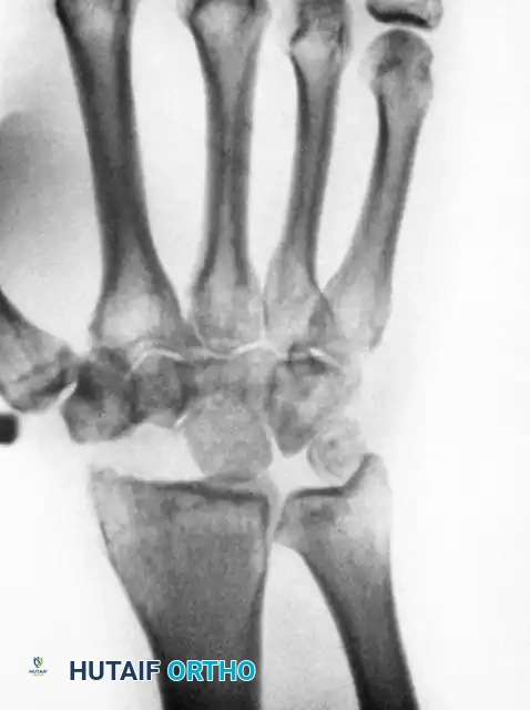
Imaging is paramount in our preoperative assessment. A CT scan with 1-mm slices in the plane of the scaphoid is indispensable. It provides exquisite detail of the bony anatomy, delineating the fracture gap, degree of sclerosis, and any early signs of healing or resorption. For assessing proximal pole vascularity, an MR with intravenous gadolinium contrast is our gold standard. The contrast uptake helps us determine if the proximal pole is viable or if avascular necrosis (AVN) is present.
Anatomy: The Scaphoid's Vulnerability
The scaphoid is a fascinating bone, almost entirely covered with articular cartilage, acting as the critical mechanical link between the proximal and distal carpal rows. Its blood supply is particularly relevant to nonunion development. It primarily receives blood from volar and dorsal arteries, entering distally. The volar artery supplies mainly the distal tubercle. However, the proximal pole is primarily dependent on intraosseous blood supply, a precarious arrangement akin to the femoral head, making it highly susceptible to AVN after fracture.
Pathogenesis: The fundamental culprits in scaphoid nonunion are mechanical instability and decreased perfusion. These factors form a vicious cycle: micromotion at the fracture site disrupts the delicate vascular perforators, leading to bone resorption, which further compromises mechanical stability. Proximal pole fractures are particularly vulnerable due to both a long distal lever arm acting on a small proximal contact area and their inherent vascular fragility.
Natural History: Without intervention, scaphoid nonunions often progress. Patients typically develop a dorsal intercalated segment instability (DISI) deformity of the carpus, similar to what we see in scapholunate ligament injuries. This progressive instability leads to scaphoid nonunion advanced collapse (SNAC) wrist arthritis over decades. We classify SNAC wrist into stages:
* Stage I: Arthritis affecting only the radial styloid.
* Stage II: Arthritis at the radioscaphoid joint.
* Stage III: Involvement of the scaphocapitate and capitolunate joints.
* Stage IV: Pancarpal arthritis, though often with preservation of the radiolunate joint.
Our surgical objective is to halt this progression by addressing the root causes.
Preoperative Planning: Precision is Key
Fellows, good surgery begins long before the first incision. For scaphoid nonunions, meticulous preoperative planning is non-negotiable.
- Patient History & Physical: Patients often present with chronic radial-sided wrist pain, sometimes unaware of a remote injury. On examination, you'll find radial-sided wrist tenderness, often in the anatomical snuffbox, and decreased range of motion, particularly extension, due to the developing DISI deformity.
- Imaging Review: Re-evaluate all advanced imaging (CT, MRI) to confirm the nonunion grade, assess bone quality, identify any AVN, and rule out other occult carpal fractures or significant degenerative changes. Advanced degenerative changes (e.g., SNAC Stage III or IV) are a relative contraindication to nonunion repair, as salvage procedures might be more appropriate.
- Surgical Goals: Our primary aims are threefold:
- Re-establishment of local perfusion: Guidewire placement and reaming help create channels for revascularization.
- Replacement of necrotic tissue: With an osteoconductive and osteoinductive matrix (bone graft).
- Stable fixation: To allow for undisturbed healing.
- Hardware Selection: We'll be using a headless cannulated compression screw. The specific length will be determined intraoperatively, but having a range of sizes available is crucial.
- Approach Planning:
- Proximal pole nonunions: Best approached dorsally to provide the most secure fixation, thinking of "securing the island to the mainland."
- Waist fractures: Can be treated either dorsally or volarly, depending on surgeon preference and fracture morphology.
- Distal pole nonunions: Though rare, are best approached volarly.
- Today, for a proximal pole nonunion, we will utilize the dorsal percutaneous approach.
Patient Positioning and Setup
Alright, team, let's get our patient positioned.
- Patient Position: The patient is placed supine on the operating table.
- Arm Setup: The affected arm is positioned on a dedicated hand table, ensuring adequate space for fluoroscopy and arthroscopy equipment. The shoulder is gently abducted, and the elbow is flexed to about 90 degrees.
- Traction Tower: For arthroscopy and to facilitate reduction, we'll use a traction tower (or a simple horizontal pulley system). This will apply controlled longitudinal traction to the wrist, typically with 12 pounds distributed among four finger traps (index, middle, ring, little fingers). This provides distraction of the carpal joints, improving visualization and maneuverability.
- Fluoroscopy Setup: The C-arm is brought into position, draped sterilely. We need to ensure unrestricted fluoroscopic views in multiple planes – AP, lateral, and oblique views (e.g., 45-degree pronated oblique for scaphoid visualization). We'll perform a preliminary fluoroscopic survey to re-evaluate the fracture, scaphoid alignment, and fragment mobility. This also allows us to identify any other occult carpal fractures.
Intraoperative Execution: The Percutaneous Masterclass
Now, let's get scrubbed in. We'll proceed systematically, step-by-step.
Step 1: Placement of Targeting Guidewires
Our initial objective is to establish a fluoroscopic "crosshair" to guide our central axis wire placement. This is critical for accurate screw trajectory.
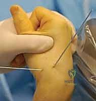
- Distal Fragment Targeting: We begin by placing a smooth 0.062-inch lateral targeting wire into the center of the distal scaphoid fragment, inserting it from radial to ulnar.
- Technique: Palpate the radial styloid and the distal scaphoid. Make a small stab incision if necessary. Advance the K-wire carefully, ensuring it is truly centered in the distal fragment on both AP and lateral fluoroscopic views.
- Proximal Fragment Targeting: Next, we'll ulnarly deviate the wrist to extend the distal fragment. Then, a smooth 0.062-inch dorsal-to-volar targeting Kirschner wire is placed into the center of the distal fragment.
- Technique: Identify the dorsal aspect of the scaphoid. Advance this wire from dorsal to volar, aiming for the center of the distal fragment.
- Rationale: Ulnar deviation helps open up the dorsal aspect of the scaphoid for easier wire placement and better visualization.
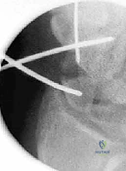
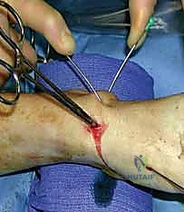
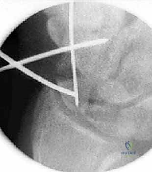
- Visual Check: These two Kirschner wires now form our "crosshair" target.
TECH FIG 1 • Crosshair targeting guide. A. External view.
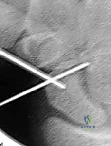
TECH FIG 1 • Crosshair targeting guide. B. AP view.
Step 2: Placement of the Distal Central Axis Derotation Wire
This first central axis wire will be a temporary tool for reduction and derotation, so absolute perfect central placement isn't required, but good alignment is always preferred.
- Identify Fracture Site: Under fluoroscopy, place a 19-gauge needle directly into the nonunion site. Confirm its position in the fracture gap on both AP and lateral views. This needle will serve as our initial guide.
- Introduce Derotation Wire: Using the needle's position as a landmark, introduce a double-cut 0.045-inch Kirschner wire into the fracture site.
- Approach: For a dorsal approach, we'll enter dorsally.
- Guidance: Drive this wire down the medullary canal of the distal fragment, using our previously placed distal crossed targeting wires as your external guides.
- Exit Point: The wire should exit at the base of the thumb, ensuring it's in an area devoid of critical neurovascular structures (superficial radial nerve, radial artery).
- Withdrawal: Once it exits, withdraw it carefully until its proximal tip is positioned precisely at the fracture site. This wire now helps maintain initial reduction and prevents rotation of the distal fragment.
Step 3: Fracture Reduction
Now, the crucial step of restoring anatomical alignment. This often involves a combination of external manipulation and internal joystick control.
- Proximal Joystick: From the dorsal aspect, drive a 0.062-inch Kirschner wire into the proximal fragment. This will serve as our "proximal joystick."
- Technique: Aim for a position that allows you to manipulate the proximal pole effectively. Perfect central placement is not necessary as this is a temporary wire.
- Correcting Deformity: The scaphoid nonunion often presents with a "humpback" deformity, where the distal fragment is palmar-flexed and the carpus is in DISI. We need to correct this.
- Maneuver: Flex the distal dorsal-to-volar targeting Kirschner wire (the one we placed earlier in the distal fragment) towards the newly placed proximal fragment joystick wire. This maneuver helps to extend the distal fragment and correct the flexion deformity.
- Maneuver: Flex the distal dorsal-to-volar targeting Kirschner wire (the one we placed earlier in the distal fragment) towards the newly placed proximal fragment joystick wire. This maneuver helps to extend the distal fragment and correct the flexion deformity.
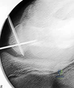
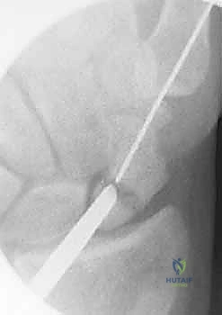
TECH FIG 2 • A. Fracture during reduction showing Kirschner wire positioned distally to capture reduction.
TECH FIG 2 • B. Fracture reduction with joysticks.
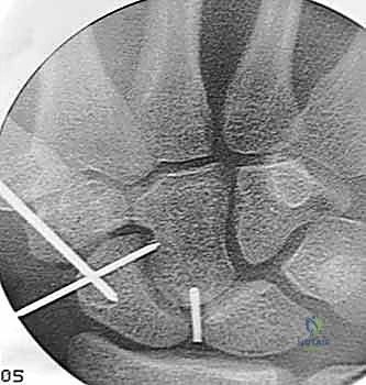
3. Secure Reduction: Once you achieve a satisfactory reduction, drive the distal fragment wire (the one exiting at the base of the thumb) retrograde into the proximal fragment. This secures the reduction temporarily.
* Fluoroscopic Confirmation: Confirm fragment position fluoroscopically in multiple views (AP, lateral, oblique) while holding the reduction. Ensure the scaphoid waist is well-aligned and the humpback deformity is corrected.
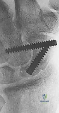
TECH FIG 2 • C. Radiograph of reduced fracture secured with a Kirschner wire.
4. Additional Leverage (If Needed): For stubborn translational deformities or significant displacement, a percutaneous snap (or a small periosteal elevator) may be introduced to provide additional leverage and fine-tune the reduction.
> Surgical Warning: Be mindful of surrounding soft tissues and neurovascular structures when using percutaneous instruments for reduction. Constant fluoroscopic guidance is essential.
Step 4: Placement of the Proximal Central Axis Guidewire
With the fracture reduced and temporarily secured, we now place the definitive central axis guidewire for our cannulated screw.
- Starting Point Identification: With the wrist partially flexed to expose the dorsal proximal pole and under fluoroscopy, impale a 19-gauge needle into the proximal ulnar corner of the proximal pole. This is our entry point.
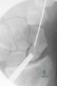
TECH FIG 3 • A. Radiograph of a needle used to identify starting position for central axis wire.
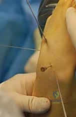
TECH FIG 3 • B. External view of starting position for central axis wire.
2. Guidewire Introduction: Introduce a 0.045-inch Kirschner wire through the needle's path.
* Trajectory: Drive this guidewire towards the thumb base, constantly correcting its direction based on the external crossed-wire targeting guide we established earlier. The goal is to traverse the scaphoid centrally.
* Confirmation: A successfully placed central axis scaphoid wire will intersect our crossing wires in the distal scaphoid.
* Exit Point: Continue driving the guidewire volarly past this intersection, through the trapezium, and ensure it exits safely at the thumb base in a zone devoid of neurovascular structures.
3. Wire Adjustment: Withdraw the guidewire until its trailing edge crosses the radiocarpal joint. At this point, the wrist can be safely extended without bending the wire.
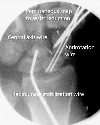
4. Dual Wire Construct: We now have two intramedullary Kirschner wires down the length of the scaphoid: one (the initial 0.045-inch wire) used to capture the initial reduction and the other (our new central axis 0.045-inch wire) placed down the long axis to be used as a guide for eventual screw insertion.
* Rationale: This use of two Kirschner wires provides an excellent antirotation construct during scaphoid reaming and screw placement, minimizing micromotion and improving stability.
TECH FIG 3 • C. Reduced fracture with antirotation wire.
Step 5: Arthroscopic Evaluation and Reaming
With our guidewires in place, we transition to arthroscopy for a detailed assessment and initial débridement.
- Arm Exsanguination & Traction: The arm is exsanguinated with an Esmarch bandage, and the tourniquet is inflated. The extremity is then placed in the traction tower with 12 pounds distributed between four finger traps, as previously set up.
- Portal Placement:
- Fluoroscopic Guidance: Use 19-gauge needles under fluoroscopy to precisely identify the radiocarpal and midcarpal portals. This minimizes iatrogenic injury from blind trocar insertion.
- Radial Midcarpal Portal: Introduce a small hemostat to gently separate soft tissues and enter the wrist joint. Insert a blunt trocar, followed by a small-joint angled arthroscope.
- Ulnar Midcarpal Portal: Introduce a probe here to evaluate carpal ligament competency.
- Outflow: Insert additional 19-gauge needles to establish outflow.
- Arthroscopic Evaluation:
- Fracture Reduction: Thoroughly evaluate the fracture reduction under direct arthroscopic visualization. Confirm smooth articular surfaces and good alignment.
- Fibrous Capsule: It is critical to determine the presence and integrity of a fibrous capsule around the nonunion site.
> Surgical Warning: If there is no intact fibrous capsule, percutaneous bone graft is contraindicated, as it will dissipate into the surrounding synovial fluid, rendering it ineffective. In such cases, an open approach with careful containment of the graft would be necessary. - Ligamentous Integrity: Use the probe to stress the attachments of the carpal ligaments, particularly the scapholunate interosseous ligament (SLIL). Any SLIL injury is graded using the Geissler grading system.
- Grade I & II: Treated with débridement and thermal shrinkage (capsulorrhaphy) alone.
- Grade III: Treated with débridement, and after fracture repair, carpal pinning for 6 weeks (e.g., K-wire from scaphoid to lunate).
- Grade IV: Requires open repair of the dorsal SLIL ligament, potentially with capsulodesis.
- Proximal Pole Vascularity: This is a crucial step.
- Maneuver: While keeping the wrist in a flexed position in the traction tower, retrograde the central axis guidewire so it is equally exposed dorsally and volarly.
- Reaming: Drive the central axis guidewire retrograde through the proximal fragment. Ream over this wire to the level of the nonunion site.
- Inspection: Withdraw the central axis wire to the fracture site (keeping the derotation K-wire in place to maintain reduction). Now, introduce the scope into the proximal fragment through the previously reamed tract.
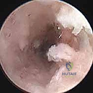
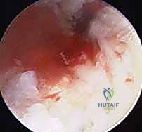
- Vascularity Check: Stop the inflow of irrigation fluid and let down the tourniquet. Carefully inspect the cancellous bone of the proximal pole with the arthroscope for the appearance of punctate bleeding. This is our direct visual confirmation of proximal pole vascularity.
TECH FIG 4 • Inspect the cancellous bone of the proximal pole with the scope for the appearance of punctate bleeding. A. Devascularized proximal pole with no punctate bleeding.
TECH FIG 4 • Inspect the cancellous bone of the proximal pole with the scope for the appearance of punctate bleeding. B. Vascularized proximal pole.
Another view of vascularity check.
Another view of vascularity check.
> Clinical Pearl: The presence of punctate bleeding indicates viable bone, allowing healing via creeping substitution. Absence of bleeding, especially in a proximal pole nonunion, might necessitate consideration of a vascularized bone graft, though rigid fixation and nonvascularized graft can still succeed in early AVN.
4. Distal Reaming: Hand ream, under fluoroscopy, over the central axis wire to within 2 mm of the distal cortex. This prepares the distal canal for the screw. Then, withdraw the central axis wire volarly back to the level of the fracture site.
Step 6: Débridement of the Nonunion Site and Bone Grafting
For Grade II and III nonunions, débridement and bone grafting are essential. Grade I nonunions (delayed presentation) typically do not require débridement or grafting.
- Débridement: Insert a small curved curette through the path that was just reamed in the proximal pole. Carefully débride the nonunion site, removing any fibrous tissue, sclerotic bone, or necrotic fragments.
- Technique: Work meticulously, ensuring you create healthy, bleeding bone surfaces.
- Preservation: Crucially, avoid disrupting the peripheral fibrous shell. This intact shell creates a contained cavity, essential for packing the bone graft and preventing its extrusion into the synovial fluid.
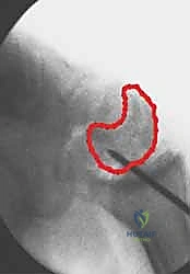
TECH FIG 5 • A. Percutaneous curette of nonunion.
2. Bone Graft Harvest: Using an 8-gauge bone biopsy needle, harvest cores of cancellous bone. Our preferred donor sites are the distal radius (ipsilateral, easily accessible, good quality cancellous bone) or the iliac crest for larger volumes or if local graft is inadequate.
3. Bone Graft Insertion: Introduce the bone biopsy cannula into the reamed proximal pole tract. Pack plugs of the harvested cancellous bone graft through the cannula into the nonunion site.
* Fluoroscopic Guidance: Continuously monitor with fluoroscopy. Pack until the radiolucent image of the nonunion site becomes radiopaque, indicating a densely packed graft.
TECH FIG 5 • B. Nonunion site filled with percutaneous bone graft.
> Clinical Pearl: Adequate packing of the bone graft is crucial for osteoconduction and osteoinduction. Ensure no voids remain.
Step 7: Final Reaming and Fixation
With the nonunion débrided and grafted, we proceed to definitive fixation.
- Central Axis Wire Adjustment: The wrist is flexed, and the central axis scaphoid guidewire (the one exiting at the base of the thumb) is driven dorsally. Adjust the wire until its trailing end is securely positioned in the subchondral bone of the distal scaphoid pole.
- Scaphoid Length Measurement: Place a second K-wire of equal length percutaneously against the proximal scaphoid pole, next to and parallel with the guidewire. The difference in length between the trailing end of each wire represents the true scaphoid length.
- Screw Length Calculation: The screw length selected should be 4 mm less than the measured scaphoid length. This allows for 2 mm of clearance at each end of the scaphoid, ensuring complete implantation without screw prominence into the joint space.
Surgical Pitfall: The most common reported complication of percutaneous screw stabilization for scaphoid fractures is implantation of a screw that is too long. A prominent screw can cause significant articular damage and pain. Always double-check your measurements and ensure adequate clearance.
- Screw Length Calculation: The screw length selected should be 4 mm less than the measured scaphoid length. This allows for 2 mm of clearance at each end of the scaphoid, ensuring complete implantation without screw prominence into the joint space.
- Full Path Reaming: Advance the central axis wire so it is exposed equally volar and dorsal. Now, re-ream the entire path of the screw to within 2 mm of the opposite cortex.
- Rationale: This creates a smooth, clear path through the bone graft for the screw. Attempting to advance a blunt screw directly through a densely packed graft can "explode" the graft through the cortical shell, compromising your construct.
- Screw Insertion: Place the headless cannulated compression screw over the central axis guidewire.
- Screw Type: A standard-size Acutrak screw is excellent for resisting flexion moments, providing robust compression.
- Compression Technique: In unstable nonunions, as the screw
Additional Intraoperative Imaging & Surgical Steps
REFERENCES
-
Clinical symptoms are also not a reliable indicator of healing. Rigid fixation alone may provide a painless wrist after surgery before actual bridging bone has occurred.
-
Contact sports and heavy labor are restricted until healing is confirmed on CT.
OUTCOMES
- The only published series of nonunions treated percutaneously is a select series of 15 patients with minimal resorption treated with screw fixation alone. All healed, as demonstrated by bridging bone on CT scans. 3
-
Screws placed outside the central axis have less stable fixation and therefore an increased risk of nonunion.
-
A screw that is too long risks wear of the radioscaphoid joint.
-
Bond CD, Shin AY, McBride MT, et al. Percutaneous screw fixation or cast immobilization for nondisplaced scaphoid fractures. J Bone Joint Surg Am 2001;83:483–488.
-
Geissler WB, Freeland AE, Savoie FH, et al. Intracarpal soft-tissue lesions associated with an intra-articular fracture of the distal end of the radius. J Bone Joint Surg Am 1996;78A:357–365.
-
Slade JF III, Geissler WB, Gutow AP, et al. Percutaneous internal fixation of selected scaphoid nonunions with an arthroscopically assisted dorsal approach. J Bone Joint Surg Am 2003;85A(Suppl 4):20–32.
-
Toby EB, Butler TE, McCormack TJ, et al. A comparison of fixation screws for the scaphoid during application of cyclic bending loads. J Bone Joint Surg Am 1997;79A:1190–1197.
You Might Also Like