Total Hip Arthroplasty: Component Design & Selection
Key Takeaway
The selection of total hip arthroplasty components requires a profound understanding of hip biomechanics, implant metallurgy, and patient-specific anatomy. This guide details the critical design features of femoral and acetabular implants, including offset, version, modularity, and fixation philosophies. By mastering these principles, orthopaedic surgeons can optimize joint stability, restore normal kinematics, and ensure long-term survivorship of the prosthesis while minimizing complications such as impingement and dislocation.
Introduction to Total Hip Component Selection
The modern orthopaedic surgeon is presented with a vast armamentarium of total hip femoral and acetabular components, encompassing a multitude of materials, geometries, and fixation philosophies. While few implant designs prove to be universally superior, specific design features confer distinct biomechanical advantages in selected clinical scenarios. Properly selected and meticulously implanted total hip components yield satisfactory, long-lasting results in an overwhelmingly high percentage of patients.
However, no single implant system is appropriate for every patient. A comprehensive understanding of component designs, their inherent strengths, and their biomechanical weaknesses is a mandatory asset for the practicing arthroplasty surgeon. Selection must be rigorously tailored to the patient’s physiological age, anticipated longevity, functional demands, bone quality (e.g., Dorr classification), and proximal femoral morphometry.
Clinical Pearl: The surgeon’s recommendations should always be tempered by the knowledge that "new" does not inherently mean "better." Radical departures from proven concepts of implant design often yield unpredictable long-term survivorship. Evidence-based registry data should drive implant selection over industry marketing.
Furthermore, the economic burden of total hip arthroplasty (THA) cannot be ignored. With the institution of diagnosis-related group (DRG) payments, implants alone may account for up to 40% of the total compensation provided by healthcare systems like Medicare. The American Academy of Orthopaedic Surgeons (AAOS) explicitly states in its "Position Statement on Containing the Cost of Orthopaedic Implants" that while the final authority for selecting implants rests with the treating physician, surgeons must work collaboratively with hospital administrators to adopt reasonable, cost-effective criteria based on individual patient needs.
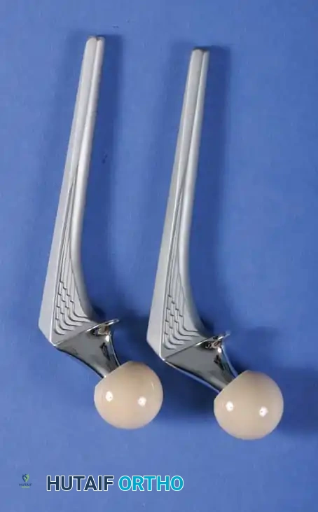
Biomechanics of the Femoral Component
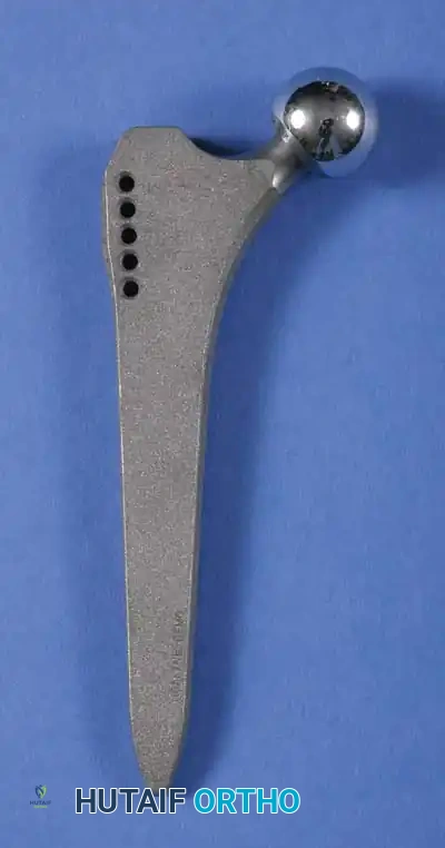
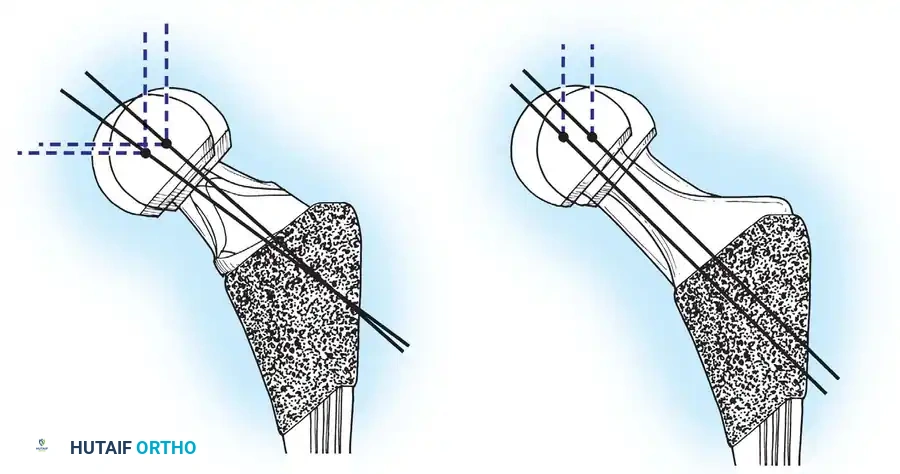
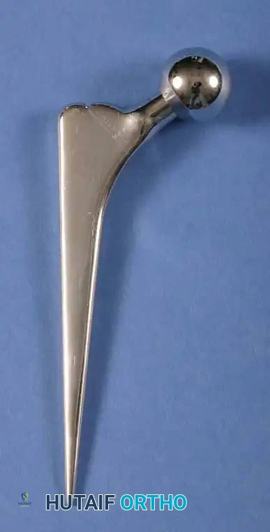
The primary function of the femoral component is the anatomical replacement of the arthritic or necrotic femoral head and neck. The ultimate goal—a biomechanically sound, stable, and impingement-free hip joint—is accomplished by meticulous restoration of the normal center of rotation.
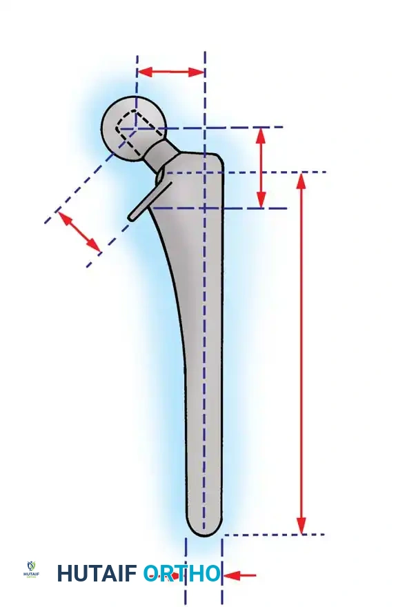
The center of rotation is dictated by three critical spatial parameters:
1. Vertical Height (Vertical Offset): Determines leg length.
2. Medial Offset (Horizontal Offset): Determines abductor tension and joint reaction force.
3. Femoral Neck Version: Determines anterior/posterior stability.
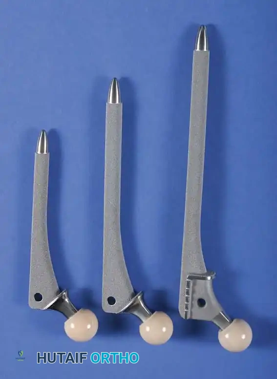
Vertical Height and Leg Length
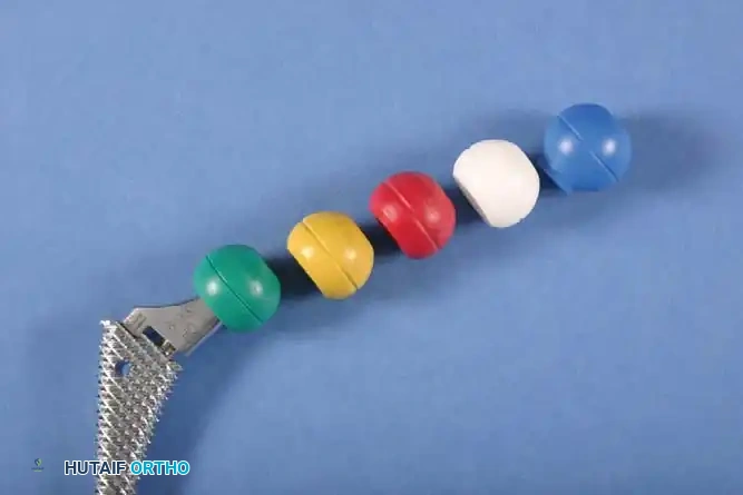
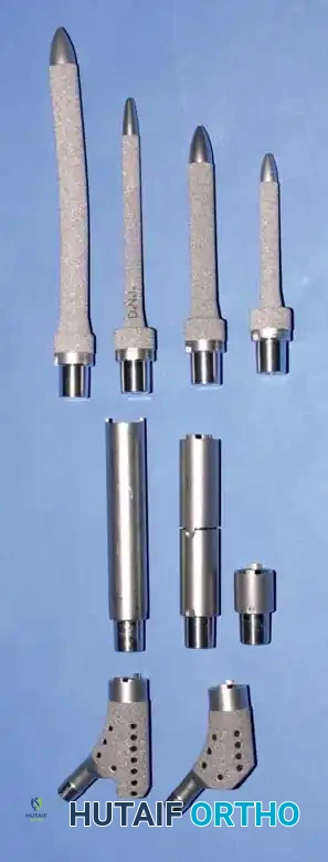
Vertical height and offset increase simultaneously as the prosthetic neck is lengthened. Proper reconstruction of both features is the primary goal during preoperative templating and intraoperative trialing. In contemporary modular systems, neck length is adjusted using modular femoral heads with variable internal recesses that engage a Morse taper on the stem's trunnion. Neck lengths typically range from 25 to 50 mm, allowing intraoperative adjustments of 8 to 12 mm.
When utilizing cemented stems, vertical height can be further fine-tuned by varying the depth of insertion or the level of the femoral neck osteotomy. Conversely, cementless press-fit components rely on metaphyseal diaphyseal engagement, meaning the depth of insertion is dictated by the patient's endosteal anatomy rather than the surgeon's osteotomy level.
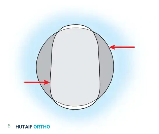
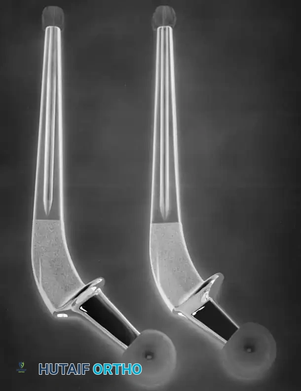
Medial Offset (Horizontal Offset)
Offset is defined as the perpendicular distance from the center of the femoral head to a line bisecting the long axis of the distal femoral stem. Inadequate restoration of offset shortens the moment arm of the abductor musculature.
Surgical Warning: Failure to restore adequate offset results in a decreased abductor moment arm, leading to a compensatory increase in joint reaction forces. Clinically, this manifests as a Trendelenburg gait (limp), increased polyethylene wear, and premature bony impingement, which dramatically increases the risk of dislocation.
To address anatomical variances, manufacturers provide stems in "standard" and "high-offset" configurations. High offset is typically achieved by reducing the neck-stem angle (e.g., from 135 degrees to 127 degrees) or by medializing the attachment point of the neck to the stem body.
Femoral Neck Version
Version refers to the orientation of the femoral neck relative to the coronal plane. The native femur typically exhibits 10 to 15 degrees of anteversion. Restoring this anteversion is paramount for joint stability.
With cemented stems, the surgeon can freely dictate version during cement curing. However, with cementless proximally coated stems, the version is largely dictated by the native anatomy of the proximal femur to maximize endosteal fill and rotational stability. If the native version is highly abnormal (e.g., severe retroversion in developmental dysplasia), modular stems that allow independent rotation of the metaphyseal and diaphyseal segments may be required.
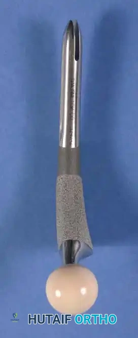
Head Size, Neck Geometry, and Impingement
The size of the femoral head, the head-to-neck ratio, and the cross-sectional geometry of the prosthetic neck profoundly influence the impingement-free range of motion (ROM). Impingement between the prosthetic neck and the acetabular rim leads to subluxation, accelerated wear, liner fracture, and catastrophic dislocation.
The Role of Femoral Head Diameter
The introduction of highly cross-linked polyethylene (HXLPE) and advanced ceramic bearings has facilitated the use of larger femoral heads without the historical penalty of unacceptable volumetric wear. Increasing the head size from 28 mm to 32 mm or 36 mm significantly increases the "jump distance" (the distance the head must travel to dislocate) and improves impingement-free flexion and internal rotation.
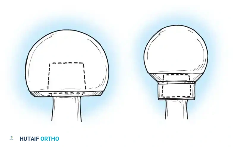
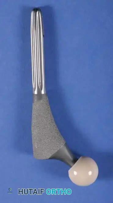
Neck Geometry: Circular vs. Trapezoidal
The shape of the femoral neck is equally critical. A circular neck geometry reduces the clearance space, leading to earlier impingement. Modern stems utilize a trapezoidal or flats-sided neck design, which maximizes the head-to-neck ratio and allows for a greater arc of motion before the neck contacts the acetabular liner.
The Danger of Skirted Heads
When extreme neck lengths are required (e.g., +12 mm or +16 mm heads), the modular head often features an extended "skirt" to cover the trunnion. This skirt effectively increases the diameter of the femoral neck, drastically reducing the head-to-neck ratio and severely limiting ROM.
Pitfall: Avoid skirted modular heads whenever possible. If a skirted head is required to achieve stability, the surgeon must re-evaluate the stem depth, offset, or acetabular component positioning, as the skirt will cause early mechanical impingement and risk levering the hip out of the socket.
Fixation Philosophies: Cemented vs. Cementless
All contemporary total hip systems achieve fixation via a metallic stem inserted into the medullary canal. The evolution of implant longevity has been driven by advancements in the prosthesis-bone interface.
Cemented Femoral Stems
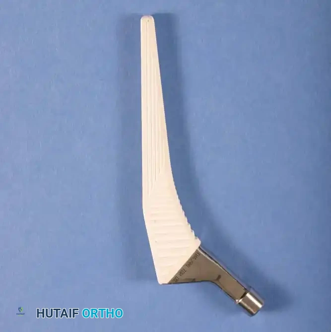
Since the advent of Sir John Charnley's low-friction arthroplasty, polymethyl methacrylate (PMMA) bone cement has been a reliable standard. Modern cementing techniques (third-generation cementing) involve pulsatile lavage, distal canal plugging, retrograde cement injection, and pressurization.
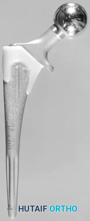
Design Rationale for Cemented Stems:
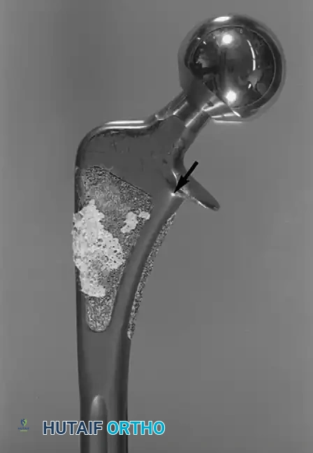
* Material: High-strength superalloys, predominantly Cobalt-Chromium (CoCr), are favored. The higher modulus of elasticity of CoCr reduces stresses within the proximal cement mantle compared to titanium.
* Geometry: A broad medial border and a broad lateral border are preferred to load the proximal cement mantle in compression rather than shear. Sharp edges must be avoided as they act as stress risers, initiating cement mantle fractures.
* Surface Finish: Polished stems (e.g., Exeter philosophy) are designed to subside slightly within the cement mantle, maintaining compressive forces. Conversely, composite-beam designs utilize surface macrotexturing to bond rigidly to the cement.
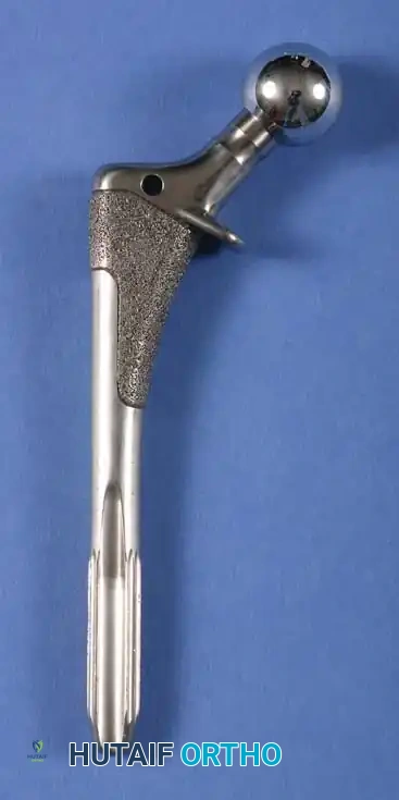
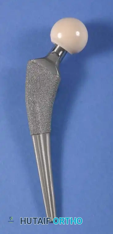
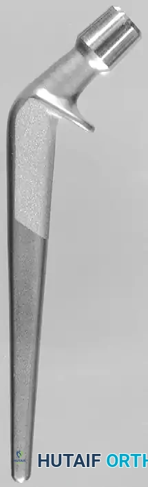
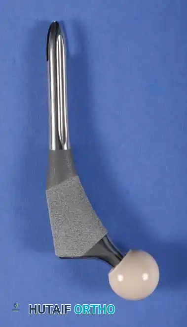
Cementless (Press-Fit) Femoral Stems
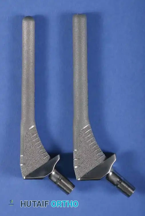
Cementless stems rely on initial mechanical stability (press-fit) followed by secondary biological fixation (osseointegration). These stems are typically manufactured from Titanium alloy (Ti-6Al-4V) due to its excellent biocompatibility and lower modulus of elasticity, which reduces proximal stress shielding.
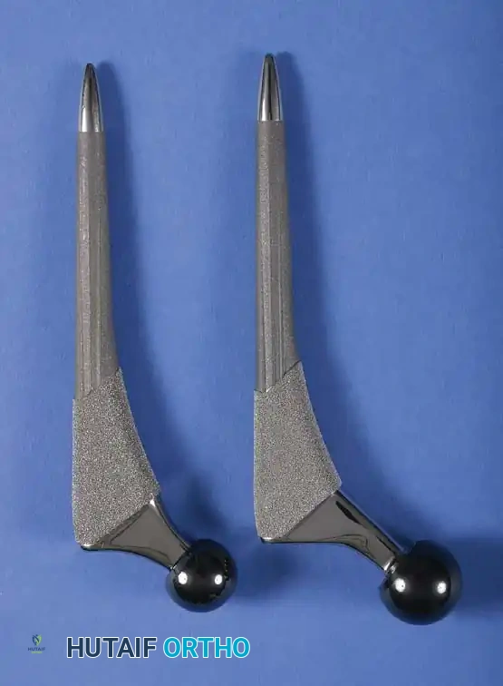
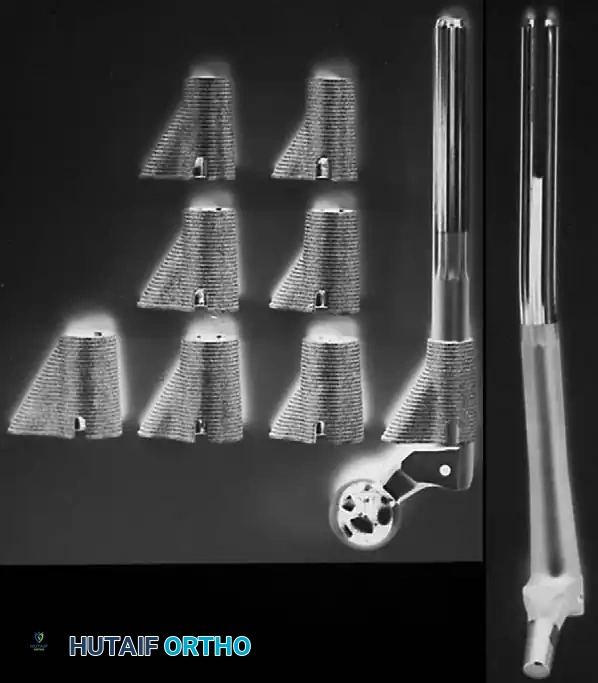
Types of Cementless Stems:
1. Single-Wedge (Tapered Flat): Provides excellent mediolateral fill and rotational stability. Ideal for Dorr Type A and B bone.
2. Double-Wedge (Fit-and-Fill): Engages the metaphysis in both the AP and ML planes.
3. Cylindrical Fully Porous Coated: Historically used for revision or severe diaphyseal engaging scenarios.
4. Modular Stems: Allow independent sizing of the metaphyseal and diaphyseal segments, crucial for complex deformities.
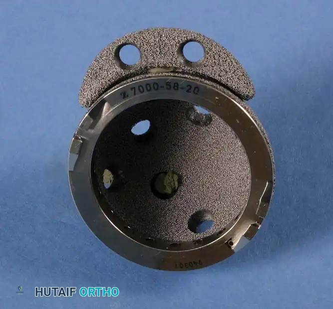
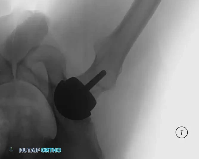
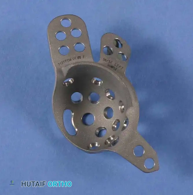
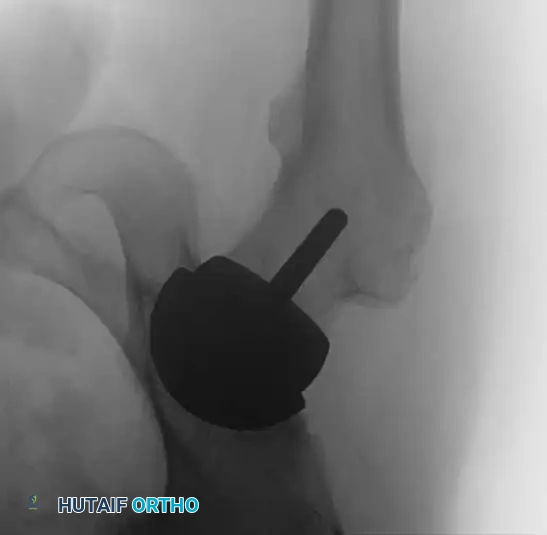
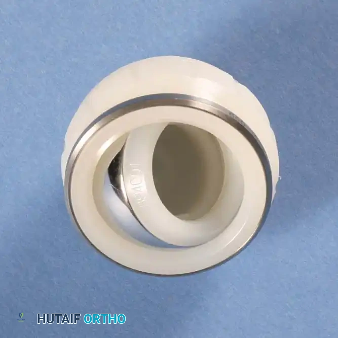
Acetabular Component Design
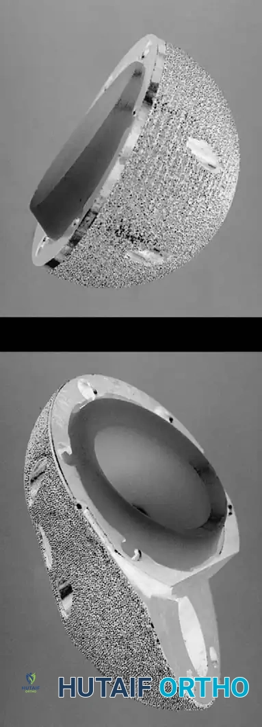
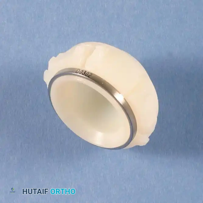
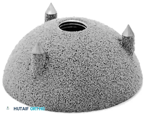
The acetabular component must provide a stable, low-friction articulation while ensuring rigid fixation to the host pelvis. Modern systems predominantly utilize a modular design: a titanium alloy hemispherical shell with a porous coating for bone ingrowth, coupled with a modular bearing liner.
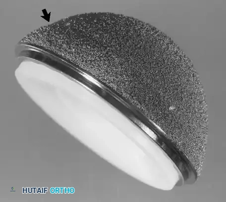
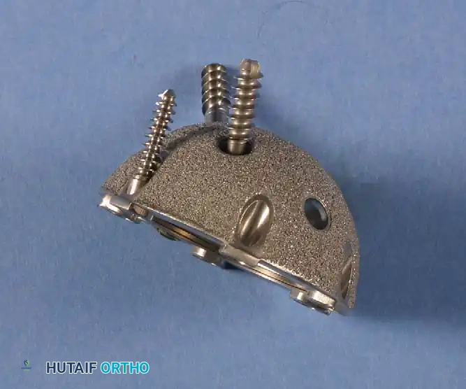
Hemispherical Shells and Fixation
The titanium shell is under-reamed by 1 to 2 mm relative to the final implant size to achieve an equatorial press-fit. The porous surface (sintered beads, plasma spray, or highly porous trabecular metal) facilitates osteoblast migration and rigid osseointegration. Supplemental fixation can be achieved using titanium cancellous screws placed through the "safe zone" (posterosuperior quadrant) to avoid neurovascular injury.
Bearing Surfaces
The choice of articulation significantly impacts the longevity of the THA.
* Metal-on-Polyethylene (MoP): The historical gold standard. Modern Highly Cross-Linked Polyethylene (HXLPE) has virtually eliminated osteolysis caused by wear debris.
* Ceramic-on-Polyethylene (CoP): Offers superior scratch resistance and lower wear rates than MoP.
* Ceramic-on-Ceramic (CoC): The lowest wear rates available. Ideal for young, highly active patients. However, risks include ceramic fracture and "squeaking."
Surgical Technique and Positioning
Meticulous surgical technique is the ultimate determinant of implant success.
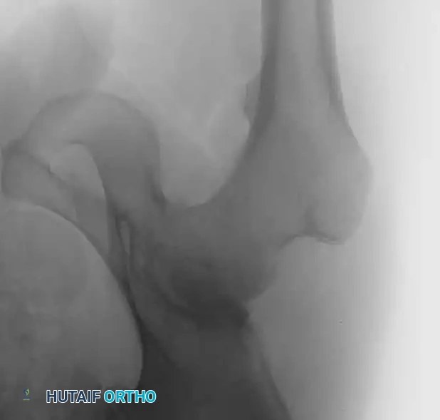
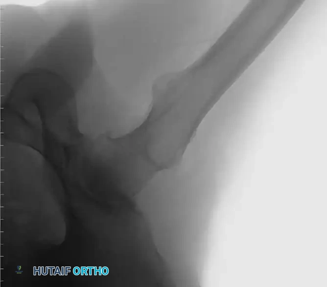
Preoperative Templating
Digital templating is mandatory. It establishes the anticipated center of rotation, leg length discrepancy, required offset, and approximate component sizes. The surgeon must template both the AP pelvis and the cross-table lateral to assess the medullary canal diameter and anterior bow.
Patient Positioning and Approach
- Posterior Approach: Performed in the lateral decubitus position. Offers excellent expansile exposure of the femur. Requires meticulous repair of the short external rotators and capsule to minimize posterior dislocation risk.
- Direct Anterior Approach (DAA): Performed supine, often on a specialized traction table. Utilizes the internervous plane between the TFL and Sartorius. Associated with lower early dislocation rates and faster immediate mobilization, though it carries a learning curve and risk to the lateral femoral cutaneous nerve.
- Anterolateral Approach (Hardinge): Performed supine or lateral. Excellent stability but risks abductor weakness or heterotopic ossification.
Femoral Preparation and Trialing
Once the acetabulum is reconstructed, the femur is elevated and prepared.
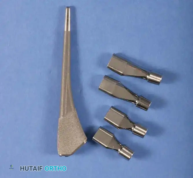
1. Box Osteotome: Used to open the femoral canal laterally, ensuring neutral alignment and preventing varus malposition.
2. Broaching: Sequential broaching is performed until rotational stability and cortical chatter are achieved.
3. Trialing: Trial necks and heads are applied. The hip is reduced and taken through a full ROM to assess stability, impingement, and soft tissue tension (the "shuck" test).
Postoperative Protocols and Rehabilitation
Immediate postoperative management focuses on rapid mobilization, pain control, and complication prevention.
Weight-Bearing and Mobilization
Most patients undergoing primary THA with cementless or cemented components are allowed weight-bearing as tolerated (WBAT) immediately postoperatively. Early mobilization (day 0 or day 1) significantly reduces the risk of deep vein thrombosis (DVT) and pulmonary embolism (PE).
Dislocation Precautions
Historically, strict "hip precautions" were enforced for 6 to 12 weeks.
* Posterior Approach: Avoid flexion past 90 degrees, internal rotation, and adduction across the midline.
* Anterior Approach: Avoid extreme extension and external rotation.
Modern literature suggests that with large diameter heads (≥32 mm) and meticulous soft tissue repair, strict precautions may be relaxed, improving patient satisfaction without increasing dislocation rates.

📚 Medical References
- total hip components, J Arthroplasty 3:249, 1988.
- Crowninshield RD, Brand RA, Pedersen DR: A stress analysis of acetabular reconstruction in protrusio acetabuli, J Bone Joint Surg 65A:495, 1983.
- Crowninshield RD, Johnston RC, Brand RA, et al: An engineering analysis of total hip component design, Orthop Rev 12:33, 1983.
- Cuckler JM, Bearcroft J, Asgian CM: Femoral head technologies to reduce polyethylene wear in total hip arthroplasty, Clin Orthop Relat Res 317:57, 1995.
- Cuckler JM, Moore KD, Lombardi AV, et al: Large versus small femoral heads in metal-on-metal total hip arthroplasty, J Arthroplasty 19:41, 2004.
- D’Antonio J, Capello W, Manley M, et al: Alumina ceramic bearings for total hip arthroplasty: fi ve-year results of a prospective randomized study, Clin Orthop Relat Res 436:164, 2005.
- Davey JR, O’Connor DO, Burke DW, et al: Femoral component offset: its effect on strain in bone-cement, J Arthroplasty 8:23, 1993.
- Delaunay CP: Metal-on-metal bearings in cementless primary total hip arthroplasty, J Arthroplasty 19:35, 2004.
- Digas G, Kärrholm J, Thanner J, et al: The Otto Aufranc Award. Highly cross-linked polyethylene in total hip arthroplasty: randomized evaluation of penetration rate in cemented and uncemented sockets using radiostereometric analysis, Clin Orthop Relat Res 429:6, 2004.
- Dorlot J, Christel P, Meunier A: Wear analysis of retrieved alumina heads and sockets of hip prostheses, J Biomed Mater Res 23:299, 1989.
- Dumbleton J, Manley MT: Current concepts review: hydroxyapatite-coated prostheses in total hip and knee arthroplasty, J Bone Joint Surg 86A:2527, 2006.
- Engh CA, Bobyn JD: The infl uence of stem size and extent of porous coating on femoral bone resorption after primary cementless hip arthroplasty, Clin Orthop Relat Res 231:7, 1988.
- Engh CA, Bobyn JD, Glassman AH: Porous-coated hip replacement: the factors governing bone ingrowth, stress shielding, and clinical results, J Bone Joint Surg 69B:45, 1987.
- Engh CA, Glassman AH, Suthers KE: The case for porouscoated hip implants, Clin Orthop Relat Res 261:63, 1990.
- Engh CA, McGovern TF, Bobyn JD, et al: A quantitative evaluation of periprosthetic bone-remodeling after cementless total hip arthroplasty, J Bone Joint Surg 74A:1009, 1992.
- Engh CA, Sychterz C, Engh C: Factors affecting femoral bone remodeling after cementless total hip arthroplasty, J Arthroplasty 14:637, 1999.
- Engh CA, Young AM, Engh CA, et al: Clinical consequences of stress shielding after porous-coated total hip arthroplasty, Clin Orthop Relat Res 417:157, 2003.
- Galante JO, Rostoker W: Wear rates of candidate materials for total hip arthroplasty. In The hip, St Louis, 1973, Mosby. Gilbert JL, Bukley CA, Jacobs JJ, et al: Intergranular corrosionfatigue failure of cobalt-alloy femoral stems, J Bone Joint Surg 76A:110, 1994.
- Hallab NJ, Anderson S, Caicedo M, et al: Immune responses correlate with serum-metal in metal-on-metal hip arthroplasty, J Arthroplasty 19:88, 2004.
- Hamadouche M, Boutin P, Daussange J, et al: Alumina-onalumina total hip arthroplasty: a minimum 18.5-year followup study, J Bone Joint Surg 84A:69, 2002.
- Harris WH, Maloney WJ: Hybrid total hip arthroplasty, Clin Orthop Relat Res 249:21, 1989.
- Harris WH, Penenberg BL: Further follow-up on socket fi xation using a metal-backed acetabular component for total hip replacement, J Bone Joint Surg 69A:1140, 1987.
- Heck DA, Partridge CM, Reuben JD, et al: Prosthetic component failures in hip arthroplasty surgery, J Arthroplasty 10:575, 1995.
- Hrlmer P, Nielsen PT: Fracture of ceramic femoral heads in total hip arthroplasty, J Arthroplasty 8:567, 1993.
- Ito H, Matsuno T, Minami A: Pre-coated femoral components in hybrid total hip arthroplasty: results at 11 years, J Bone Joint Surg 87B:306, 2005.
- Jasty M, Engh C, Harris W: Femoral bone remodeling after total hip arthroplasty: the skeletal response to well-fi xed cemented and cementless components. Paper presented at the Twentyfourth Open Scientifi c Meeting of the Hip Society, Atlanta, 1996.
- Jinnah RH, Tooke MS: Indications for custom total hip arthroplasty. In Advances in orthopaedic surgery, Baltimore, 1988, Williams & Wilkins. Johnston RC, Brand RA, Crowninshield RD: Reconstruction of the hip: a mathematical approach to determine optimum geometric relationships, J Bone Joint Surg 61A:639, 1979.
- Krushell RJ, Burke DW, Harris WH: Range of motion in contemporary total hip arthroplasty, J Arthroplasty 6:97, 1991.
- Lachiewicz PF, Kelley SS: The use of constrained components in total hip arthroplasty, J Am Acad Orthop Surg 10:233, 2002.
- Ladon D, Doherty A, Newson R, et al: Changes in metal levels and chromosome aberrations in the peripheral blood of patients after metal-on-metal hip arthroplasty, J Arthroplasty 19:78, 2004.
- Lavernia C, D’Apuzzo M, Hernandez V, et al: Thigh pain in primary total hip arthroplasty: the effects of elastic moduli, J Arthroplasty 19:10, 2004.
- Lewis JL, Askew MJ, Wixson RL, et al: The infl uence of prosthetic stem stiffness and of a calcar collar on stresses in the proximal end of the femur with a cemented femoral component, J Bone Joint Surg 66A:280, 1984.
- Lidgren L, Drar H, Möller J: Strength of polymethylmethacrylate increased by vacuum mixing, Acta Orthop Scand 55:536, 1984.
- Livermore J, Ilstrup D, Morrey B: Effect of femoral head size on wear of the polyethylene acetabular component, J Bone Joint Surg 72A:518, 1990.
- Ma SM, Kabo JM, Amstutz HC: Frictional torque in surface and conventional hip replacement, J Bone Joint Surg 65A:366, 1983.
- MacDonald SJ: Metal-on-metal total hip arthroplasty: the concerns, Clin Orthop Relat Res 429:86, 2004.
- Mallory TH, Head WC, Lombardi AV Jr: Tapered design for the cementless total hip arthroplasty femoral component, Clin Orthop Relat Res 344:172, 1997.
- Martell JM, Berdia S: Determination of polyethylene wear in total hip replacements with the use of digital radiographs, J Bone Joint Surg 79A:690, 1997.
- Martell JM, Verner JJ, Incavo SJ: Clinical performance of a highly cross-linked polyethylene at two years in total hip arthroplasty: a randomized prospective trial, J Arthroplasty 18:55, 2003.
- McKellop H, Shen FW, DiMaio W, et al: Wear of gammacrosslinked polyethylene acetabular cups against roughened femoral balls, Clin Orthop Relat Res 369:73, 1999.
- Meneghini RM, Feinberg JR, Capello WN: Primary hybrid total hip arthroplasty with a roughened femoral stem: integrity of the stem-cement interface, J Arthroplasty 18:299, 2003.
- Mihalko WM, Whitesides LA: Hip mechanics after posterior structure repair in total hip arthroplasty, Clin Orthop Relat Res 420:194, 2004.
- Mittelmeier H: Ceramic prosthetic devices. In The hip: proceedings of the Twelfth Open Scientifi c Meeting of the Hip Society, St Louis, 1984, Mosby. Morrey BJ, Ilstrup D: Size of the femoral head and acetabular revision in total hip-replacement arthroplasty, J Bone Joint Surg 71A:50, 1989.
- Muratoglu OK, Bragdon CD, O’Connor DO, et al: A novel method of cross-linking ultra-high-molecular-weight polyethylene to improve wear, reduce oxidation, and retain mechanical properties. Recipient of the 1999 HAP Paul Award, J Arthroplasty 16:149, 2001.
- Muratoglu OK, Bragdon CR, O’Connor D, et al: Larger diameter femoral heads used in conjunction with a highly crosslinked ultra-high molecular weight polyethylene: a new concept, J Arthroplasty 16:24, 2001.
- Nashed RS, Becker DA, Gustilo RB: Are cementless acetabular components the cause of excess wear and osteolysis in total hip arthroplasty? Clin Orthop Relat Res 317:19, 1995.
- National Institutes of Health: Total hip replacement, NIH Consensus Statement 12:1, 1994.
- Nehme A, Lewallen DG, Hanssen AD: Modular porous metal augments for treatment of severe acetabular bone loss during
You Might Also Like


