Comprehensive Management of Cervical Spine Injuries: A Surgical Guide
Key Takeaway
Cervical spine injuries represent a critical orthopedic emergency requiring precise biomechanical understanding and prompt surgical intervention. This comprehensive guide details the mechanistic classification of lower cervical trauma, clinical instability criteria, and step-by-step surgical techniques. Emphasizing evidence-based protocols, it covers everything from initial closed reduction via skeletal traction to complex open reduction and internal fixation, ensuring optimal neurological recovery and spinal stability for practicing orthopedic surgeons and fellows.
Introduction to Cervical Spine Trauma
The cervical spinal column is an anatomically complex and biomechanically vulnerable structure. Comprising seven cervical vertebrae, its specific facet joint articulations permit a vast range of motion in the planes of flexion, extension, lateral bending, and rotation. However, this mobility comes at the cost of stability. The cervical spine must support the cephalic mass of the skull and its contents, acting much like a pendulum on a flexible rod.
Injury occurs when forces applied to the head and neck result in loads that exceed the viscoelastic and structural capacity of the supporting osseous and ligamentous structures to dissipate energy. Many cervical spine injuries are precipitated by hyperextension mechanisms, particularly in older patients with pre-existing spondylotic disease, or in younger patients with congenitally narrowed spinal canals.
Historically, Jefferson noted that injuries to the cervical spine predominantly involve two distinct anatomical zones: the C1-C2 complex and the C5-C7 segments. Meyer further refined this, identifying C2 and C5 as the two most common individual levels of cervical spine injury. The clinical stakes are exceptionally high; injuries of the cervical spine produce neurological damage in approximately 40% of patients. Furthermore, approximately 10% of traumatic spinal cord injuries present with no obvious radiographic evidence of vertebral injury—a phenomenon known as Spinal Cord Injury Without Radiographic Abnormality (SCIWORA), which is particularly prevalent in pediatric populations but also occurs in adults.
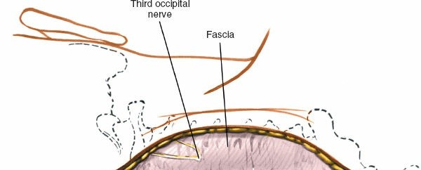
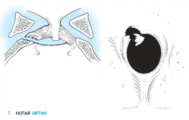
Fig 1. Important anterior and posterior supporting structures of the cervical spine. Understanding the integrity of the anterior longitudinal ligament, annulus fibrosus, and posterior ligamentous complex is paramount.
Mechanistic Classification of Lower Cervical Spine Injuries
While numerous classifications of cervical spine injuries have been formulated over the decades, the mechanistic classification proposed by Allen et al. remains one of the most comprehensive and clinically useful frameworks. Based on a rigorous review of 165 lower cervical spine injuries, Allen and colleagues identified six common patterns of injury. Each pattern is subdivided into progressive stages based on the severity of failure in the osseous and ligamentous structures.
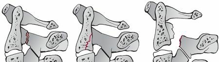
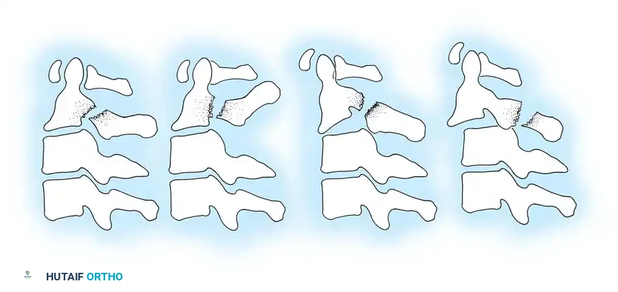
Compressive Flexion (Five Stages)
This injury pattern typically results from a force applied to the anterior cranium while the neck is in flexion.
* Stage 1: Blunting of the anterosuperior vertebral margin to a rounded contour. There is no evidence of failure of the posterior ligamentous complex (PLC).
* Stage 2: In addition to Stage 1 changes, there is obliquity of the anterior vertebral body with loss of anterior centrum height. The anteroinferior vertebral body develops a "beak" appearance, and a vertical fracture may be present.
* Stage 3: Features of Stage 2 plus a fracture line passing obliquely from the anterior surface through the centrum and extending through the inferior subchondral plate. The anterior "beak" is fractured.
* Stage 4: Deformation of the centrum and fracture of the beak with mild (< 3 mm) displacement of the inferoposterior vertebral margin into the spinal canal.
* Stage 5: Severe bony comminution with > 3 mm of posterior displacement of the vertebral body into the spinal canal. The vertebral arch remains intact, but the articular facets are separated, and the interspinous space is widened, indicating a catastrophic posterior ligamentous disruption in tension.
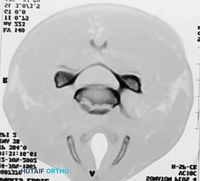
Vertical Compression (Three Stages)
Resulting from pure axial loading, often seen in shallow-water diving accidents.
* Stage 1: Fracture of the superior or inferior end plate with a central "cupping" deformity. The PLC remains intact.
* Stage 2: Fracture of both vertebral end plates with cupping deformities. Minimal displacement is observed despite centrum fracture lines.
* Stage 3: Severe fragmentation of the centrum with peripheral displacement in multiple directions (burst fracture). The posterior aspect of the vertebral body is often retropulsed into the spinal canal. The PLC may fail depending on the degree of comminution.
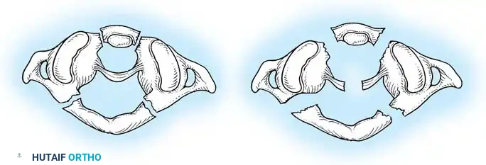
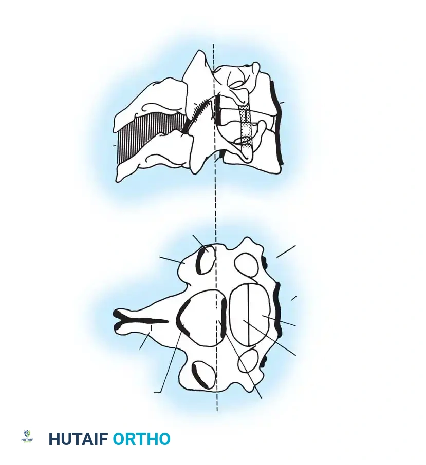
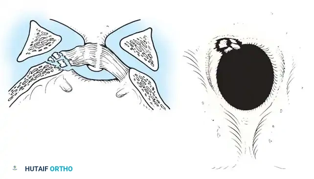
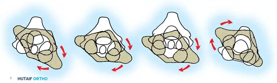
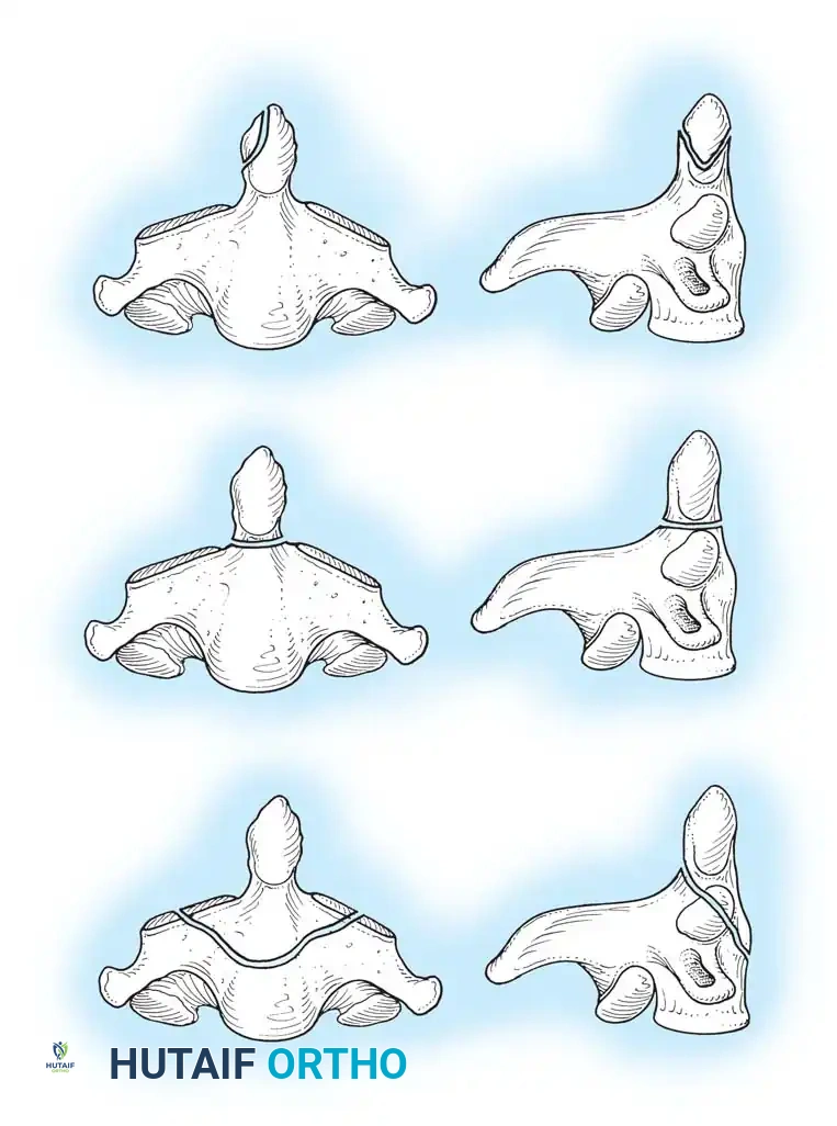
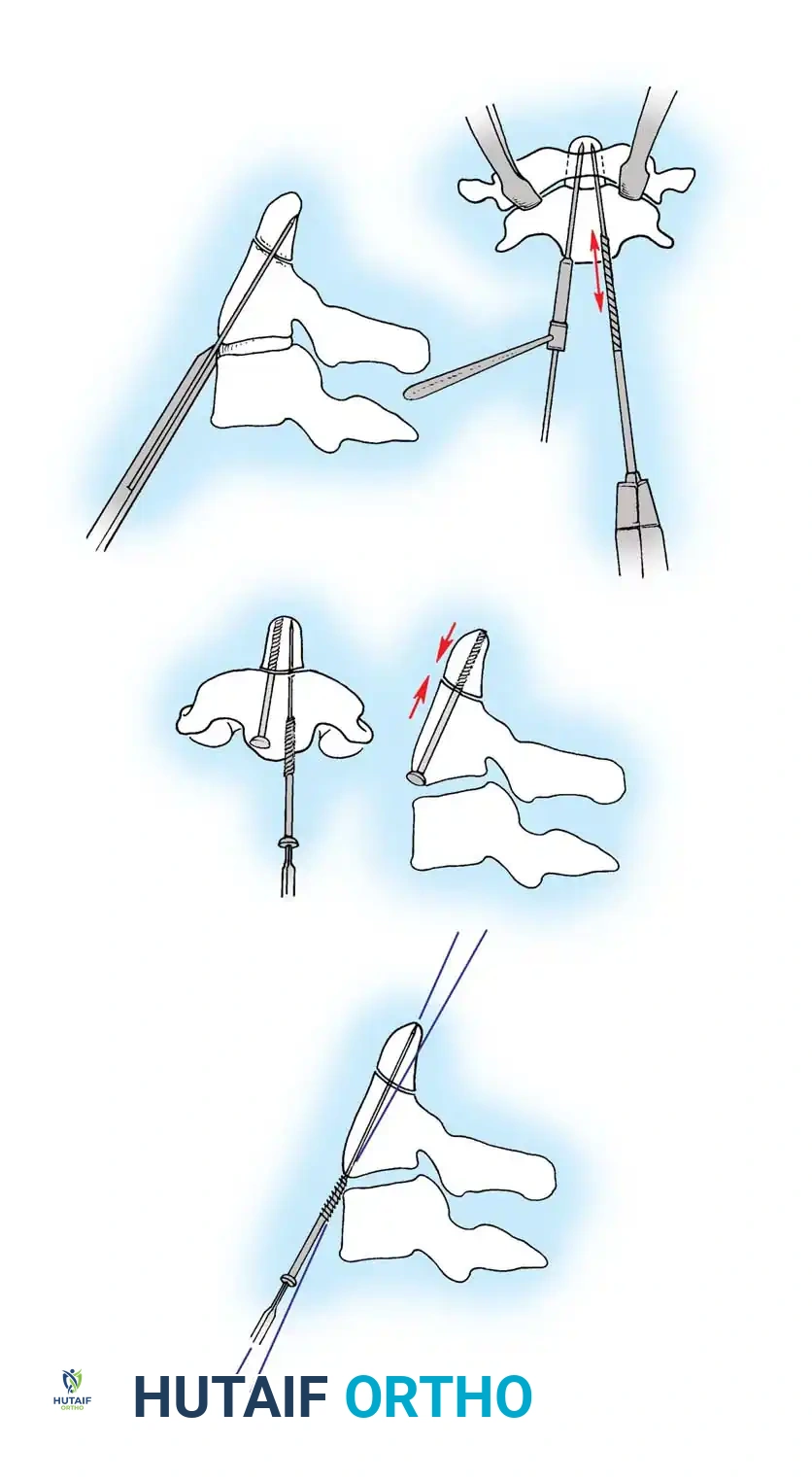
Fig 2. Diagrammatic representation of facet subluxation and dislocation mechanics.
Distractive Flexion (Four Stages)
Characterized by an axis of flexion anterior to the vertebral body, placing the posterior elements under extreme tension.
* Stage 1: Failure of the PLC, evidenced by facet subluxation in flexion and abnormal divergence of the spinous processes (widened interspinous distance).
* Stage 2: Unilateral facet dislocation. Subluxation of the contralateral facet suggests severe ligamentous injury. Beatson's serial sectioning studies demonstrated that unilateral dislocation can occur with rupture of only the posterior interspinous ligament and the facet capsule.
* Stage 3: Bilateral facet dislocations, presenting with approximately 50% anterior subluxation of the vertebral body. This requires complete rupture of the interspinous ligament, both facet capsules, the posterior longitudinal ligament (PLL), and the annulus fibrosus.
* Stage 4: Full vertebral body width displacement anteriorly. This creates a grossly unstable motion segment, often termed a "floating" vertebra.
Compressive Extension (Five Stages)
Resulting from a posterior-to-anterior force vector with the neck extended.
* Stage 1: Unilateral vertebral arch fracture with or without anterior rotatory displacement. May present as a "transverse facet" on AP radiographs.
* Stage 2: Bilaminar fractures without other tissue failure, typically occurring at multiple contiguous levels.
* Stage 3: Bilateral vertebral arch fractures (articular processes, pedicles, or lamina) without vertebral body displacement.
* Stage 4: Bilateral vertebral arch fractures with partial anterior displacement of the vertebral body.
* Stage 5: Bilateral vertebral arch fracture with full vertebral body width displacement anteriorly. The posterior arch remains behind, while the centrum shears off the anterosuperior portion of the vertebra below.
Distractive Extension (Two Stages)
- Stage 1: Failure of the anterior ligamentous complex (ALL) or a transverse fracture of the centrum. Radiographically identified by abnormal widening of the anterior disc space.
- Stage 2: Failure of the PLC with posterior displacement of the upper vertebral body into the spinal canal.
Clinical Pearl: Distractive extension injuries often reduce spontaneously when the patient is placed supine in a neutral position. Radiographic evidence of displacement may be deceptively minimal (rarely > 3 mm) on initial trauma bay films. High clinical suspicion and MRI are essential.
Lateral Flexion (Two Stages)
- Stage 1: Asymmetrical compression fracture of the centrum and ipsilateral vertebral arch fracture, without displacement.
- Stage 2: Lateral asymmetrical compression with either an ipsilateral displaced arch fracture or contralateral ligamentous failure with facet separation.
Biomechanics of Clinical Instability
Determining clinical instability is the cornerstone of cervical spine trauma management. White, Southwick, and Panjabi defined clinical instability as the loss of the spine's ability to maintain its patterns of displacement under physiological loads, preventing initial or additional neurological deficit, major deformity, or incapacitating pain.
They developed a rigorous checklist for the diagnosis of clinical instability in the lower cervical spine. A total score of 5 or more indicates definitive instability requiring surgical stabilization.
Checklist for Diagnosis of Clinical Instability (White & Panjabi):
* Anterior elements destroyed or unable to function: 2 points
* Posterior elements destroyed or unable to function: 2 points
* Relative sagittal plane translation > 3.5 mm: 2 points
* Relative sagittal plane rotation > 11 degrees: 2 points
* Positive stretch test: 2 points
* Medullary (cord) damage: 2 points
* Root damage: 1 point
* Abnormal disc narrowing: 1 point
* Dangerous loading anticipated: 1 point
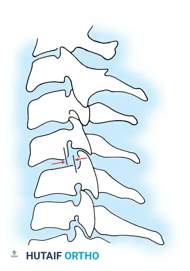
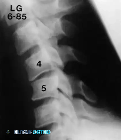
Fig 3. Sagittal plane translation of more than 3.5 mm suggests clinical instability.
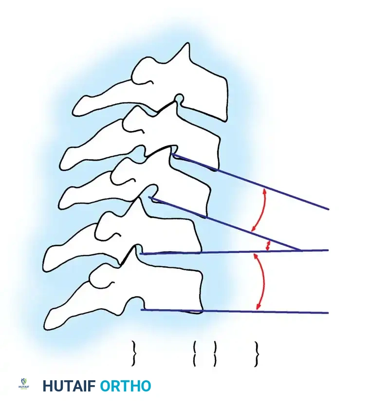
Fig 4. Sagittal plane rotation. An angular difference of more than 11 degrees between adjacent segments is a definitive marker of instability.
Diagnostic Modalities and The Stretch Test
While modern trauma protocols rely heavily on high-resolution CT and MRI, the Stretch Test remains a classical biomechanical tool for determining clinical instability in the lower cervical spine when advanced imaging is unavailable or equivocal.
Surgical Warning: The stretch test is strictly contraindicated in an obviously unstable injury. It must always be performed under the direct, continuous supervision of the attending orthopedic or neurosurgical consultant.
🔪 Surgical Technique 35-1: The Stretch Test Protocol
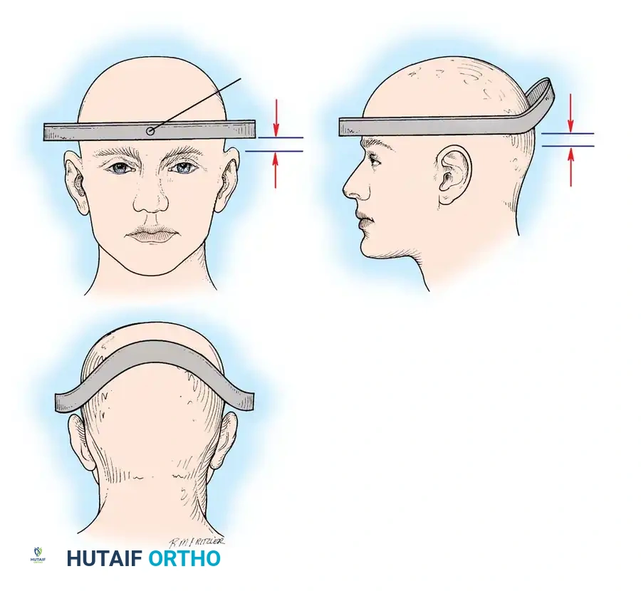
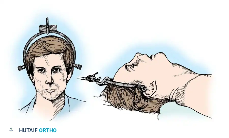
- Preparation: Apply traction through secured cranial skeletal traction (Gardner-Wells tongs). A head halter is inadequate for the weights required and risks skin necrosis. Place a rolled towel under the patient’s neck to maintain a neutral lordotic contour.
- Baseline Imaging: Place the radiographic film/detector as close to the neck as possible. Position the X-ray tube 72 inches away to minimize magnification, and obtain a baseline lateral radiograph.
- Incremental Loading: Begin with 10 lb of traction. Increase the weight in 5-lb increments.
- Monitoring: After each 5-lb addition, perform a strict neurological examination and obtain a repeat lateral radiograph.
- Viscoelastic Creep: Allow at least 5 minutes between incremental weight applications to account for the viscoelastic creep of the disrupted ligamentous structures.
- Endpoints: Continue until one of the following endpoints is reached:
- One-third of the patient's body weight is applied.
- A maximum of 65 lb is reached.
- Positive Test (STOP IMMEDIATELY): Any neurological deterioration occurs, interspace separation exceeds 1.7 mm, or the angular difference between the prestretched and loaded condition exceeds 7.5 degrees.
Principles of Treatment and Closed Reduction
The overarching goals of treating cervical spine injuries are:
1. Realign the spinal column.
2. Prevent loss of function in undamaged neurological tissue.
3. Optimize the biological environment for neurological recovery.
4. Obtain and maintain rigid spinal stability.
5. Facilitate early functional rehabilitation.
Closed Reduction via Skeletal Traction
After initial ATLS medical stabilization, spinal alignment is typically attempted via closed skeletal traction using spring-loaded Gardner-Wells tongs or a halo ring.
Traction Protocol:
* Apply an initial 10 lbs of weight to counteract the weight of the head.
* Add 5 lbs for each level of injury (e.g., a C5-C6 dislocation would require roughly 10 lbs + (5 levels × 5 lbs) = 35 lbs).
* Add weight in 5-lb increments with continuous clinical and radiographic monitoring.
* Maximum safe limits are generally considered to be 40 to 50 lbs, though some rigid dislocations may require more under strict fluoroscopic guidance.
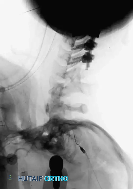
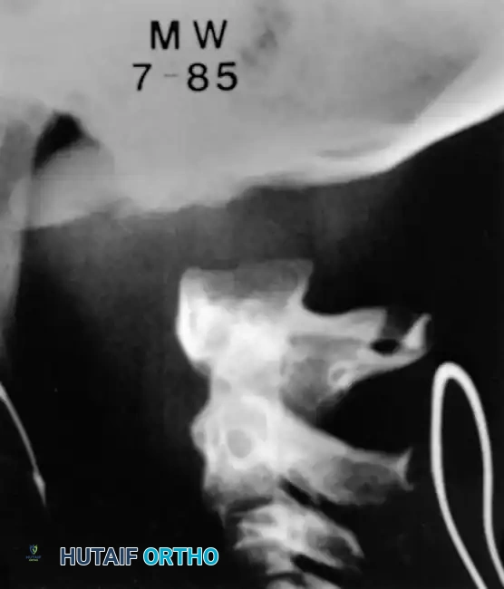
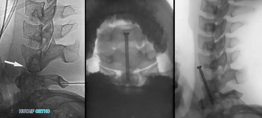
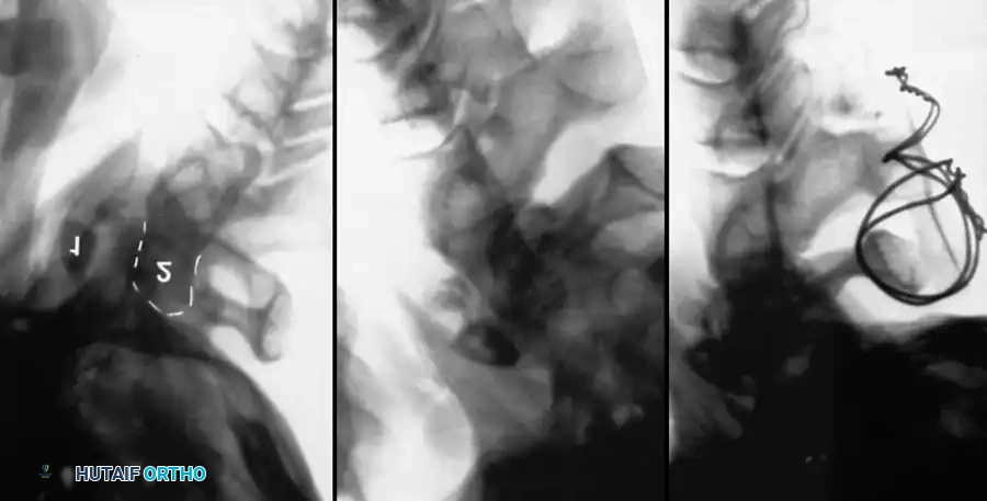
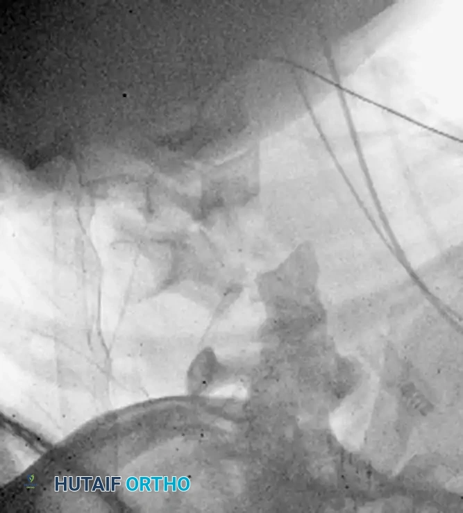
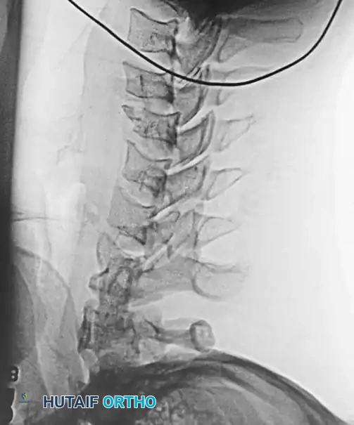
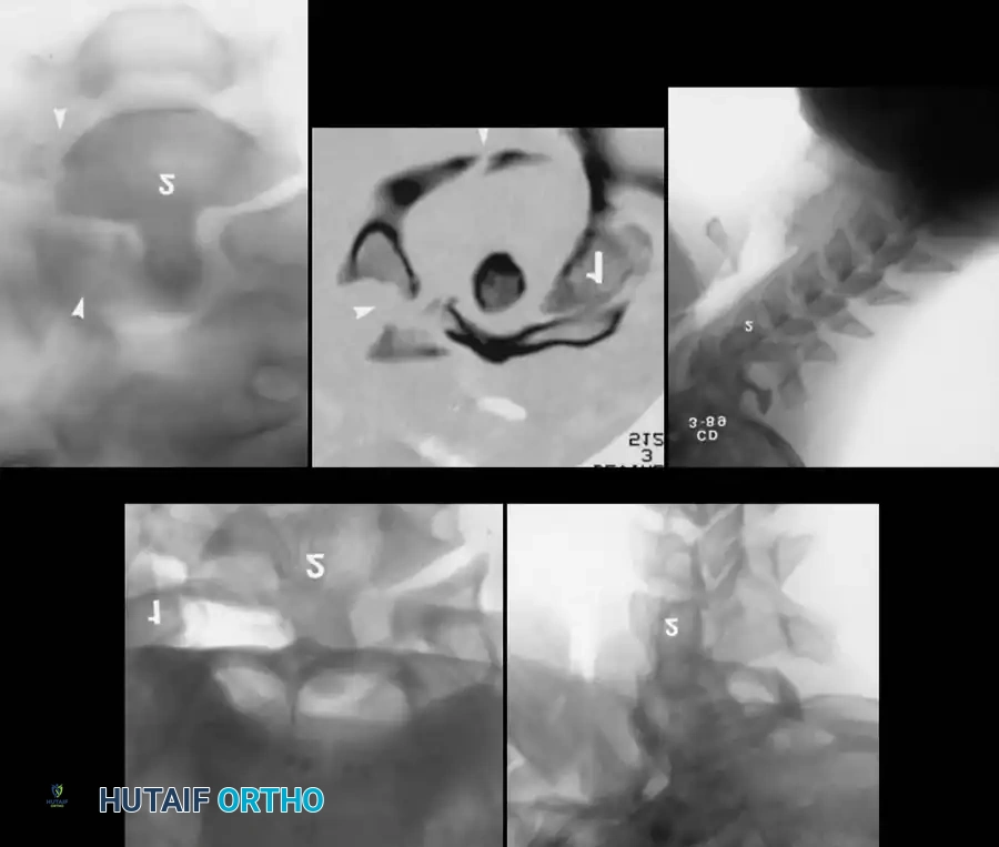
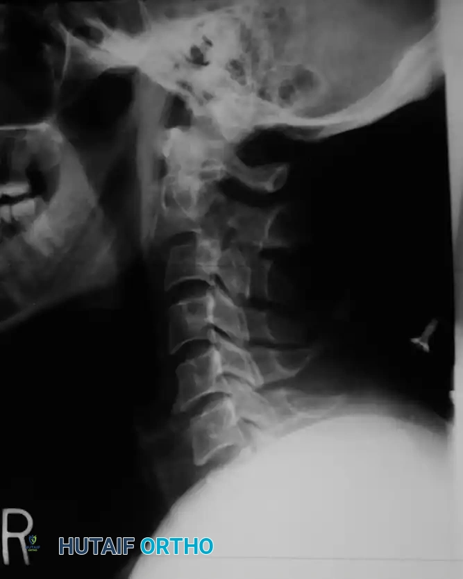
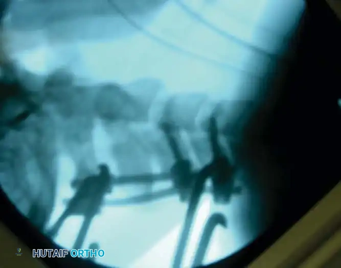
Fig 5. Lateral radiograph demonstrating the application of cranial skeletal traction for the reduction of a cervical dislocation.
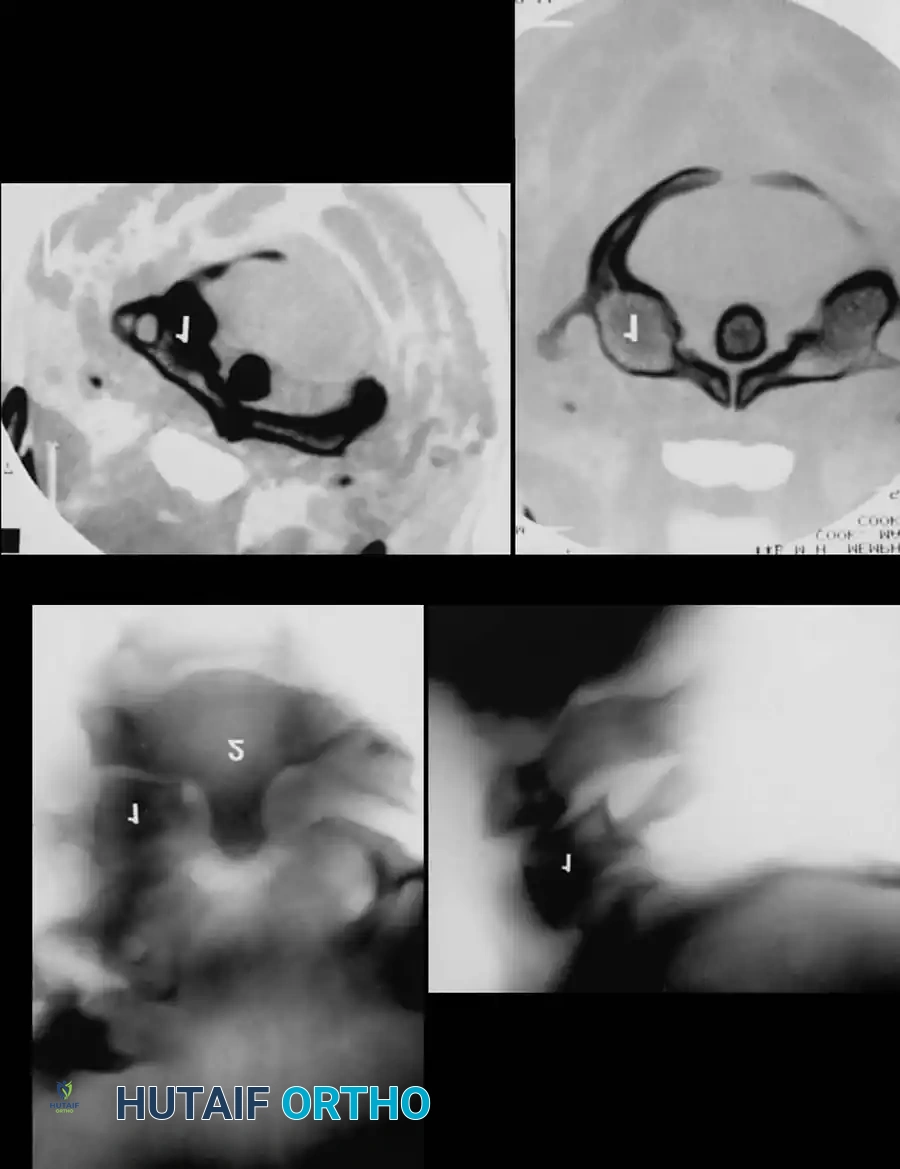
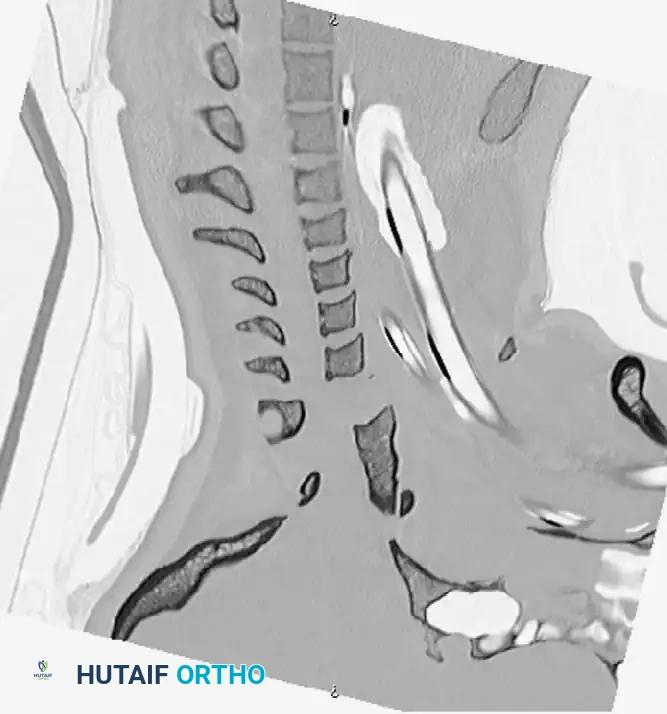
The Pre-Reduction MRI Debate
A critical decision in the trauma bay is whether to obtain an MRI prior to closed reduction. Arena, Eismont, and Green reported that nearly 9% of patients with cervical facet dislocations have a concomitant extruded cervical disc. Reducing a facet dislocation with an extruded disc behind the intact PLL can theoretically drag the disc material into the spinal canal, causing an iatrogenic spinal cord injury.
However, Vaccaro et al. established the current standard of care: It is unnecessary to delay reduction for an MRI in an alert, cooperative patient who can participate in a reliable clinical neurological examination during the reduction process. If the patient is obtunded, intoxicated, or otherwise unexaminable, a pre-reduction MRI is mandatory to rule out a compressive anterior disc herniation before any traction is applied.
Surgical Management: Approaches and Techniques
If closed reduction fails, or if the injury pattern is inherently unstable (e.g., bilateral facet dislocation, burst fracture with cord compression), operative intervention is indicated.
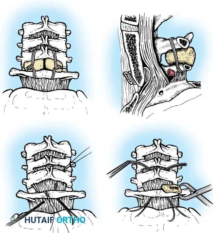
Anterior Cervical Discectomy and Fusion (ACDF)
Indications: Anterior column compromise, extruded traumatic disc herniations, or as the first stage in a 360-degree fusion for severe distractive flexion injuries.
Positioning & Approach:
* The patient is positioned supine on a radiolucent Jackson table.
* The neck is maintained in neutral alignment using Gardner-Wells tongs with 5-10 lbs of maintenance traction.
* A standard Smith-Robinson transverse incision is made, typically left-sided to avoid the recurrent laryngeal nerve (which has a more predictable course on the left).
* The avascular plane between the visceral axis (trachea/esophagus) medially and the carotid sheath laterally is developed.
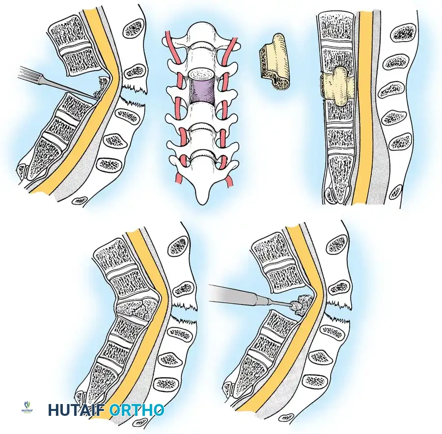
Surgical Steps:
1. Exposure: Retract the longus colli muscles laterally to expose the anterior vertebral bodies and the damaged disc space.
2. Discectomy: Perform a complete discectomy using curettes and pituitary rongeurs. In trauma, the PLL is often torn; carefully remove any extruded disc fragments compressing the cord.
3. Endplate Preparation: Decorticate the cartilaginous endplates using a high-speed burr to expose bleeding subchondral bone, ensuring a robust fusion bed.
4. Grafting: Insert a structural allograft or PEEK cage packed with autograft/demineralized bone matrix (DBM) into the disc space.
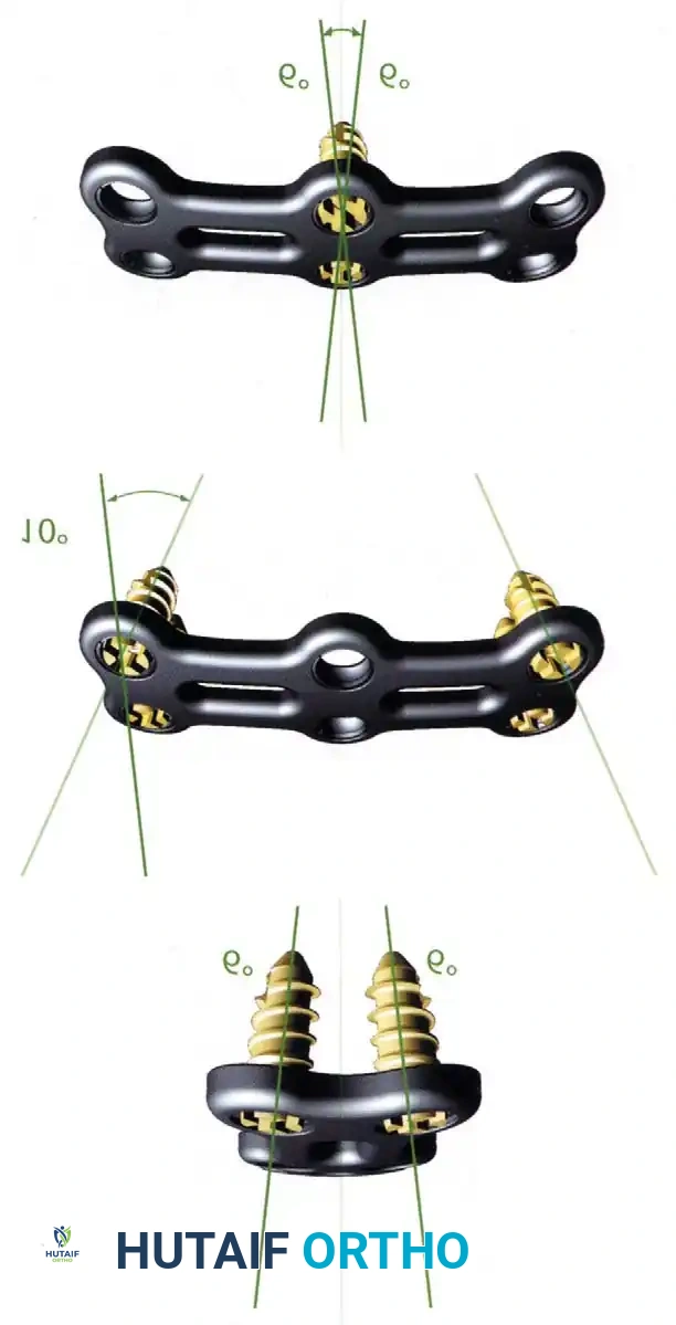
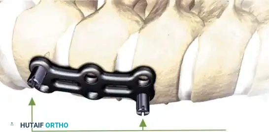
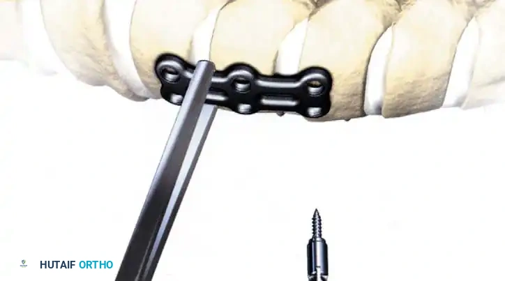
5. Plating: Apply a rigid anterior cervical plate. Ensure screws are placed parallel to the endplates and do not breach the adjacent disc spaces.
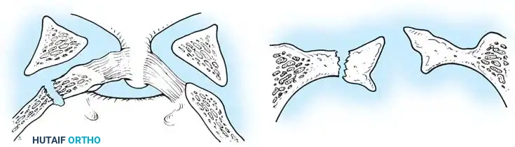
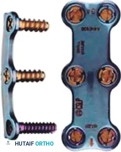
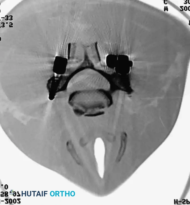
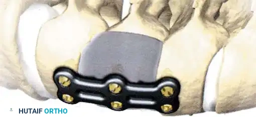
Fig 6. Anterior cervical plating construct providing rigid stabilization of the anterior column.
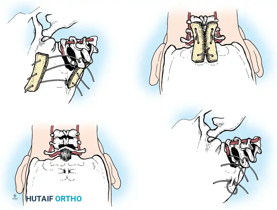
Posterior Cervical Fusion (PCF) and Instrumentation
Indications: Posterior tension band failure, irreducible facet dislocations requiring open reduction, or multi-level instability.
Positioning & Approach:
* The patient is carefully log-rolled prone onto a Jackson table. The head is secured in a Mayfield pin fixator.
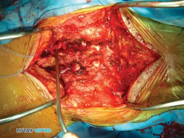
* A midline posterior incision is made, utilizing the avascular ligamentum nuchae plane to expose the spinous processes, laminae, and lateral masses out to the medial border of the facet joints.
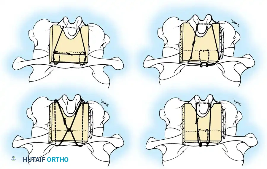
Surgical Steps:
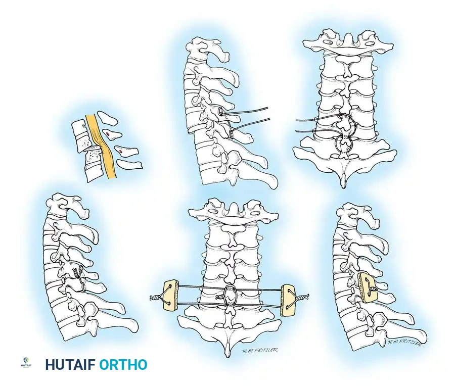
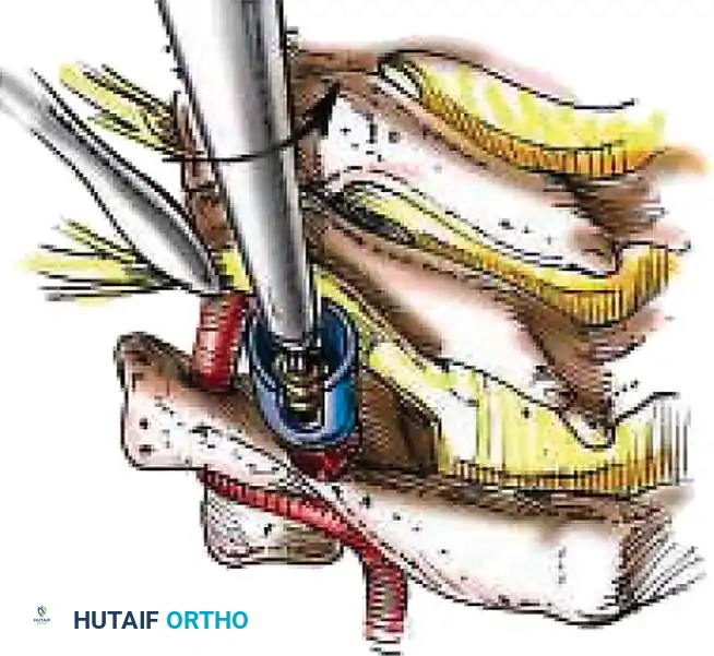
1. Open Reduction: If a facet is dislocated, carefully lever the inferior articular process of the superior vertebra over the superior articular process of the inferior vertebra using a Penfield elevator.
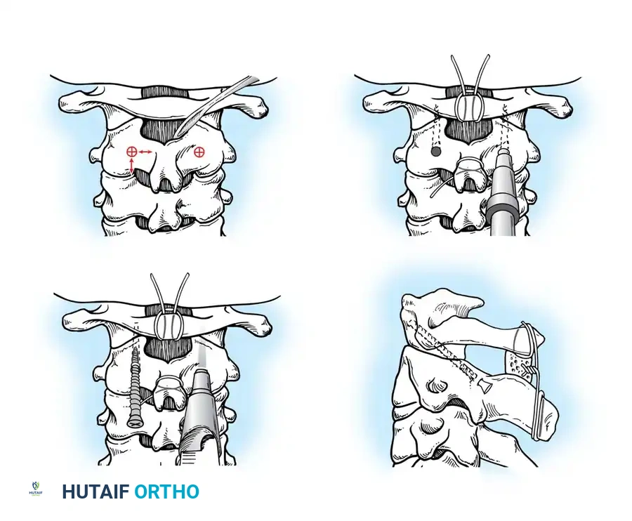
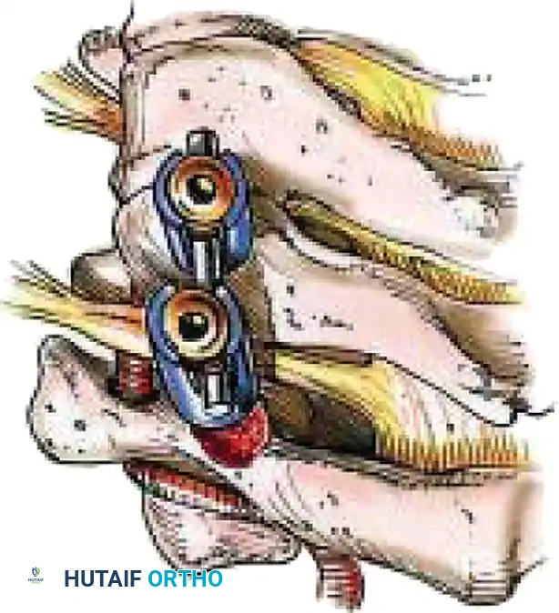
2. Lateral Mass Screw Fixation:
* Utilize the Magerl or Roy-Camille trajectory.
* Magerl Technique: The entry point is 1 mm medial and 1 mm superior to the center of the lateral mass. The drill is angled 25 degrees laterally (to avoid the vertebral artery) and 15 degrees cephalad (to avoid the exiting nerve root).
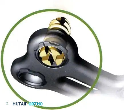
3. Rod Contouring: Contour titanium or cobalt-chrome rods to match the patient's natural cervical lordosis and secure them to the screw heads with set screws.
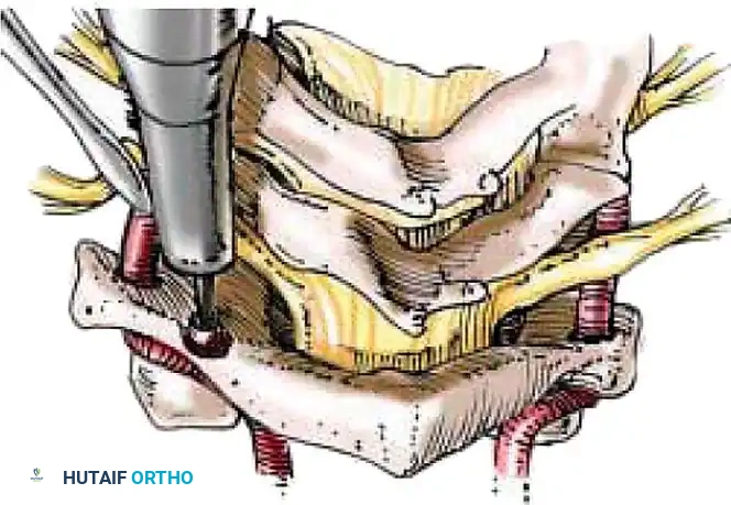
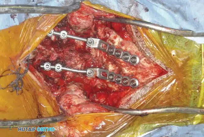
4. Decortication and Fusion: Aggressively decorticate the lateral masses and facet joints with a high-speed burr. Pack the gutters with cancellous autograft (often harvested from the iliac crest) or high-quality allograft.
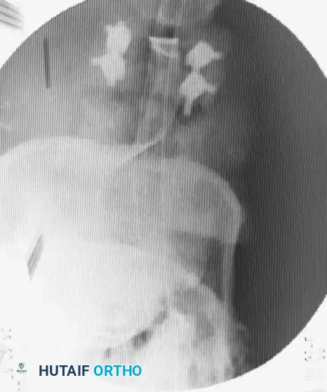
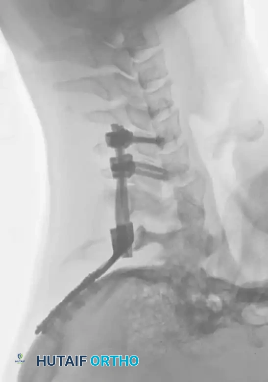
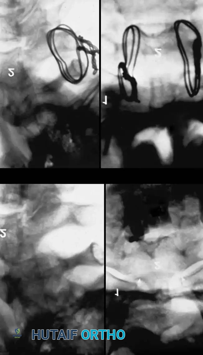
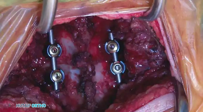
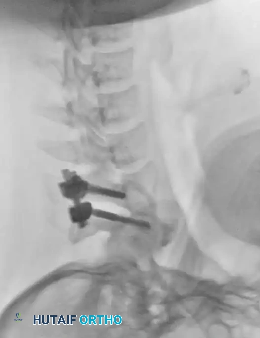
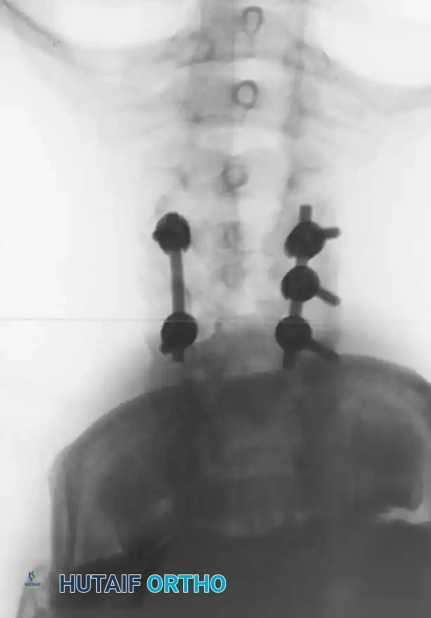
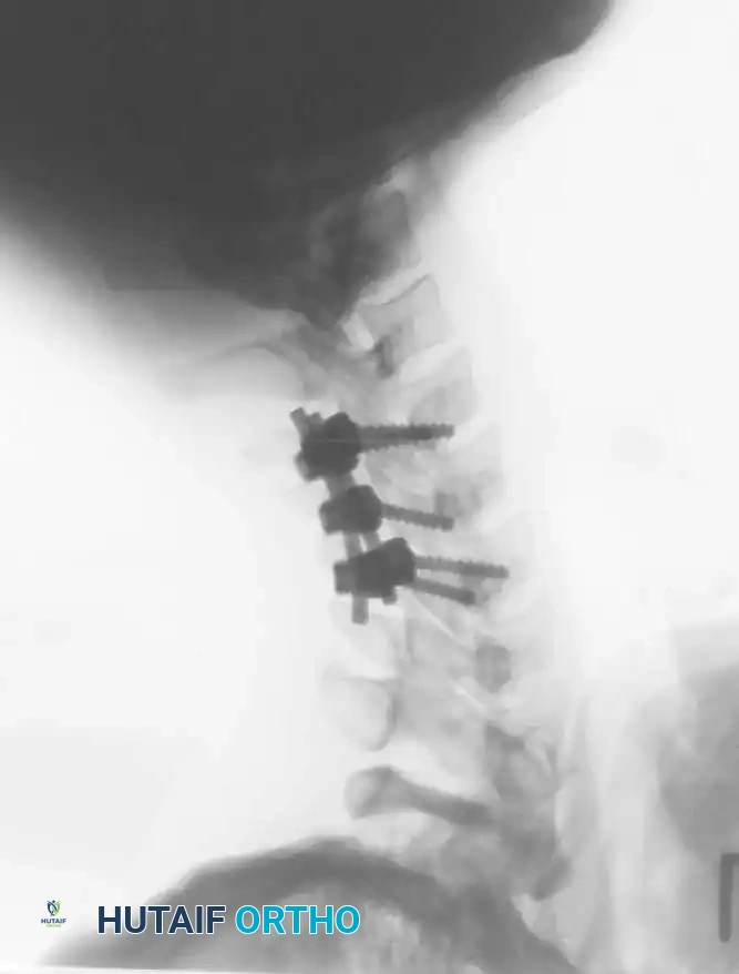
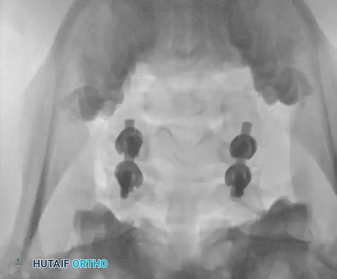
Fig 7. Posterior cervical lateral mass screw and rod construct, providing excellent biomechanical stability for posterior tension band failures.
Postoperative Protocols and Rehabilitation
Meticulous postoperative care is vital to ensure construct survival and neurological recovery.
- Immobilization: Patients are typically placed in a rigid cervical orthosis (e.g., Aspen or Miami J collar) for 6 to 12 weeks postoperatively, depending on bone quality and the rigidity of the internal fixation.
- Hemodynamic Management: For patients with spinal cord injuries, Mean Arterial Pressure (MAP) should be maintained strictly > 85 mmHg for 7 days post-injury to ensure adequate perfusion to the spinal cord penumbra.
- Radiographic Follow-up: Upright AP and lateral radiographs are obtained prior to discharge, at 2 weeks, 6 weeks, 3 months, and 6 months to monitor for hardware failure, loss of alignment, and progression of arthrodesis.
- Rehabilitation: Early mobilization is encouraged. Physical therapy focuses on isometric neck strengthening and proprioceptive recovery once radiographic fusion is confirmed.
Clinical Pearl: Always maintain a high index of suspicion for adjacent segment disease in the years following a rigid cervical fusion. Educate the patient on the biomechanical stresses transferred to the unfused levels above and below the construct.
===```
Associated Surgical & Radiographic Imaging
📚 Medical References
- cervical spine injuries in children, Clin Orthop Relat Res 129:172, 1977.
- Hensinger RN: Fractures of the spine: II. Fractures of the thoracic and lumbar spine. In Rockwood CA Jr, Wilkins KE, King RE, eds: Fractures in children, Philadelphia, 1984, Lippincott. Herzenberg JE, Hensinger RN, Dedrick DK, et al: Emergency transport and position of young children who have an injury of the cervical spine: the standard backboard may be hazardous, J Bone Joint Surg 71A:15, 1989.
- Horal J, Nachemson A, Scheller S: Clinical and radiological longterm follow-up of vertebral fractures in children, Acta Orthop Scand 43:491, 1972.
- Jones ET, Hensinger RN: Spinal deformity in idiopathic juvenile osteoporosis, Spine 6:1, 1981.
- Keller RH: Traumatic displacement of the cartilaginous vertebral rim: a sign of intervertebral disc prolapse, Radiology 110:21, 1974.
- Kewalramani LS, Tori JA: Spinal cord trauma in children: neurologic patterns, radiologic features, and pathomechanics of injury, Spine 5:11, 1980.
- Lowrey JJ: Dislocated lumbar vertebral epiphysis in adolescent children: report of three cases, J Neurosurg 38:232, 1973.
- Marar BC, Balachandran N: Non-traumatic atlanto-axial dislocation in children, Clin Orthop Relat Res 92:220, 1973.
- Odent T, Langlais J, Glorion C, et al: Fractures of the odontoid process: a report of 15 cases in children younger than 6 years, J Pediatr Orthop 19:51, 1999.
- Parke WW, Schiff DCM: The applied anatomy of the intervertebral disc, Orthop Clin North Am 2:309, 1971.
- Reid AB, Letts RM, Black GB: Pediatric Chance fractures: association with intra-abdominal injuries and seat belt use, J Trauma 30:384, 1990.
- Rumball K, Jarvis J: Seat-belt injuries of the spine in young children, J Bone Joint Surg 74B:571, 1992.
- Scheuermann HW: The classic kyphosis dorsalis juvenilis, Z Orthop Chir 41:305, 1921.
- Schiff DCM, Parke WW: The arterial blood supply of the odontoid process (dens), Anat Rec 172:399, 1972.
- Sherk HH, Nicholson JT, Chung SMK: Fractures of the odontoid process in young children, J Bone Joint Surg 60A:921, 1978.
- Sherk HH, Schut L, Lane J: Fractures and dislocations of the cervical spine in children, Orthop Clin North Am 7:593, 1976.
- Wiltse LL, Newman PH, Macnab I: Classifi cation of spondylolysis and
You Might Also Like