Mastering Orthopedic Deformity Correction: Frontal Plane Axis Planning & Paley Principles
Key Takeaway
Frontal plane deformity correction planning uses Paley principles. It involves analyzing mechanical and anatomic axes, calculating Mechanical Axis Deviation (MAD), and measuring joint orientation angles. This identifies the Center of Rotation of Angulation (CORA) for precise osteotomy planning.
Introduction to Deformity Correction and Axis Planning
In the modern era of orthopedic surgery, the correction of complex limb deformities has completely evolved from a subjective art of eyeballing clinical alignment into a rigorous mathematically driven science. For decades, surgeons relied on intraoperative intuition, which frequently resulted in malalignment, iatrogenic translation, and altered joint biomechanics. At the heart of the modern orthopedic revolution are the foundational principles popularized by Dr Dror Paley. His systematic reproducible methodology for analyzing and correcting bone deformities has become the gold standard worldwide. The absolute foundational pillar of this methodology is Frontal Plane Mechanical and Anatomic Axis Planning.
An angular deformity of the femur or tibia is never merely a cosmetic curvature of the bone. It represents a profound destructive disruption of the biomechanical axes that dictate load bearing across the hip, knee, and ankle joints. When a bone is angulated, its weight bearing axes are fundamentally altered. This shift in the mechanical axis deviation dramatically alters the contact stresses on articular cartilage. Over time, even a few degrees of uncorrected angulation can lead to catastrophic premature osteoarthritis, ligamentous strain, and functional debilitating pain.
Understanding how to mathematically dissect a deformed bone into its constituent proximal and distal segments, identify the exact point of angulation, and plan a precise osteotomy is the hallmark of a master deformity surgeon. This comprehensive high yield masterclass will deconstruct Paley principles, transforming the dense biomechanical concepts of the Center of Rotation of Angulation, Mechanical Axis Deviation, and joint orientation angles into an actionable exhaustive framework for surgeons in training.
Biomechanical Foundation Mechanical vs Anatomic Axes
To truly understand and correct an angular deformity, one must first achieve absolute mastery over the normal biomechanical state of the human lower limb. The concept of deformity planning is easiest to grasp if you visualize a perfectly straight healthy bone, and then mentally produce an angular break in it. When a bone is divided and angulated, the single continuous axis of that bone is also divided into two distinct diverging segments the proximal axis and the distal axis.
Orthopedic axis planning relies on two distinct types of lines Anatomic and Mechanical. Conflating the two is a common pitfall for junior surgeons. Mastery of these axes is the prerequisite for all subsequent deformity analysis.
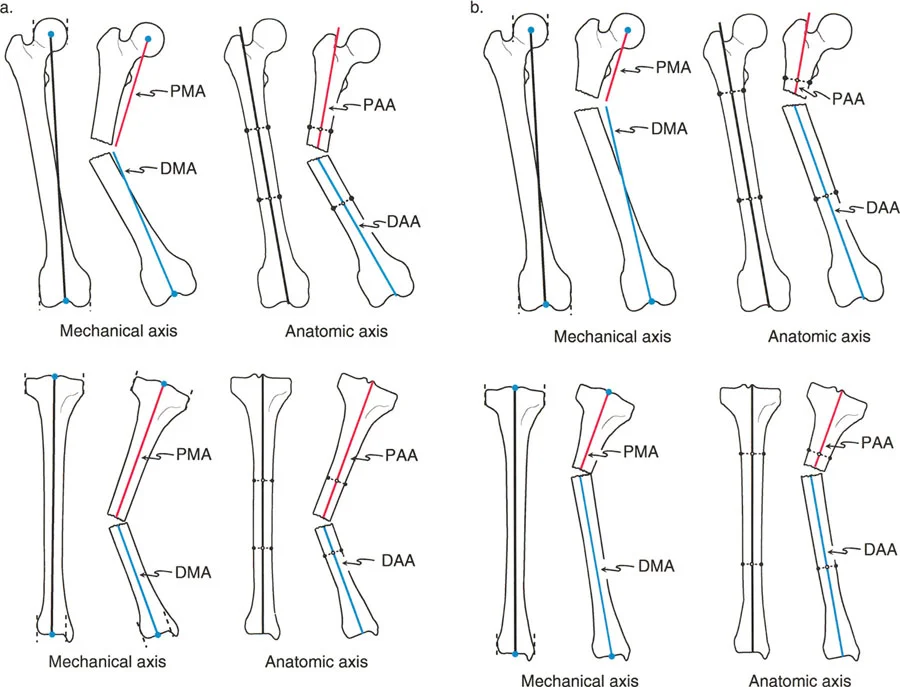
The Anatomic Axis
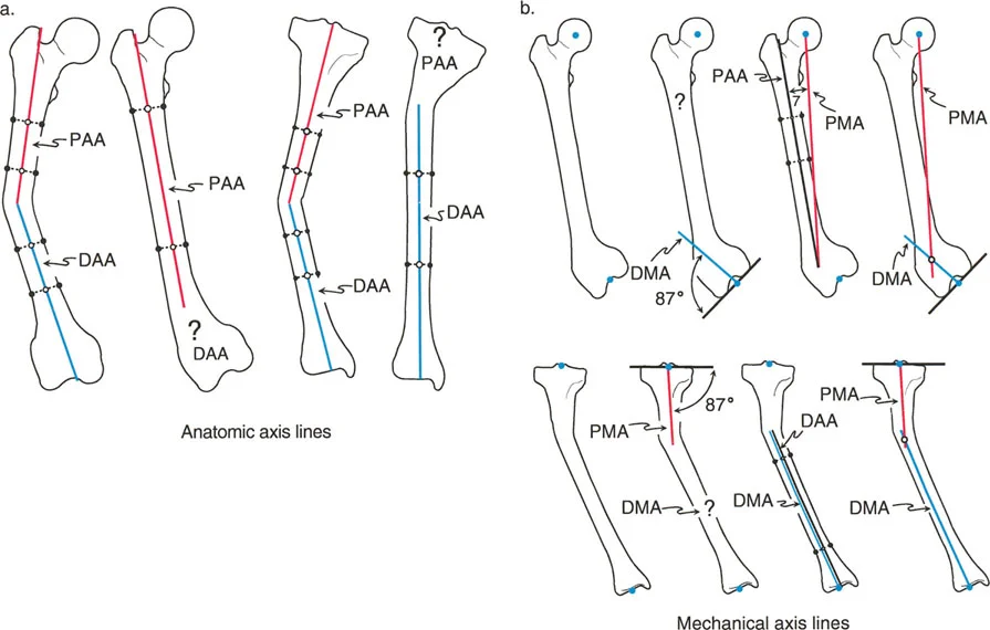
The anatomic axis is defined by the physical anatomy of the bone itself specifically the mid diaphyseal line. In a normal straight bone, a line drawn directly through the center of the medullary canal from the proximal to the distal end represents the anatomic axis. It is the line around which intramedullary nails are designed.
In the Tibia the anatomic axis runs straight down the dead center of the tibial shaft.
In the Femur the anatomic axis runs down the center of the femoral shaft. However, because of the anatomical offset of the femoral head and neck, the anatomic axis of the femur does not pass through the center of the hip joint. It exits proximally at the tip of the greater trochanter or piriformis fossa depending on proximal morphology.
When a diaphyseal deformity occurs, this single anatomic axis is broken into a Proximal Anatomic Axis and a Distal Anatomic Axis. In cases of pure diaphyseal deformity, drawing these lines is straightforward simply connect the mid diaphyseal points of the proximal segment and the mid diaphyseal points of the distal segment.
The Mechanical Axis
The mechanical axis conversely is not defined by the medullary canal. It is a true invisible biomechanical load bearing line that dictates how gravity and ground reaction forces pass through the limb. It strictly connects the center points of the joints.
In the Overall Lower Extremity the mechanical axis of the entire lower limb runs from the center of the femoral head to the center of the ankle joint the tibial plafond. In a perfectly aligned normal limb, this line passes precisely through the center of the knee joint.
In the Femur the mechanical axis connects the center of the femoral head to the center of the knee joint.
In the Tibia the mechanical axis connects the center of the knee joint to the center of the ankle joint.
Because the mechanical and anatomic axes of the tibia are nearly perfectly parallel and are universally considered collinear for surgical planning purposes, the Proximal Anatomic Axis and Proximal Mechanical Axis of the tibia are essentially the exact same line.
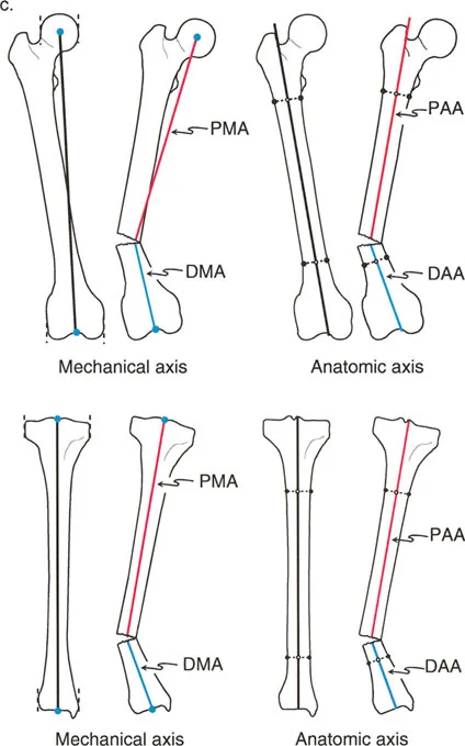
However, in the frontal plane of the femur, the mechanical and anatomic axes diverge by approximately 7 degrees. Therefore, the femoral Proximal Mechanical Axis and Proximal Anatomic Axis are distinctly different lines, as are the distal equivalents. Recognizing this divergence is critical when planning distal femoral osteotomies.
Understanding Mechanical Axis Deviation
Before analyzing individual bones, the surgeon must evaluate the entire limb to determine if a deformity exists and how it affects overall load bearing. This is accomplished by calculating the Mechanical Axis Deviation.
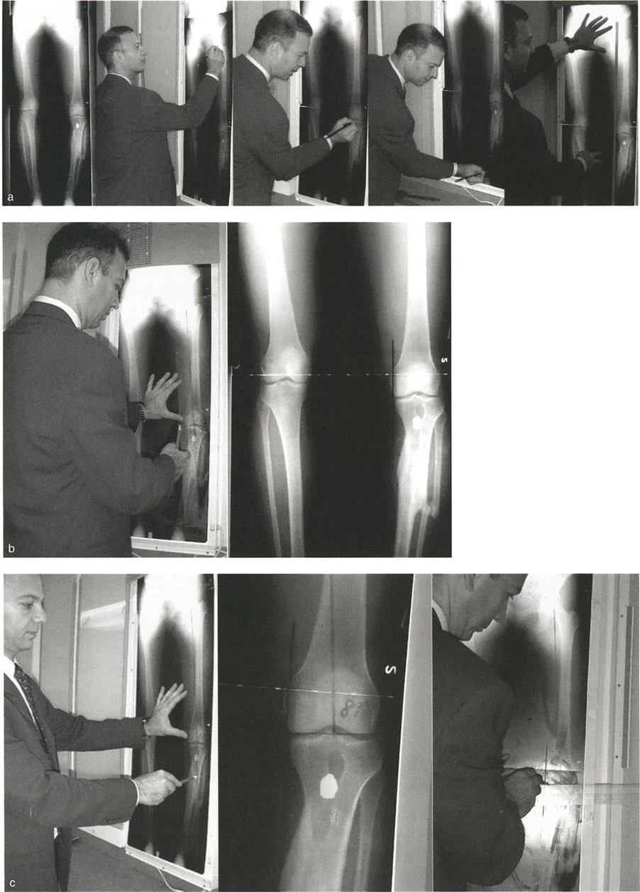
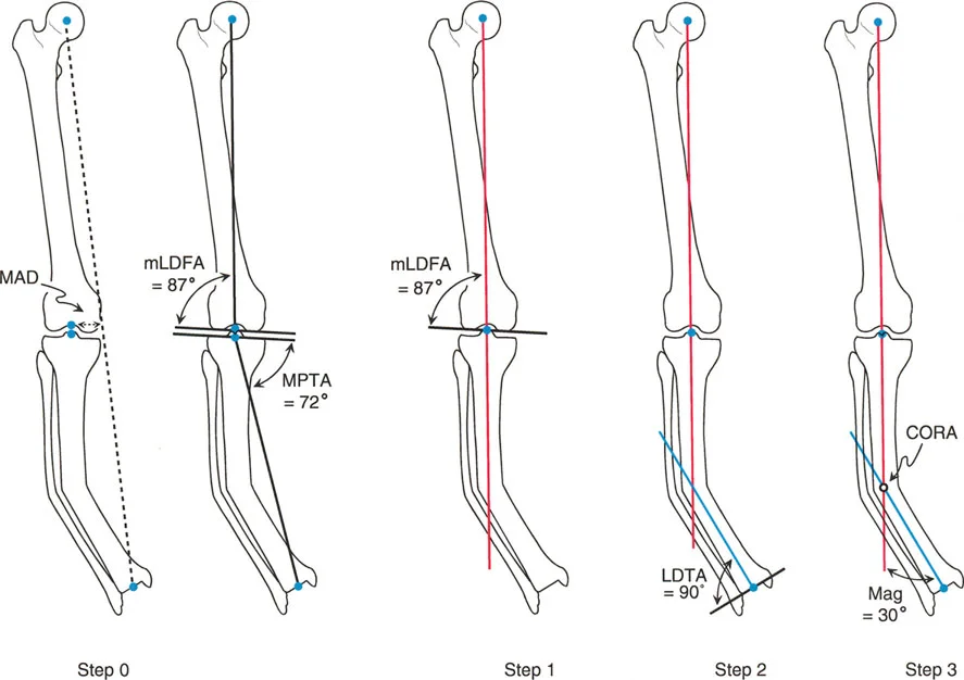
The Malalignment Test is the first step in any deformity evaluation. On a standing 51 inch full length radiograph with the patella facing strictly forward, a line is drawn from the center of the femoral head to the center of the ankle joint. This is the mechanical axis of the lower extremity.
In a normal limb, this line passes slightly medial to the exact center of the knee joint, typically 8 to 10 millimeters medial to the midline of the tibial plateau.
If the mechanical axis line falls significantly medial to the center of the knee, the patient has a varus deformity, and the medial compartment is experiencing pathological overload.
If the mechanical axis line falls lateral to the center of the knee, the patient has a valgus deformity, resulting in lateral compartment overload.
The distance measured in millimeters from the center of the knee joint to the mechanical axis line is the Mechanical Axis Deviation. Quantifying the Mechanical Axis Deviation is essential because the ultimate goal of any deformity correction surgery is to restore the Mechanical Axis Deviation to a normal physiological range, thereby normalizing joint contact stresses.
Standard Joint Orientation Angles
Once Malalignment is confirmed via an abnormal Mechanical Axis Deviation, the surgeon must perform the Malorientation Test to localize the source of the deformity. Is the varus or valgus originating in the femur, the tibia, or the knee joint itself?
To answer this, we utilize Joint Orientation Angles. These are the angles formed by the intersection of the mechanical or anatomic axes with the joint lines. Joint lines are drawn across the articular surfaces of the hip, knee, and ankle.
By measuring these angles and comparing them to established population norms, the surgeon can pinpoint the exact segment of bone responsible for the mechanical axis shift.
Normal Frontal Plane Joint Parameters
The following table summarizes the standard normal values for frontal plane mechanical joint orientation angles based on Paley principles. Memorizing these values is non negotiable for the deformity surgeon.
| Angle Acronym | Full Name | Normal Value | Range |
|---|---|---|---|
| mLPFA | Mechanical Lateral Proximal Femoral Angle | 90 degrees | 85 to 95 degrees |
| mLDFA | Mechanical Lateral Distal Femoral Angle | 88 degrees | 85 to 90 degrees |
| MPTA | Medial Proximal Tibial Angle | 87 degrees | 85 to 90 degrees |
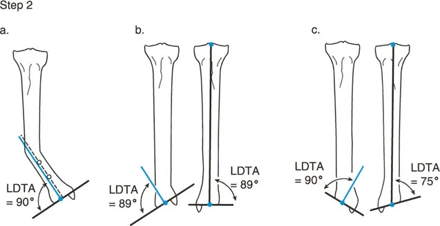
| mLDTA | Mechanical Lateral Distal Tibial Angle | 89 degrees | 86 to 92 degrees |
| JLCA | Joint Line Convergence Angle | 0 to 2 degrees | 0 to 2 degrees |
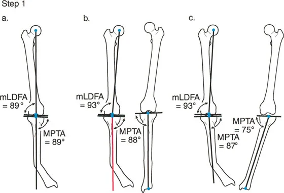
Clinical Application of Joint Angles
Mechanical Lateral Distal Femoral Angle evaluates the distal femur. An mLDFA greater than 90 degrees indicates distal femoral varus. An mLDFA less than 85 degrees indicates distal femoral valgus.
Medial Proximal Tibial Angle evaluates the proximal tibia. An MPTA less than 85 degrees indicates proximal tibial varus. An MPTA greater than 90 degrees indicates proximal tibial valgus.
Joint Line Convergence Angle evaluates the soft tissues and ligamentous stability of the knee. It is the angle formed between the distal femoral articular line and the proximal tibial articular line. A JLCA greater than 2 degrees indicates intra articular deformity, ligamentous laxity, or asymmetric cartilage loss.
If the Mechanical Axis Deviation is abnormal, but both the mLDFA and MPTA are within normal limits, the surgeon must look at the JLCA. A widened JLCA means the deformity is not bony, but rather soft tissue driven, and a bony osteotomy may be contraindicated or require overcorrection.
Defining the Center of Rotation of Angulation
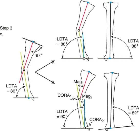
When a bone is deformed, drawing the proximal axis line and the distal axis line will result in two lines that are no longer collinear. Because they are angled relative to one another, if you extend them, they will eventually intersect.
The exact point at which these proximal and distal axis lines intersect is called the Center of Rotation of Angulation.
The Center of Rotation of Angulation is the holy grail of deformity planning. It dictates precisely where the apex of the deformity lies and consequently where the optimal level of the osteotomy or hinge placement for a dynamic external fixator should be located.
To fully define the Center of Rotation of Angulation, the surgeon must also determine the Transverse Bisector Line. This is the line that perfectly bisects the obtuse and acute angles formed by the intersecting proximal and distal axes. The Transverse Bisector Line is critical because it represents the plane along which pure angulatory correction can occur without inducing unwanted translation.
The magnitude of the deformity is simply the angle measured between the proximal and distal axes. This is the exact number of degrees by which the bone must be corrected to restore collinearity.
Paley Osteotomy Rules for Deformity Correction
Identifying the Center of Rotation of Angulation is only the first half of the battle. The surgeon must then decide where to cut the bone the osteotomy and where to rotate the bone the hinge. Dr Paley codified three fundamental rules that dictate the relationship between the Center of Rotation of Angulation, the osteotomy site, and the hinge axis.
Understanding these three rules allows the surgeon to manipulate bone segments predictably, avoiding iatrogenic translation or creating intentional translation when clinically necessary.
Osteotomy Rule 1 Pure Angulation
Paley Rule 1 states that if the osteotomy and the hinge axis are both placed exactly at the Center of Rotation of Angulation, the correction will result in pure angulation.
In this scenario, the proximal and distal axes will realign to become perfectly collinear without any displacement of the bone ends. The cortex at the concavity of the deformity acts as the hinge. When the bone is opened opening wedge or closed closing wedge at the Center of Rotation of Angulation, the mechanical axis is restored flawlessly. This is the most biomechanically sound and technically straightforward correction, ideal for diaphyseal deformities where the Center of Rotation of Angulation is easily accessible.
Osteotomy Rule 2 Angulation with Intentional Translation
Paley Rule 2 states that if the hinge axis is placed at the Center of Rotation of Angulation, but the osteotomy is performed at a different level outside the Center of Rotation of Angulation, the correction will result in angulation combined with translation.
Despite the translation of the bone ends at the osteotomy site, the proximal and distal mechanical axes will still become perfectly collinear. Why would a surgeon choose this? Often, the Center of Rotation of Angulation is located directly within a joint space or in an area of poor bone stock where an osteotomy is impossible or unsafe. By placing the hinge virtually at the Center of Rotation of Angulation using an external fixator or specialized internal plating techniques and cutting the bone at a safer metaphyseal or diaphyseal level, the surgeon achieves perfect axis restoration. The resulting translation at the cut site is a necessary and acceptable byproduct of restoring the mechanical axis.
Osteotomy Rule 3 Secondary Translation Deformity
Paley Rule 3 states that if both the osteotomy and the hinge axis are placed outside the Center of Rotation of Angulation, the correction will result in a secondary translation deformity.
In this scenario, the proximal and distal axes will become parallel to each other, but they will not be collinear. This creates a new mechanical axis deviation. Rule 3 is generally considered a surgical error or a pitfall of poor preoperative planning. It occurs when a surgeon simply cuts the bone where it is convenient and hinges the bone at the cut site, completely ignoring the true Center of Rotation of Angulation. This leaves the patient with a persistent mechanical axis shift, even if the bone looks straighter on a localized radiograph. Rule 3 should be avoided unless the surgeon is intentionally trying to translate a limb to compensate for a joint deformity that cannot be corrected directly.
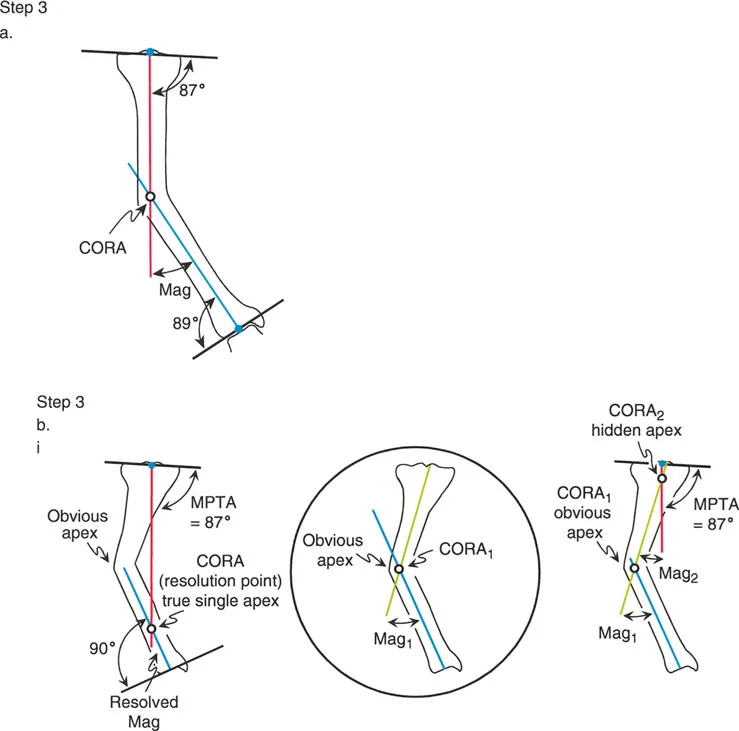
Advanced Concepts in Multi Apical Deformities
Not all bones have a single distinct bend. Many congenital conditions, metabolic bone diseases, or malunions following complex trauma result in multi apical deformities. In these cases, the bone has a sweeping bow or multiple distinct points of angulation.
When drawing the proximal and distal axes in a multi apical deformity, they will not accurately represent the entire bone. The surgeon must break the bone down into three or more segments proximal, middle, and distal.
By drawing the axis for each individual segment, the surgeon will identify multiple Centers of Rotation of Angulation. Each Center of Rotation of Angulation represents a distinct apex that may require its own osteotomy. Attempting to correct a multi apical deformity with a single osteotomy based on the extreme proximal and distal ends will inevitably lead to massive translation, shortening, and failure to restore the true mechanical axis. Mastery of Paley principles requires the patience to map every segment and address each Center of Rotation of Angulation sequentially.
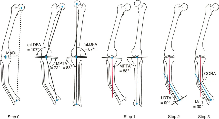
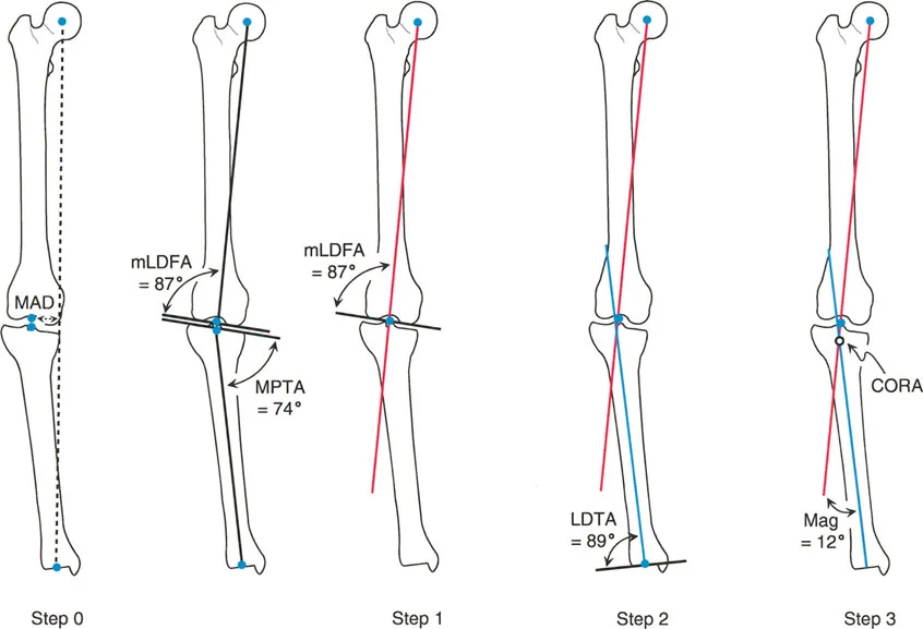
Step by Step Frontal Plane Planning Guide
Translating these theoretical biomechanical concepts into a concrete surgical plan requires a disciplined reproducible workflow. The following step by step guide outlines the standard operating procedure for frontal plane deformity planning.
- Obtain Proper Radiographs Ensure you have a high quality 51 inch standing full length radiograph. The patella must be facing strictly forward. If the foot is externally rotated, let it be. Correcting for foot position instead of patella position will create a rotational artifact that invalidates frontal plane planning.
- Perform the Malalignment Test Draw the mechanical axis of the entire lower limb from the center of the femoral head to the center of the ankle plafond.
- Quantify the Mechanical Axis Deviation Measure the distance from the center of the knee joint to the mechanical axis line. Determine if the deviation is medial varus or lateral valgus.
- Draw the Joint Lines Draw the articular reference lines for the proximal femur, distal femur, proximal tibia, and distal tibia.
- Perform the Malorientation Test Measure the mLDFA, MPTA, and JLCA. Compare these measurements to standard normal values to determine which bone segment is responsible for the mechanical axis deviation.
- Draw the Proximal and Distal Axes Focus on the deformed bone. Draw the mechanical or anatomic axis of the proximal segment and the distal segment.
- Locate the Center of Rotation of Angulation Mark the exact intersection point of the proximal and distal axes. Measure the magnitude of the deformity angle.
- Draw the Transverse Bisector Line Bisect the angle formed by the intersecting axes to identify the plane of pure angulation.
- Select the Osteotomy Level Determine if the bone can be cut safely at the Center of Rotation of Angulation. If yes, apply Paley Rule 1. If the Center of Rotation of Angulation is periarticular or unsafe, select a safe osteotomy site and apply Paley Rule 2, ensuring the hinge remains at the Center of Rotation of Angulation.
- Plan the Fixation Decide whether internal fixation plates or nails or external fixation circular frames will be used to execute and stabilize the planned correction.
Clinical Pearls for the Deformity Surgeon
To elevate your practice from basic competence to true mastery, internalize these high yield clinical pearls derived from decades of deformity correction experience.
- Patella Forward is Paramount Never plan a frontal plane deformity on a radiograph where the patella is not pointing straight ahead. A radiograph taken with the foot forward in a patient with tibial torsion will project a false varus or valgus deformity due to the parallax effect.
- Beware the Joint Line Convergence Angle A common trap for junior surgeons is performing a massive tibial osteotomy for a varus knee, only to realize postoperatively that the varus was driven by lateral ligamentous laxity or medial cartilage loss. Always measure the JLCA. If it is greater than 2 degrees, you must account for soft tissue balancing, or you will overcorrect the bone.
- Anatomic vs Mechanical Axis Preference When planning diaphyseal deformities, using the anatomic axes is often easier and more practical, especially if intramedullary nailing is planned. When planning periarticular deformities, mechanical axes are superior because they directly reference the joint orientation.
- The Sagittal Plane Exists While this masterclass focuses on the frontal plane, bones exist in three dimensions. A purely frontal plane plan is incomplete. You must perform the exact same rigorous axis planning on the lateral radiograph to evaluate for procurvatum or recurvatum.
- Rule 2 is Your Best Friend In complex trauma malunions, the Center of Rotation of Angulation is almost always near the joint. Attempting a Rule 1 osteotomy here risks intra articular fracture or avascular necrosis. Mastering Rule 2 allows you to cut in healthy diaphyseal bone while achieving perfect mechanical alignment.
Conclusion
The correction of complex limb deformities is a demanding discipline that leaves no room for guesswork. The transition from eyeballing alignment to executing mathematically precise corrections is what defines the modern orthopedic surgeon. By strictly adhering to the principles established by Dr Dror Paley, surgeons can deconstruct even the most intimidating deformities into manageable logical steps.
Mastery of the Center of Rotation of Angulation, profound understanding of the Mechanical Axis Deviation, and disciplined application of the Osteotomy Rules ensure that every surgical intervention is biomechanically sound. Ultimately, this mathematical rigor translates directly into restored joint kinematics, prevention of degenerative joint disease, and the return of pain free function for the patient.
!!! info "Academic Resource & Medical Review"
This academic resource was prepared and medically reviewed by Prof. Dr. Mohammed Hutaif, Consultant Orthopedic & Spine Surgeon. It is formulated specifically for medical students, orthopedic residents, and surgeons preparing for high-stakes board examinations (AAOS, FRCS Tr & Orth, Arab Board).
!!! warning "Disclaimer"
The surgical techniques, classifications, and clinical guidelines presented herein are for educational and academic review purposes only. They are not intended to replace institutional protocols or independent clinical judgment.
You Might Also Like