Mastering Limb Deformity Correction: Paley's Principles, Hardware & Osteotomy
Key Takeaway
Paley's principles provide a geometric framework for precise limb deformity correction, quantifying mechanical axis deviation (MAD) and joint angles. They guide osteotomy planning, CORA identification, and external fixator application, transforming intuitive surgery into an exact science for orthopedic surgeons.
Introduction to Advanced Deformity Correction Biomechanics
The foundation of modern orthopedic deformity correction rests upon the biomechanical and biological principles pioneered by Gavriil Ilizarov and meticulously refined, mathematically quantified, and systematized by Dr. Dror Paley. For the orthopedic surgeon-in-training, mastering these concepts is not merely an academic exercise; it is the absolute prerequisite for executing complex three-dimensional limb reconstructions.
Before a surgeon can safely apply a circular frame or perform an osteotomy, they must intimately understand the Mechanical Axis Deviation (MAD) and the normal joint orientation angles. Paley's principles provide a universal geometric language to identify where a bone is deformed, by how much, and exactly how to fix it. This comprehensive masterclass delves deep into the critical considerations of hardware application and osteotomy execution, exploring the intricate dance between the Center of Rotation of Angulation (CORA), the Angulation Correction Axis (ACA), and the application of circular external fixation devices.
The Legacy of Ilizarov and Paley
Gavriil Ilizarov revolutionized orthopedics by discovering the "tension-stress effect," which dictates that living tissue subjected to slow, steady distraction becomes metabolically activated, resulting in the genesis of new bone (distraction osteogenesis) and soft tissue. However, it was Dr. Dror Paley who introduced the rigorous mathematical and geometric framework required to apply Ilizarov's biological principles with pinpoint accuracy. Paley transitioned deformity correction from an intuitive art form into a reproducible, exact science.
Understanding Mechanical Axis Deviation
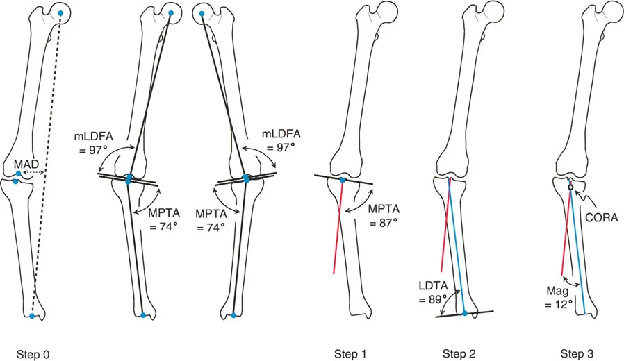
The mechanical axis of the lower extremity is defined by a line drawn from the center of the femoral head to the center of the ankle joint (the tibial plafond). In a normally aligned limb, this line should pass just medial to the center of the knee joint (approximately 8mm medial to the midpoint of the tibial plateau).
Mechanical Axis Deviation occurs when this line shifts outside the normal parameters. A medial shift indicates a varus deformity, placing excessive load on the medial compartment of the knee, while a lateral shift indicates a valgus deformity, overloading the lateral compartment. Quantifying the MAD is the very first step in preoperative planning, as the ultimate goal of any deformity correction surgery is to restore the mechanical axis to its neutral, physiologic position.
Defining the Geometric Language of Deformity
To correct a deformity, you must first speak the language of joint orientation. The orientation of the major joints (hip, knee, and ankle) relative to the mechanical and anatomical axes of the femur and tibia dictates the parameters for surgical reconstruction.
Normal Joint Orientation Angles
Joint orientation angles are measured on standing, long-leg anteroposterior (AP) and lateral radiographs. They are defined by the intersection of the joint line with either the mechanical or anatomical axis of the bone.
Below is a high-yield reference table for the standard joint orientation angles in the coronal plane. Mastering these values is essential for identifying the exact location and magnitude of a deformity.
| Angle Acronym | Full Anatomical Name | Normal Value Range | Average |
|---|---|---|---|
| mLDFA | Mechanical Lateral Distal Femoral Angle | 85° - 90° | 87° |
| aLDFA | Anatomical Lateral Distal Femoral Angle | 79° - 83° | 81° |
| MPTA | Medial Proximal Tibial Angle | 85° - 90° | 87° |
| LPFA | Lateral Proximal Femoral Angle | 85° - 95° | 90° |
| LDTA | Lateral Distal Tibial Angle | 86° - 92° | 89° |
| JLCA | Joint Line Congruency Angle | 0° - 2° | 0° |
Surgical Pearl for Joint Angles
* Always evaluate the Joint Line Congruency Angle (JLCA). A JLCA greater than 2 degrees indicates either ligamentous laxity (e.g., medial collateral ligament stretching in severe varus) or intra-articular cartilage loss. If you fail to account for an abnormal JLCA, your extra-articular osteotomy will result in an under-corrected or over-corrected limb.
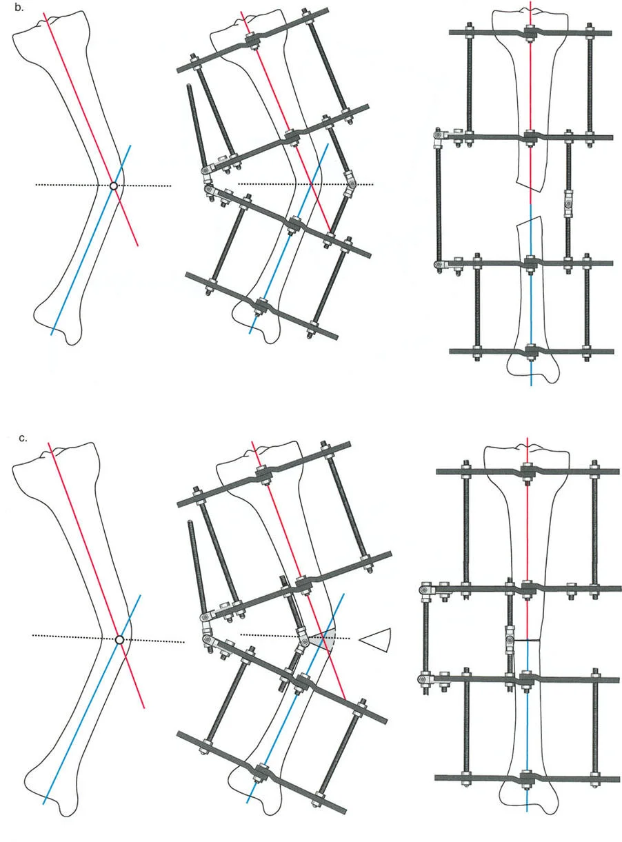
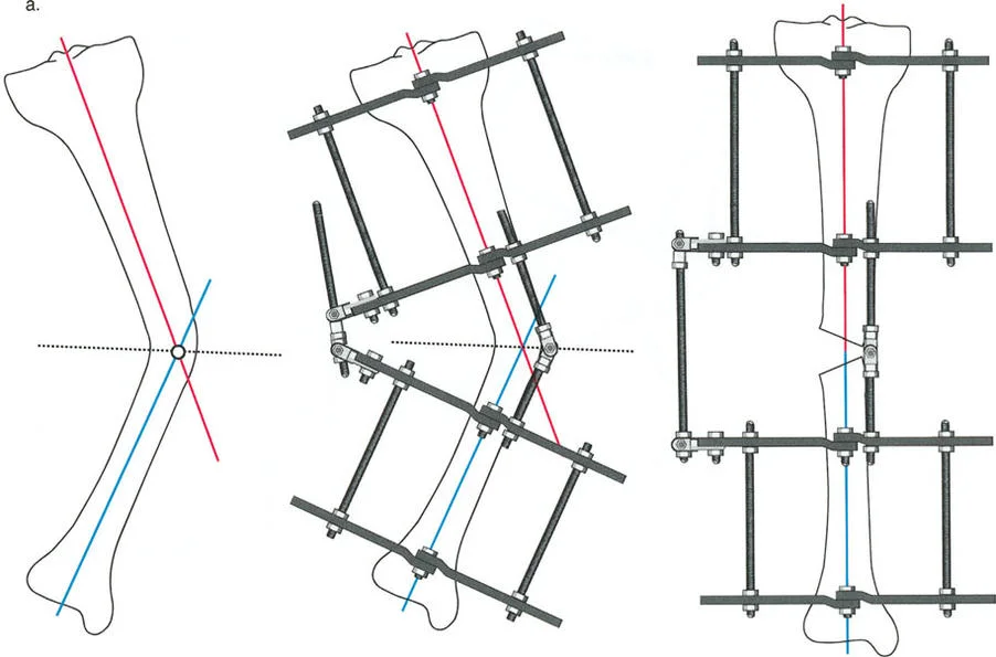
Center of Rotation of Angulation and the Bisector Line
The Center of Rotation of Angulation (CORA) is the cornerstone of Paley's method. It represents the intersection point of the proximal and distal mechanical (or anatomical) axes of a deformed bone.
When a bone is deformed, the proximal segment has its own axis, and the distal segment has its own axis. Where these two lines cross is the CORA. The angle formed by this intersection represents the true magnitude of the angular deformity.
Once the CORA is identified, the surgeon must draw the Bisector Line. The bisector line is a transverse line that perfectly bisects the obtuse and acute angles formed by the intersecting proximal and distal axes at the CORA. The relationship between the osteotomy site, the CORA, and the bisector line forms the basis of Paley's Osteotomy Rules, which dictate whether a bone will open, close, or translate during correction.
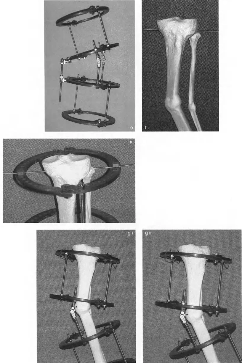
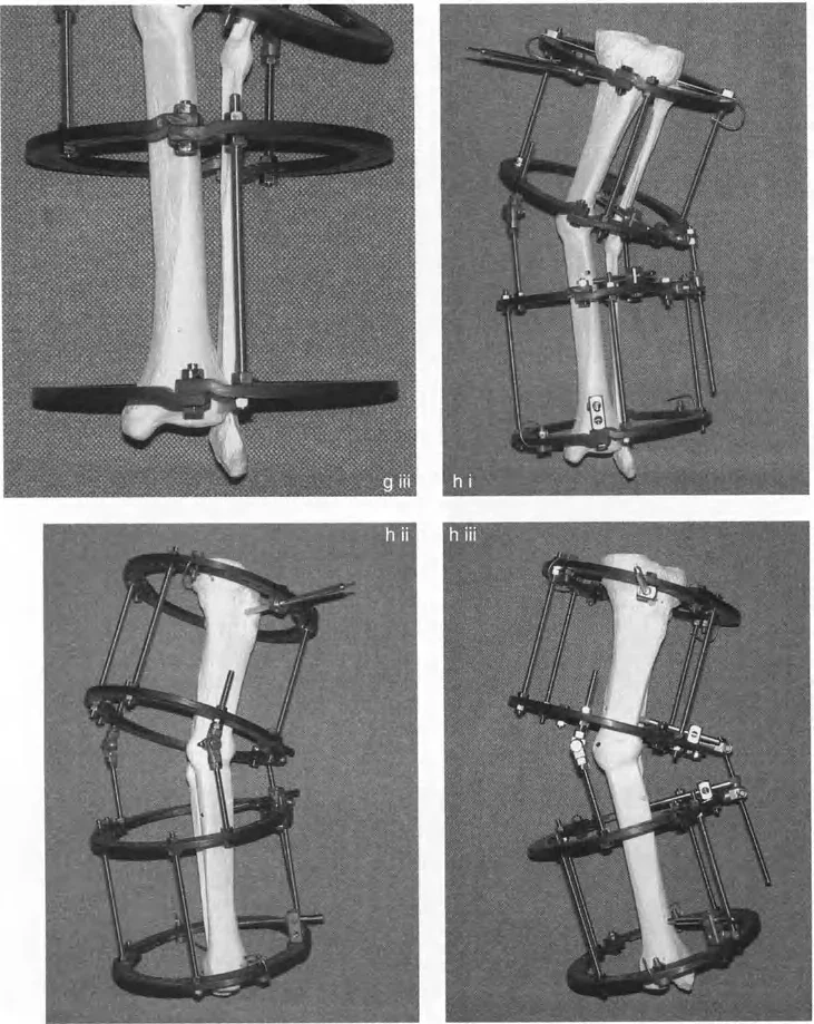
Preconstructing the Circular External Fixator
The success of a deformity correction surgery is largely determined before the first incision is ever made. Preconstruction of the circular apparatus (such as the traditional Ilizarov frame or the hexapod-based Taylor Spatial Frame) is a vital step that bridges radiographic planning with intraoperative execution.
The Rationale for Back Table Assembly
Building the frame on the back table prior to bringing the patient into the operating room provides several distinct advantages
1. Surgical Efficiency It drastically reduces operative time and tourniquet time (if used).
2. Radiation Reduction It minimizes the amount of intraoperative fluoroscopy required to piece together rings and struts.
3. Precision Engineering It ensures that the mechanical construct precisely matches the preoperative geometric blueprint, allowing the surgeon to verify hinge placement and strut lengths in a sterile, controlled environment.
Frontal and Oblique Plane Deformity Planning
Preconstruction follows strict geometric rules derived from the graphical planning of the deformity. The apparatus must be built with hinges placed in graphically predetermined holes on the rings.
When dealing with a simple frontal plane deformity (pure varus or valgus), the hinges are placed on the medial and lateral aspects of the ring, parallel to the sagittal plane. However, pure single-plane deformities are exceedingly rare in clinical practice. Most clinical deformities exist in an oblique plane—a complex three-dimensional combination of frontal and sagittal plane deformities (e.g., varus combined with recurvatum).
To address an oblique plane deformity, the apparatus is centered on the leg. First, the leg is positioned in the frontal plane with the patella facing strictly forward—mirroring the exact position in which the initial long-leg standing radiographs were obtained. The hinges must be oriented so that their axis is perpendicular to the plane of the maximum deformity.
Key Takeaways for Oblique Deformities
* Never treat a multi-planar deformity as two separate problems. Calculate the true oblique plane of deformity using graphical analysis or specialized software.
* The Angulation Correction Axis (ACA) must be placed exactly 90 degrees (orthogonal) to the true oblique plane of the deformity to ensure simultaneous correction of both the coronal and sagittal components without inducing unwanted translation.
Executing Frame Application and Alignment
Once the frame is preconstructed, transferring it to the patient's limb requires meticulous attention to detail. The frame is not merely a stabilizing device; it is a dynamic tool that will dictate the trajectory of bone healing.
Establishing the Proximal Reference
The proximal reference wire is the absolute anchor of your entire construct. If this wire is malpositioned, the entire frame will be malaligned, compromising the correction and potentially leading to catastrophic joint malorientation.
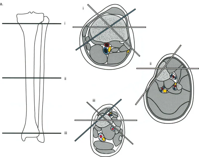
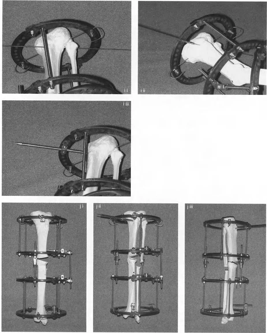
- Wire Insertion Insert the proximal reference wire strictly perpendicular to the mechanical axis of the proximal bone segment. In the tibia, this is typically parallel to the knee joint line in the coronal plane.
- Frame Attachment The preconstructed frame is attached to this reference wire and tensioned appropriately (usually 130 kg for adult tibial wires).
- Sagittal Alignment The frame is then rotated until the central bolts of the hinges overlap perfectly when viewed under the image intensifier (fluoroscopy) in the lateral plane.
By overlapping these bolts, you ensure that the sagittal plane of the apparatus perfectly aligns with the sagittal plane of the leg. Because the orientation of the ACA (the imaginary line connecting the two hinges) is planned relative to the sagittal plane, overlapping the hinges automatically aligns the apparatus to the oblique plane angular deformity.
Adjusting Hinge Level and Distal Fixation
Even with meticulous preoperative radiographic planning, magnification errors on standard X-rays are inevitable. Therefore, once the apparatus is fixed proximally, the surgeon must physically verify the level of the hinges relative to the level of the CORA on the bone.
The level of the CORA is mapped onto the bone by measuring its distance from reliable anatomical landmarks, such as the knee joint line or the ankle plafond.
If the proximal reference wire is perfectly perpendicular to the long axis of the proximal tibia, and the apparatus is correctly rotated, the only remaining adjustment is the longitudinal level of the hinges.
* Adjust the threaded rods to match the hinge length to the exact level of the CORA.
* Ensure the distal ring sits approximately 1 to 2 cm proximal to the ankle plafond. This space is critical to allow for soft tissue clearance, postoperative swelling, and unimpeded joint motion during the lengthening phase.
* Once aligned, the distal reference wire is inserted. This wire usually captures both the tibia and fibula to prevent proximal migration of the fibula during distraction.
The Osteotomy Rules of Paley
The most critical concept in Paley's teachings is the mathematical and spatial relationship between the osteotomy, the CORA, and the ACA (the hinges). The spatial placement of your hinges dictates exactly how the bone ends will move relative to one another in three-dimensional space.
To achieve pure angular correction without translation, the ACA must pass directly through the CORA. However, the position of the ACA along the bisector line determines whether the bone will undergo an opening wedge, closing wedge, or a combination of correction and lengthening.
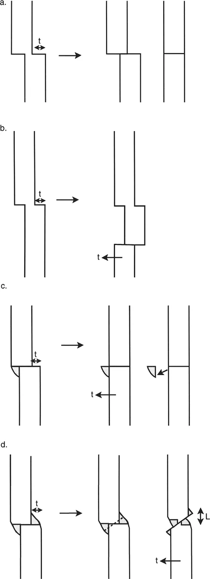
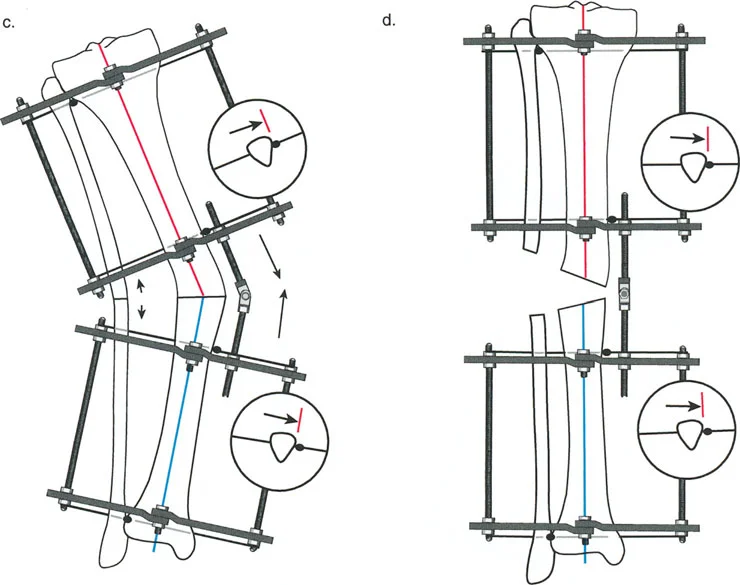
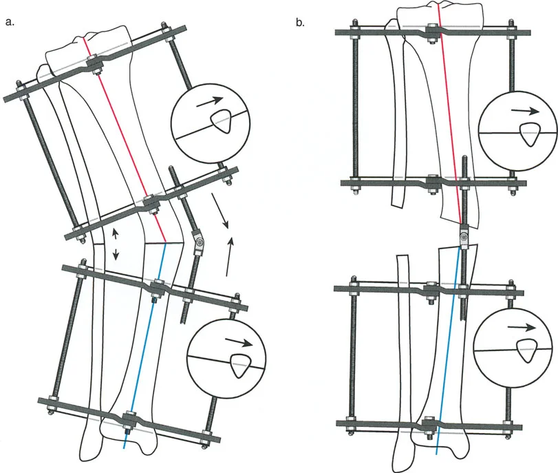
Rule One The Opening Wedge Correction
Paley's First Osteotomy Rule states that when the osteotomy and the ACA both pass through the CORA, the bone ends will angulate without any translation.
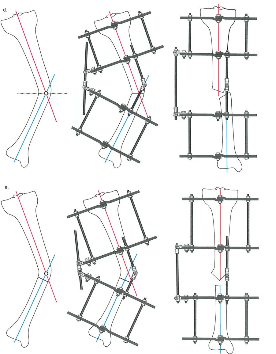
If the hinge (ACA) is placed exactly on the bisector line and positioned directly on the convex cortex of the deformity, the result is an Opening Wedge Correction.
* Mechanism As the hinges are distracted, the concave cortex opens, creating a wedge-shaped gap.
* Clinical Application This is the most common technique used in distraction osteogenesis. It allows for simultaneous correction of angulation and lengthening. Because the bone ends do not translate, the mechanical axis is perfectly restored.
* Biological Requirement Because a gap is created, this technique relies entirely on the body's ability to generate new bone (regenerate) within the distraction gap.
Rule Two The Closing Wedge Correction
Paley's Second Osteotomy Rule addresses situations where the osteotomy is performed at a different level than the CORA, but the ACA remains aligned with the CORA.
If the ACA is placed on the bisector line but positioned on the concave cortex of the deformity, and the osteotomy is performed at the CORA, the result is a Closing Wedge Correction.
* Mechanism As the deformity is corrected, the convex cortex compresses. In traditional internal fixation, a physical wedge of bone is removed. In external fixation with a dome osteotomy, the bone ends slide along one another.
* Clinical Application This is utilized when lengthening is not desired, or when the soft tissue envelope on the concave side is too tight to permit an opening wedge.
* Translation Effect Because the osteotomy is at the CORA, the bone ends will angulate without translation. However, if the osteotomy is made away from the CORA (while the ACA remains at the CORA), the bone ends will undergo a predictable, necessary translation to ensure the mechanical axes realign perfectly.
Rule Three Translation and Simultaneous Correction
Paley's Third Osteotomy Rule is the most complex and describes what happens when the ACA does not pass through the CORA.
If the osteotomy is performed at the CORA, but the ACA is placed away from the CORA (not on the bisector line), the result is Angulation with Translation.
* Mechanism The bone ends will angulate, but because the axis of rotation is eccentric to the deformity, the proximal and distal segments will translate relative to one another.
* Iatrogenic Deformity If this is done unintentionally, it results in a secondary translation deformity, shifting the mechanical axis and creating a new MAD.
* Therapeutic Application Surgeons intentionally utilize Rule Three when a bone has both an angular deformity and a pre-existing translational deformity. By carefully calculating the offset of the ACA from the CORA, the surgeon can simultaneously correct the angulation and reduce the translation with a single hinge mechanism.
Advanced Considerations in Hardware Application
Mastering the geometric rules is only half the battle. The biological execution of the osteotomy and the biomechanical stability of the hardware are equally vital for ensuring a successful distraction osteogenesis process.
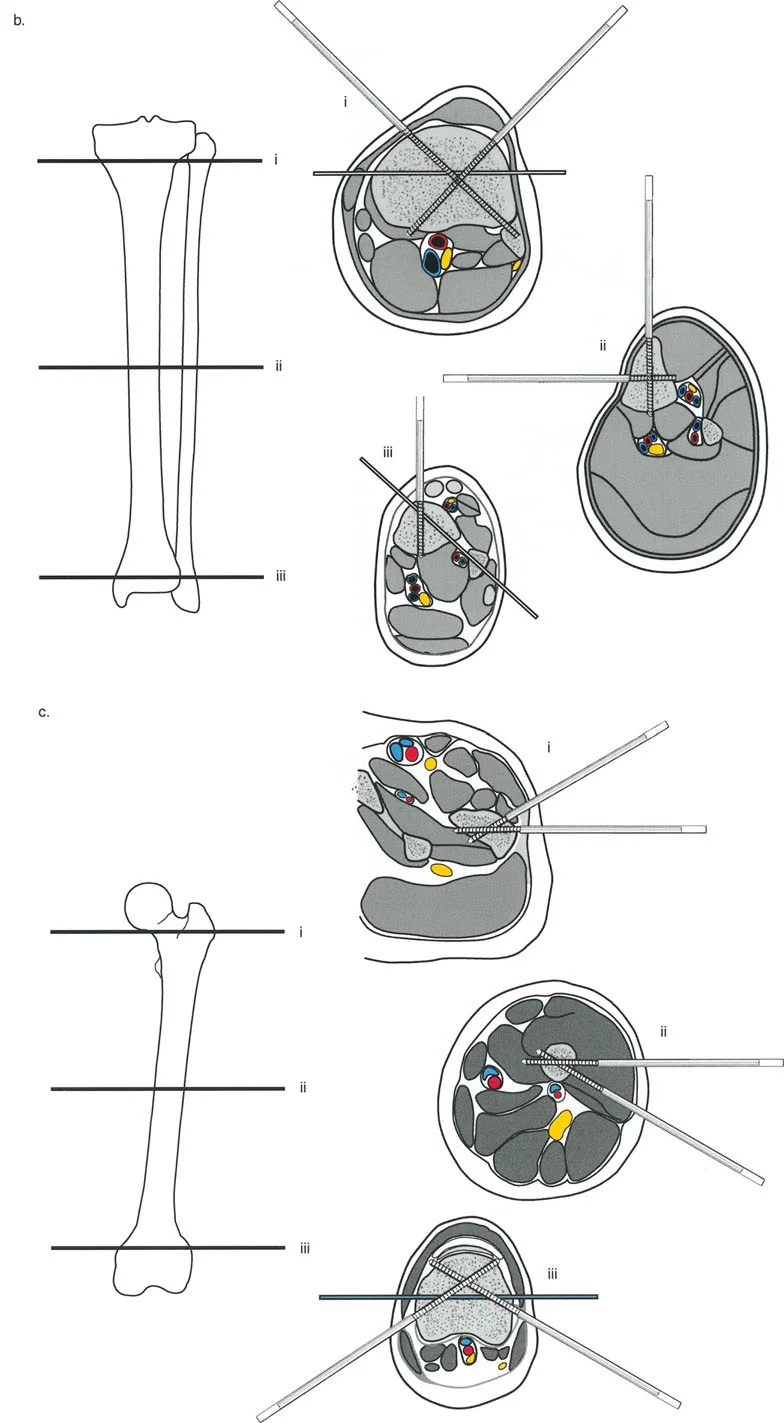
Wire and Half Pin Biomechanics
Circular external fixation relies on a combination of tensioned smooth wires, olive wires, and half-pins to achieve multi-planar stability.
- Smooth Wires Provide axial micro-motion, which stimulates osteogenesis. They must be tensioned to act like spokes on a bicycle wheel.
- Olive Wires Feature a small bead (olive) that acts as a physical stop against the bone cortex. They are strategically placed to prevent unwanted translation of the bone segment along the wire during distraction, and can be used to forcefully pull a bone segment into alignment.
- Half-Pins Provide rigid cantilever bending stiffness. Modern constructs often use a hybrid approach, combining tensioned wires for biological stimulation and hydroxyapatite-coated half-pins for enhanced stability and prevention of pin-tract loosening.
Soft Tissue Management During Osteotomy
The method by which the bone is cut dictates the quality of the regenerate bone. A traumatic osteotomy that destroys the periosteum and endosteal blood supply will lead to delayed union, non-union, or premature consolidation.
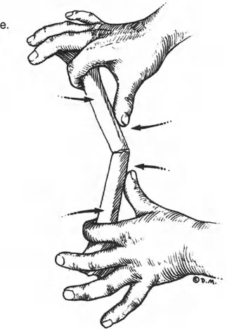
Steps for a Biologically Sound Corticotomy
1. Minimal Incision Make a small (1-2 cm) incision directly over the planned osteotomy site, carefully avoiding neurovascular structures.
2. Periosteal Preservation Elevate the periosteum meticulously. The periosteum contains the cambium layer, which is heavily populated with osteoprogenitor cells critical for regenerate formation.
3. Multiple Drill Holes Use a sharp, fluted drill bit to make multiple, contiguous holes through the near cortex, passing through the medullary canal to the far cortex. Use copious cold saline irrigation to prevent thermal necrosis of the bone.
4. Osteotome Completion Insert a sharp, narrow osteotome and connect the drill holes. Twist the osteotome gently to crack the remaining cortical bridges rather than forcefully hammering through them. This preserves the medullary blood supply as much as possible.
5. The Latency Period After the osteotomy is complete and the frame is secured, wait 5 to 7 days before initiating distraction. This latency period allows for the initial inflammatory phase of fracture healing to subside and for early soft callus to form, which will then be stretched during the distraction phase.
Conclusion to Deformity Correction Mastery
Mastering Paley's principles of deformity correction requires a paradigm shift for the orthopedic surgeon. It demands moving away from pure visual estimation and embracing rigorous geometric and mathematical planning. By intimately understanding the Mechanical Axis Deviation, joint orientation angles, and the spatial relationship between the CORA and the ACA, surgeons can predictably and safely correct the most complex three-dimensional limb deformities.
Whether utilizing traditional Ilizarov frames or advanced hexapod technology, the biological rules of tissue preservation and the geometric rules of hinge placement remain absolute. Through meticulous preoperative planning, precise back-table preconstruction, and biologically respectful osteotomy techniques, the surgeon transforms hardware and mathematics into restored function and anatomy for the patient.
!!! info "Academic Resource & Medical Review"
This academic resource was prepared and medically reviewed by Prof. Dr. Mohammed Hutaif, Consultant Orthopedic & Spine Surgeon. It is formulated specifically for medical students, orthopedic residents, and surgeons preparing for high-stakes board examinations (AAOS, FRCS Tr & Orth, Arab Board).
!!! warning "Disclaimer"
The surgical techniques, classifications, and clinical guidelines presented herein are for educational and academic review purposes only. They are not intended to replace institutional protocols or independent clinical judgment.
You Might Also Like