Mastering Precision: Paley's Principles for Orthopedic Deformity Correction & Osteotomy
Key Takeaway
Paley's principles are foundational for precise orthopedic deformity correction. They involve meticulous calculation of CORA, MAD, and joint orientation angles. These principles guide osteotomy planning and execution, ensuring accurate multi-planar limb realignment and optimal biomechanical outcomes.
Introduction to Advanced Deformity Correction and Biomechanics
The evolution of orthopedic deformity correction represents one of the most profound paradigm shifts in modern surgical science. Historically, correcting a malaligned limb was an exercise in estimation, relying heavily on rudimentary cast wedging, simple closing wedge osteotomies, and the subjective visual assessment of the operating surgeon. Today, the field has transitioned into a highly precise, mathematically driven discipline. At the absolute forefront of this surgical revolution are the foundational principles established by Dr Dror Paley.
Paley methodologies emphasize the meticulous calculation of the Center of Rotation of Angulation CORA, the quantification of Mechanical Axis Deviation MAD, and the precise application of joint orientation angles. However, mathematical planning on a digital radiograph is only the first half of the battle. The successful intraoperative execution of a complex deformity correction relies heavily on the surgeon absolute mastery of hardware biomechanics, soft tissue envelope management, and osteotomy considerations.
When correcting complex multi apical deformities of the lower extremities such as severe genu varum, genu valgum, or multi planar post traumatic malunions the surgeon must navigate the treacherous waters of three dimensional biomechanics. A correction that appears radiographically flawless in the frontal coronal plane can easily mask a catastrophic biomechanical failure in the sagittal plane if the chosen hardware lacks the necessary rigidity and orthogonal control.
This comprehensive guide is designed specifically for orthopedic surgeons, residents, and fellows. It delves deep into the intricate relationship between osteotomy design and hardware selection. We will explore the biomechanical pitfalls of monolateral external fixation, the revolutionary hybrid technique of Fixator Assisted Nailing FAN, and the indispensable biomechanical role of blocking screws in maintaining flawless multi planar alignment.
Paley Principles The Mathematical Foundation of Surgical Planning
Before a scalpel touches the skin, before a drill breaches the near cortex, and before an osteotome is struck, the orthopedic surgeon must have a flawless, mathematically verified blueprint. Paley principles dictate that every bone deformity has a specific magnitude, a specific plane of maximum deformity, and a unique apex. Understanding and applying these geometric truths separates an acceptable outcome from an exceptional one.
Understanding Mechanical Axis Deviation MAD
The Mechanical Axis Deviation MAD is the clinical and radiographic starting point for all lower extremity deformity analysis. In a normal well aligned lower extremity, the mechanical axis defined as a straight line drawn from the center of the femoral head to the center of the tibial plafond should pass precisely through the center of the knee joint, specifically just medial to the tibial spines.
When this mechanical axis deviates medially to the center of the knee, the patient experiences a varus deformity genu varum, leading to medial compartment overload, meniscal extrusion, and early osteoarthritis. Conversely, when the axis deviates laterally, a valgus deformity genu valgum is present, overloading the lateral compartment and stretching the medial collateral ligament. The MAD is quantified in millimeters, measuring the exact perpendicular distance from the center of the knee to the mechanical axis line.
Clinical Pearls for Mechanical Axis Deviation
* Always assess MAD on a weight bearing full length standing radiograph. Supine films negate the effect of ligamentous laxity and will underestimate the true dynamic deformity.
* A normal MAD is typically 1 to 8 millimeters medial to the exact center of the knee joint.
* Bilateral MAD assessment is crucial to establish the patient baseline normal, assuming the contralateral limb is unaffected.
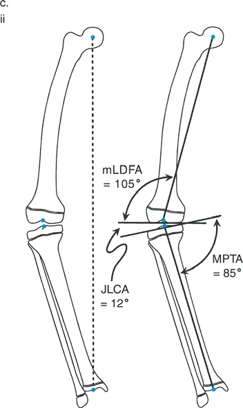
Joint Orientation Angles The mLDFA MPTA and JLCA
To understand exactly where the deformity originates whether in the femur, the tibia, or a combination of both the surgeon must measure the joint orientation angles. These angles relate the mechanical or anatomical axis of a bone segment to its respective joint line.
The primary angles utilized in frontal plane lower extremity deformity analysis include the mechanical Lateral Distal Femoral Angle mLDFA, the Medial Proximal Tibial Angle MPTA, and the Joint Line Convergence Angle JLCA. If the MAD is abnormal, these specific joint orientation angles will reveal which bone segment is the culprit, guiding the surgeon to the correct location for the osteotomy.
Normal Joint Orientation Angle Reference Table
| Angle Designation | Anatomical Landmark | Normal Range | Average Value |
|---|---|---|---|
| mLDFA | Mechanical Lateral Distal Femoral Angle | 85 to 90 degrees | 87 degrees |
| MPTA | Medial Proximal Tibial Angle | 85 to 90 degrees | 87 degrees |
| LDTA | Lateral Distal Tibial Angle | 86 to 92 degrees | 89 degrees |
| mLPFA | Mechanical Lateral Proximal Femoral Angle | 85 to 95 degrees | 90 degrees |
| JLCA | Joint Line Convergence Angle | 0 to 2 degrees | 0 degrees |
The JLCA is particularly critical. If the JLCA is greater than 2 degrees, it indicates an intra articular source of deformity, such as asymmetric cartilage loss, ligamentous laxity, or a varus thrust. Failing to account for an abnormal JLCA will result in an undercorrection or overcorrection of the osseous deformity.
Locating the Center of Rotation of Angulation CORA
Once the deformed bone is identified via abnormal joint orientation angles, the surgeon must locate the CORA. The CORA is the intersection point of the proximal and distal anatomical or mechanical axes of the deformed bone. It represents the true apex of the deformity.
To find the CORA accurately during preoperative planning
1. Draw the mid diaphyseal line anatomical axis or mechanical axis line of the proximal bone segment.
2. Draw the mid diaphyseal line or mechanical axis line of the distal bone segment.
3. The exact geometric point where these two lines intersect is the CORA.
4. The angle formed between these intersecting lines dictates the exact magnitude of the deformity that must be corrected.
Deformities can be uniapical possessing a single CORA or multi apical possessing multiple CORAs. In multi apical deformities, such as those seen in osteogenesis imperfecta or severe Paget disease, the surgeon must plan multiple osteotomies or utilize a gradual correction frame to address each apex sequentially or simultaneously.
The Three Rules of Osteotomy in Deformity Correction
Paley rules of osteotomy are the most critical biomechanical guidelines in deformity correction surgery. They dictate exactly how the bone segments will behave based on where the osteotomy cut is made relative to the CORA and the axis of correction. Mastery of these rules is non negotiable for the deformity surgeon.
Rule One The Ideal Scenario
If the osteotomy passes exactly through the CORA, and the correction is hinged precisely at the CORA, the deformity can be corrected by pure angulation. The mechanical axis will be perfectly realigned without any unintended translation shifting or step off of the bone ends.
This is the most biomechanically sound and aesthetically pleasing correction. It results in optimal cortical bone contact, facilitating rapid primary or secondary bone healing. Whenever anatomically and safely possible, the surgeon should strive to execute a Rule One osteotomy.
Rule Two The Translation Compromise
In many clinical scenarios, performing the osteotomy directly at the CORA is impossible or ill advised. The CORA might be located within a joint space, within an area of terrible soft tissue coverage, or in a zone of sclerotic avascular bone that will not heal.
If the osteotomy is performed at a different level than the CORA, but the bone segments are still angulated around the true CORA hinge, the mechanical axis will be successfully realigned. However, the bone ends will translate at the osteotomy site, creating a cortical step off. This is Rule Two. While the mechanical axis is restored perfectly, the surgeon must be prepared to manage the resulting translation, ensuring enough bony apposition remains for union. Fixation constructs must be robust enough to handle the eccentric loading caused by the translated bone segments.
Rule Three The Malalignment Trap
Rule Three represents a surgical failure of planning or execution. If the osteotomy is performed at a different level than the CORA, and the bone segments are incorrectly hinged at the osteotomy site rather than the true CORA, the mechanical axis will not align.
By hinging at the wrong location, the surgeon introduces a secondary translation deformity. The overall mechanical axis of the limb becomes zig zagged. While the joint orientation angles might look temporarily improved on a short film, a full length standing radiograph will reveal that the MAD has not been fully corrected, or worse, has been shifted into the opposite compartment. Rule Three is the primary reason why "eyeballing" a deformity correction leads to long term joint failure.
Advanced Osteotomy Design and Execution
Once the CORA is identified and the appropriate rule is selected, the surgeon must choose the geometric shape of the osteotomy. The physical cut through the bone dictates the degrees of freedom available for correction and significantly impacts the inherent stability of the osteotomy site.
The Focal Dome Osteotomy
The focal dome osteotomy is a highly advanced, semi circular C shaped bone cut. Unlike straight wedge osteotomies, the dome osteotomy allows for multi planar correction without altering the absolute length of the bone.
Because the cut is cylindrical, the bone segments can rotate along the arc of the osteotomy like a ball and socket joint. This permits simultaneous correction of angulation and translation without creating massive cortical gaps. The focal dome is particularly useful in the proximal tibia and distal femur, where preserving limb length and maximizing cancellous bone contact are paramount for rapid healing. Executing a dome osteotomy requires specialized crescentic saw blades and meticulous drill hole pre conditioning to prevent inadvertent fracture propagation into the joint.
Opening Wedge Versus Closing Wedge Osteotomies
Straight linear cuts are the traditional workhorses of orthopedic deformity correction, categorized primarily into opening wedge and closing wedge techniques.
Closing Wedge Osteotomies involve removing a triangular wedge of bone. They are inherently stable because the bone ends are compressed directly against each other. However, they inherently shorten the limb and can slacken surrounding myofascial structures.
Opening Wedge Osteotomies involve making a single cut and jacking the bone open to the desired angle, filling the resulting void with structural allograft, autograft, or relying on distraction osteogenesis. Opening wedges lengthen the limb and tighten the soft tissue envelope, which can be advantageous in addressing ligamentous laxity. However, they are inherently less stable than closing wedges and require highly rigid internal fixation, such as locking plates, to prevent collapse of the wedge.
Hardware Selection and Multi Planar Control
The most brilliant mathematical preoperative plan is entirely useless if the chosen hardware cannot hold the bone segments in the corrected position against the massive deforming forces of the lower extremity musculature and weight bearing loads.
Biomechanical Pitfalls of Monolateral External Fixation
Monolateral external fixators, while excellent for rapid trauma stabilization, present significant biomechanical challenges in complex deformity correction. Because the fixator sits entirely on one side of the limb, it is subjected to massive cantilever bending forces.
While a monolateral frame might hold a frontal plane coronal correction adequately, it often fails to control the sagittal plane. As the patient weight bears, the bone segments can flex or extend at the osteotomy site, leading to a secondary procurvatum or recurvatum deformity. Furthermore, monolateral frames offer very poor control over axial rotation. For true multi planar control, surgeons often must escalate to circular hexapod frames like the Taylor Spatial Frame, which utilize tensioned wires and half pins to provide true six axis control.
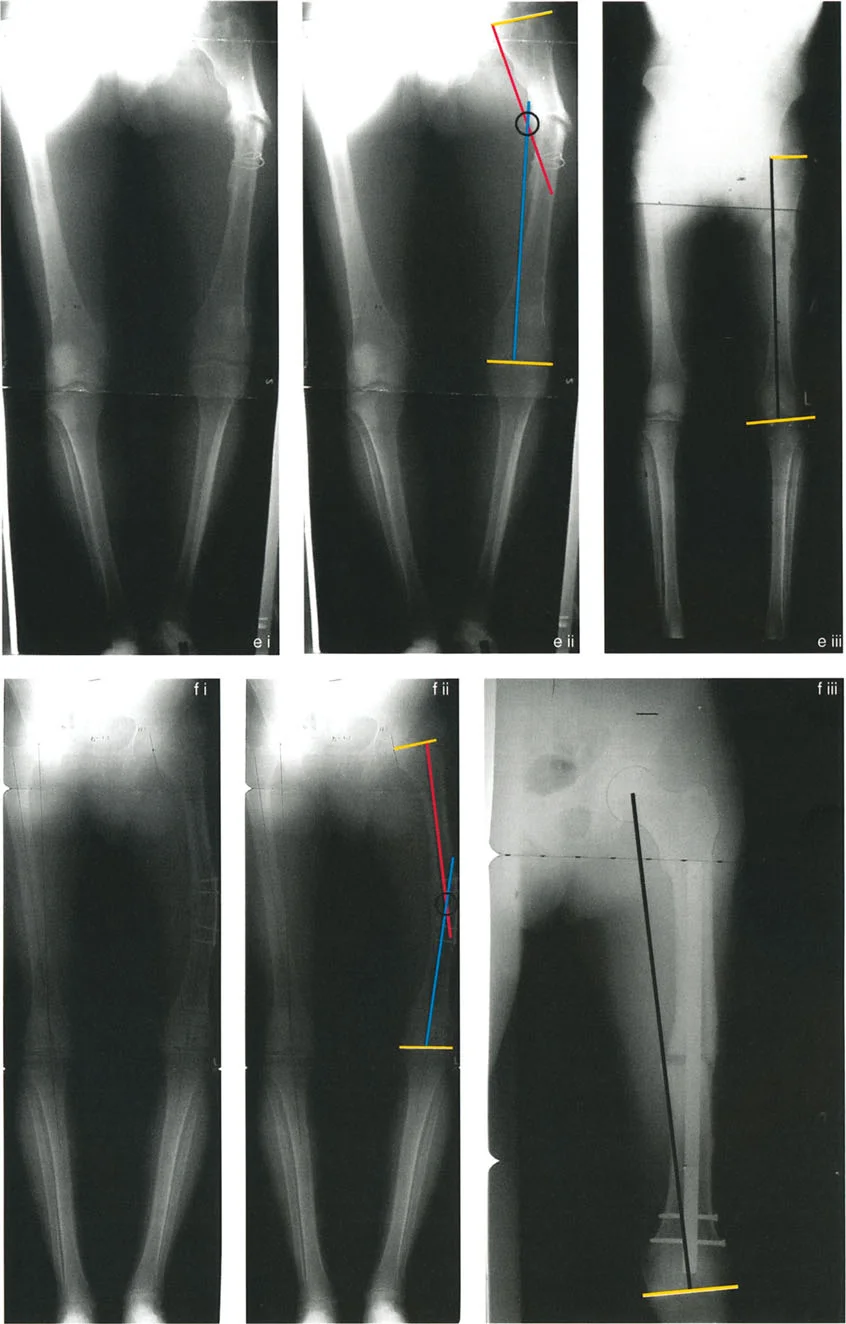
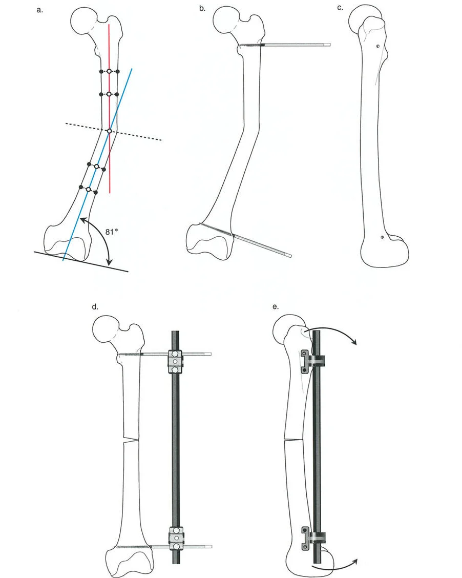
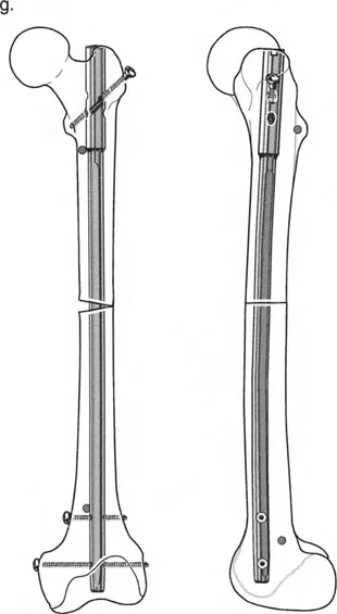
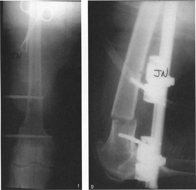
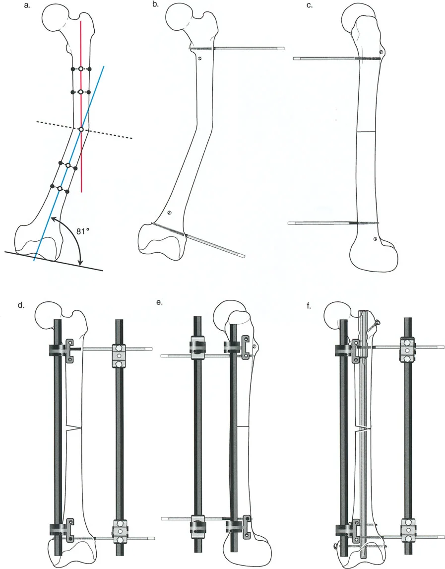
The Revolutionary Technique of Fixator Assisted Nailing FAN
To bridge the gap between the precise control of an external fixator and the patient comfort and internal stability of an intramedullary nail, Paley and colleagues popularized the Fixator Assisted Nailing FAN technique.
In the FAN technique, a sterile external fixator or specialized distraction device is applied to the limb intraoperatively. The osteotomy is performed, and the external fixator is used to dial in the exact correction in all three planes coronal, sagittal, and axial. Once perfect alignment is confirmed fluoroscopically, the intramedullary canal is reamed, and a rigid intramedullary nail is passed across the osteotomy site. The external fixator is then removed.
This technique prevents the intramedullary nail from dictating the alignment. Normally, an intramedullary nail will follow the path of least resistance, often forcing the bone back into its deformed position. By using the external fixator to rigidly hold the reduction during reaming and nail insertion, the surgeon ensures the nail locks the bone into the perfectly corrected anatomical axis.
The Biomechanical Role of Blocking Screws Poller Screws
The Fixator Assisted Nailing technique relies heavily on the use of blocking screws, universally known in orthopedics as Poller screws. When correcting metaphyseal deformities, the intramedullary canal is extremely wide. A standard intramedullary nail will toggle within this wide space, leading to a loss of the corrected alignment the moment the external fixator is removed.
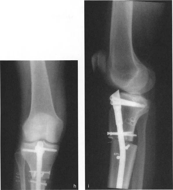
Poller screws are standard cortical screws placed strategically outside the path of the nail but within the medullary canal. They act as artificial cortices, effectively narrowing the wide metaphyseal canal and forcing the intramedullary nail into the exact center of the bone segment.
Clinical Pearls for Poller Screw Placement
* The Concavity Rule Always place the blocking screw on the concave side of the deformity.
* If correcting a varus deformity, the blocking screw goes on the medial concave side of the proximal segment and the lateral concave side of the distal segment.
* Poller screws increase the mechanical stiffness of the bone nail construct, acting as a fulcrum that resists the bending moments attempting to recreate the deformity.
* Screws must be placed before reaming to ensure the reamer is physically deflected into the correct trajectory.
Step by Step Guide to Preoperative Deformity Planning
To synthesize Paley principles into a reproducible workflow, surgeons should adhere to the following systematic approach for every deformity case.
- Obtain High Quality Imaging Acquire a weight bearing, full length, bilateral standing radiograph with the patellae oriented perfectly forward to control for rotation.
- Draw the Mechanical Axes Map the mechanical axis of the entire lower extremity, from the center of the femoral head to the center of the ankle joint.
- Calculate the MAD Measure the distance from the mechanical axis to the center of the knee. Determine if the deviation is medial varus or lateral valgus.
- Measure Joint Orientation Angles Calculate the mLDFA, MPTA, and JLCA. Compare these to normal reference values to isolate the deformed bone segment.
- Locate the CORA Draw the mechanical or anatomical axes of the proximal and distal segments of the deformed bone. Mark their intersection point.
- Determine the Osteotomy Rule Decide if the osteotomy can be performed at the CORA Rule One or if it must be performed away from the CORA Rule Two or Three. Plan for the necessary translation if utilizing Rule Two.
- Select the Hardware Choose a fixation construct locking plate, circular frame, or intramedullary nail with Poller screws that provides rigid, multi planar stability based on the osteotomy type and patient biology.
Conclusion
Mastering orthopedic deformity correction requires a profound respect for biomechanics and an unwavering commitment to mathematical precision. The days of estimating alignment are long gone, replaced by the rigorous application of Paley principles.
By meticulously calculating the Mechanical Axis Deviation, understanding the nuances of joint orientation angles, accurately locating the Center of Rotation of Angulation, and strictly adhering to the rules of osteotomy, surgeons can predictably restore normal limb alignment. When this mathematical planning is combined with advanced surgical techniques like Fixator Assisted Nailing and the strategic placement of Poller screws, the orthopedic surgeon gains absolute multi planar control, ensuring optimal biomechanical outcomes and vastly improving the long term quality of life for the patient.
!!! info "Academic Resource & Medical Review"
This academic resource was prepared and medically reviewed by Prof. Dr. Mohammed Hutaif, Consultant Orthopedic & Spine Surgeon. It is formulated specifically for medical students, orthopedic residents, and surgeons preparing for high-stakes board examinations (AAOS, FRCS Tr & Orth, Arab Board).
!!! warning "Disclaimer"
The surgical techniques, classifications, and clinical guidelines presented herein are for educational and academic review purposes only. They are not intended to replace institutional protocols or independent clinical judgment.
You Might Also Like