Mastering Deformity Correction: Paley Principles, Osteotomy Rules & Hardware Selection
Key Takeaway
Mastering orthopedic deformity correction involves understanding Paley's principles, including MAD and CORA. Precise osteotomy rules dictate angular and translational correction. Hardware selection, from locking plates to IM nails, must align with biomechanical demands to achieve flawless lower extremity realignment and prevent iatrogenic deformities.
Introduction to Reconstructive Osteotomies and Hardware Selection
In the realm of advanced orthopedic surgery, the transition from standard fracture management to complex reconstructive deformity correction requires a profound clinical and biomechanical paradigm shift. Standard fracture fixation aims to restore native, pre-injury anatomy using implants that are pre-contoured and designed for normal bone geometry. In stark contrast, reconstructive osteotomies deliberately alter bone geometry to correct Mechanical Axis Deviations MAD and restore optimal joint orientation. The surgeon is no longer simply putting broken pieces back together; they are actively re-engineering the mechanical alignment of the human skeleton.
Understanding the geometric ramifications of deformity correction hardware is paramount for orthopedic surgeons, residents, and fellows in training. Implants utilized in these procedures—such as locking plates, intramedullary nails IMN, and sophisticated external fixators—are not merely stabilizing devices. Rather, they are active instruments of geometric transformation.
When a reconstructive osteotomy is performed, the spatial relationship between the proximal and distal bone segments is manipulated around a highly specific hinge point known as the Axis of Correction of Angulation ACA. If the hardware applied does not meticulously account for the Center of Rotation of Angulation CORA, disastrous secondary iatrogenic deformities, such as unintended translation or altered leg length, will inevitably occur.
This comprehensive guide delves deep into the biomechanics of hardware selection, the precise execution of fixator-assisted plating, the management of challenging metaphyseal and diaphyseal deformities, and the rigorous application of Dr. Dror Paley’s principles to achieve flawless lower extremity realignment.
Paley Principles and the Foundation of Deformity Correction
Before exploring specific hardware configurations and surgical techniques, the reconstructive surgeon must master the foundational geometry that dictates their use. The correction of angular, translational, and rotational deformities relies heavily on the core concepts established by Dr. Dror Paley. These principles provide a universal language and a mathematical framework for analyzing and correcting any skeletal deformity.
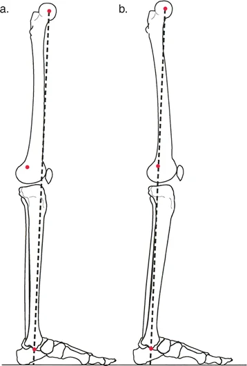
Understanding Mechanical Axis Deviation MAD
The mechanical axis of the lower extremity is the foundational metric of coronal plane alignment. In a normal limb, a line drawn from the center of the femoral head to the center of the ankle plafond should pass directly through, or slightly medial to, the center of the knee joint.
Mechanical Axis Deviation MAD occurs when this line falls outside the normal parameters.
* Varus Deformity: The mechanical axis passes significantly medial to the center of the knee joint. This places excessive compressive forces on the medial compartment.
* Valgus Deformity: The mechanical axis passes lateral to the center of the knee joint, overloading the lateral compartment.
Quantifying the MAD in millimeters is the first step in preoperative planning. However, identifying that a MAD exists does not tell the surgeon where the deformity originates. To locate the source of the deviation, the surgeon must evaluate the joint orientation angles.
Standard Joint Orientation Angles
Joint orientation angles define the relationship between the anatomical or mechanical axis of a bone and its respective joint lines. Deformity analysis requires absolute precision in measuring these angles on full-length, weight-bearing radiographs.
Below is a summary of the critical lower extremity joint orientation angles that every deformity surgeon must commit to memory:
| Angle Acronym | Full Name | Normal Mean Value | Pathological Indicator |
|---|---|---|---|
| mLDFA | Mechanical Lateral Distal Femoral Angle | 87.5 degrees | > 90° indicates distal femur varus; < 85° indicates valgus |
| MPTA | Medial Proximal Tibial Angle | 87.5 degrees | < 85° indicates proximal tibia varus; > 90° indicates valgus |
| LPFA | Lateral Proximal Femoral Angle | 90 degrees | Altered in proximal femoral deformities (coxa vara/valga) |
| mLDTA | Mechanical Lateral Distal Tibial Angle | 89 degrees | Abnormalities indicate distal tibial intra-articular or metaphyseal deformity |
| JLCA | Joint Line Convergence Angle | 0 to 2 degrees | > 2° indicates intra-articular deformity or ligamentous laxity |
By comparing the patient's measured angles against these standard norms, the surgeon can isolate whether the deformity lies in the femur, the tibia, or both, and whether it is metaphyseal or diaphyseal in nature.
Locating the Center of Rotation of Angulation CORA
Once the abnormal bone is identified, the exact apex of the deformity must be pinpointed. This apex is the Center of Rotation of Angulation CORA.
To find the CORA, the surgeon draws the mid-diaphyseal line of the proximal bone segment and the mid-diaphyseal line of the distal bone segment. The exact point where these two lines intersect is the CORA.
- Surgical Pearl: A bone may have a single CORA (unapical deformity) or multiple CORAs (multiapical deformity). In multiapical deformities, correcting the bone at a single level will fail to restore normal anatomy and will likely induce a secondary translation. Each CORA must be respected and addressed in the preoperative plan.
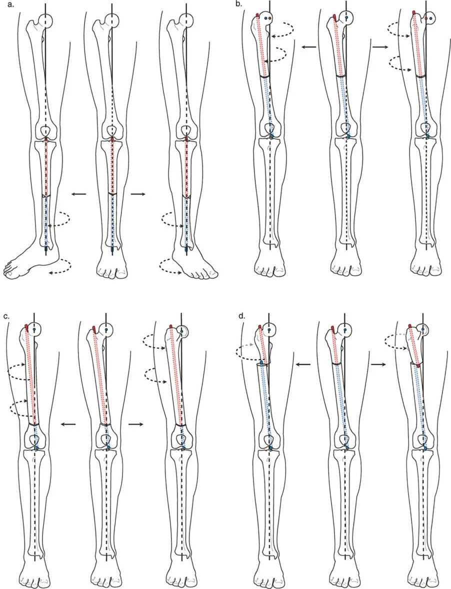
The Three Core Osteotomy Rules
The physical location of the osteotomy cut relative to the CORA, combined with the location of the hinge point ACA, dictates the geometric outcome of the surgery. Dr. Paley formalized this relationship into three immutable osteotomy rules. Mastery of these rules is non-negotiable for reconstructive surgeons.
Osteotomy Rule One Pure Angulation
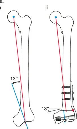
Rule 1: When the osteotomy and the Axis of Correction of Angulation ACA both pass through the CORA, pure angular correction is achieved without any translation of the bone segments.
In this ideal scenario, the anatomical axes of the proximal and distal segments become perfectly collinear. The bone ends remain flush, maximizing bony contact and optimizing the environment for osteogenesis.
* If the ACA is placed on the convex cortex, an opening wedge osteotomy is produced.
* If the ACA is placed on the concave cortex, a closing wedge osteotomy is produced.
* If the ACA is placed in the center of the medullary canal, a neutral wedge (half-open, half-closed) is produced.
Osteotomy Rule Two Angulation with Translation
Rule 2: When the ACA passes through the CORA, but the osteotomy is performed at a different level, angular correction is achieved alongside intentional, calculated translation of the bone segments.
Surgeons frequently utilize Rule 2 when the CORA is located too close to a joint line (epiphyseal or extreme metaphyseal). Cutting directly at the CORA might compromise the joint or leave insufficient bone stock for hardware fixation. By cutting at a distance from the CORA but maintaining the hinge ACA at the CORA, the mechanical axis is perfectly restored. However, the bone ends at the osteotomy site will be translated (offset) relative to one another.
- Surgical Pearl: The magnitude of this intentional translation is directly proportional to the distance between the osteotomy cut and the CORA. The further away the cut, the greater the translation required to maintain mechanical alignment.
Osteotomy Rule Three Unintended Translation
Rule 3: When the osteotomy and the ACA are completely separate from the CORA, a secondary translation deformity is inadvertently created.
This is the classic pitfall of deformity correction. If the surgeon simply cuts the bone and hinges the correction at the osteotomy site (ignoring the true CORA), the proximal and distal mechanical axes will end up parallel but shifted. This creates a zig-zag deformity, altering the mechanical axis of the limb and potentially causing catastrophic joint overloading, even if the bone appears straight to the naked eye.
Biomechanics of Hardware Selection in Deformity Correction
The choice of hardware is inextricably linked to the osteotomy rules and the spatial demands of the deformity. Each class of implant offers distinct biomechanical advantages and limitations.
Internal Plating Systems
Plates are highly favored for definitive stabilization due to patient comfort, lack of pin-tract infections, and rigid internal support. However, standard anatomical plates are designed to fit normal bone. When applied to a corrected deformity, the plate must either be meticulously pre-contoured, or it must be a specialized reconstructive plate designed to accommodate geometric shifts.
Locking plates provide fixed-angle constructs, which are essential for maintaining angular correction in metaphyseal bone where screw purchase may be suboptimal. However, plates offer zero post-operative adjustability. The correction achieved on the operating table is final.
Intramedullary Nailing IMN
Intramedullary nails offer superior load-sharing biomechanics and preserve the periosteal blood supply, promoting rapid union. They are ideal for diaphyseal deformities.
However, standard IM nails naturally want to rest in the center of the medullary canal. If an osteotomy involves intentional translation (Rule 2), a standard nail will force the bone segments back into a collinear position, effectively erasing the translation and ruining the correction. To counter this, surgeons must utilize blocking screws (Poller screws) to artificially narrow the medullary canal and force the nail into the precise trajectory required to maintain the deformity correction.
External Fixation Systems
External fixators, particularly circular frames like the Ilizarov apparatus or hexapod systems (e.g., Taylor Spatial Frame), are the ultimate tools for complex, multiplanar deformities.
Their primary advantage is post-operative adjustability. If the intraoperative correction is slightly off, the frame can be adjusted in the clinic. Furthermore, they allow for gradual correction via distraction osteogenesis, which is mandatory for deformities associated with significant limb length discrepancies or severe soft tissue contractures that cannot tolerate acute correction.
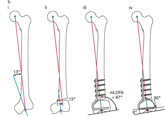
Fixator Assisted Plating FAP for Biplanar Control
One of the most powerful and elegant techniques in modern deformity correction is Fixator-Assisted Plating FAP. While internal plates offer excellent definitive stabilization, achieving the exact desired correction manually before applying the plate is notoriously difficult.
Rationale for Fixator Assisted Techniques
Even highly skilled surgeons frequently experience an error margin of approximately 5 degrees when relying solely on manual reduction, bone clamps, and visual estimation under fluoroscopy. Manual reduction fails to adequately control rotation and frequently loses correction in the sagittal plane while the surgeon focuses on the coronal plane.
FAP bridges the gap between the precise, multiplanar adjustability of external fixation and the convenience and patient tolerance of internal plating.
Step by Step FAP Surgical Workflow
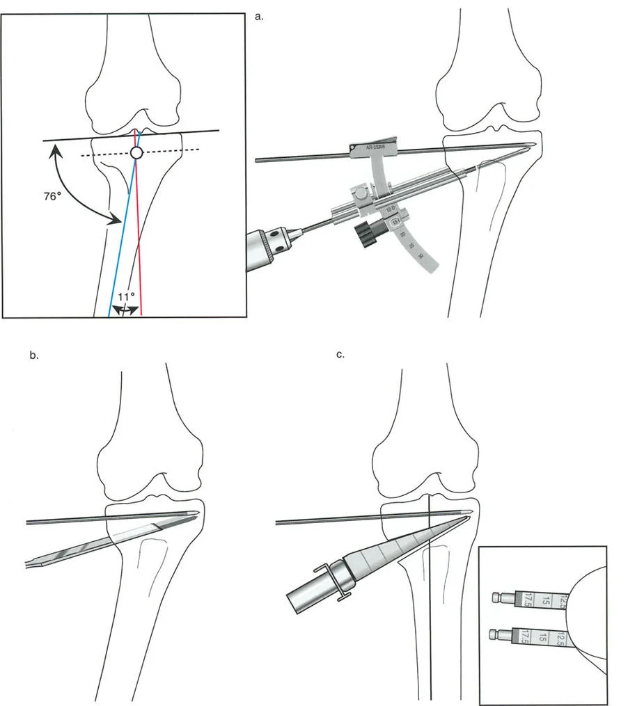
To execute fixator-assisted plating effectively, a rigid external fixator is temporarily applied to the bone segments to act as a highly precise reduction tool.
- Strategic Pin Placement: A monoplanar external fixator is utilized. Two Schanz pins are placed proximally and two pins are placed distally. This provides superior biplanar control. Crucially, each pin must be placed perfectly perpendicular to the mechanical axis of its respective bone segment, not the anatomical axis.
- Frame Configuration: All four pins can be placed in the same plane, or two separate distractors can be utilized (each with one pair of pins in planes perpendicular to each other). Using only one pin above and one below in a single plane is highly discouraged, as it acts as a simple hinge and fails to control or prevent translation in the orthogonal plane.
- Controlled Osteotomy Execution: The bone is exposed, and the osteotomy is performed (typically with a saw or multiple drill holes and an osteotome). The external fixator is then used to dial in the exact correction. The intact cortex (concave or convex, depending on the wedge type) acts as the hinge and the ACA.
- Radiographic Verification: Intraoperative radiography, specifically the Malalignment Test MAT, is utilized to confirm that the desired joint orientation and mechanical axis have been perfectly restored in both the AP and lateral views.
- Definitive Internal Plating: While the external fixator rigidly maintains the flawless correction, the internal plate is contoured (if necessary), applied to the bone, and secured with locking and non-locking screws.
- Fixator Removal: Once the plate is completely secured and the construct is stable, the temporary external fixator pins are removed.
This technique minimizes surgical exposure at the osteotomy site, reduces periosteal stripping, and dramatically increases the angular and rotational accuracy of metaphyseal corrections.
Metaphyseal and Diaphyseal Deformity Management
The anatomical location of the deformity dictates the surgical approach, the type of osteotomy, and the hardware utilized.
Overcoming Limited Fixation Real Estate
Deformities located at the extreme ends of bones (metaphyseal or epiphyseal CORAs) present unique spatial challenges. There is often limited "real estate" for hardware fixation between the osteotomy level and the adjacent physis or articular joint line.
If a surgeon attempts a Rule 1 osteotomy directly at an epiphyseal CORA, there may only be a few millimeters of bone available for proximal or distal screw purchase. This is biomechanically insufficient to withstand the lever-arm forces of the lower extremity, leading to high rates of hardware failure and non-union.
Managing Translation in Metaphyseal Osteotomies
Consequently, surgeons must frequently perform the osteotomy at the metaphyseal-diaphyseal junction, at a safe distance from the CORA, thereby applying Osteotomy Rule 2.
As established, this requires intentional translation at the osteotomy site. Managing this translation is critical. If the bone ends are translated by 15 millimeters, a standard straight plate will not sit flush against the bone. The surgeon must either use an offset plate designed specifically for translated osteotomies or utilize a technique like fixator-assisted nailing FAN, where blocking screws guide the nail to accommodate the offset medullary canal.
- Key Takeaway: Never force translated bone segments to conform to a straight implant. Always force the implant to conform to the geometrically corrected bone segments.
Proximal Femur Reconstructions and Plating
The proximal femur is a highly complex three-dimensional structure. Deformities in this region (coxa vara, coxa valga, retroversion) profoundly impact the mechanical axis of the entire lower limb and the biomechanics of the hip joint.
Traditionally, fixed-angle plates, such as angled blade plates or dynamic condylar screws DCS, have been the preferred hardware in this region. However, these plates are designed with specific, fixed geometries.
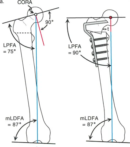
Implant Geometry and the Lateral Proximal Femoral Angle LPFA
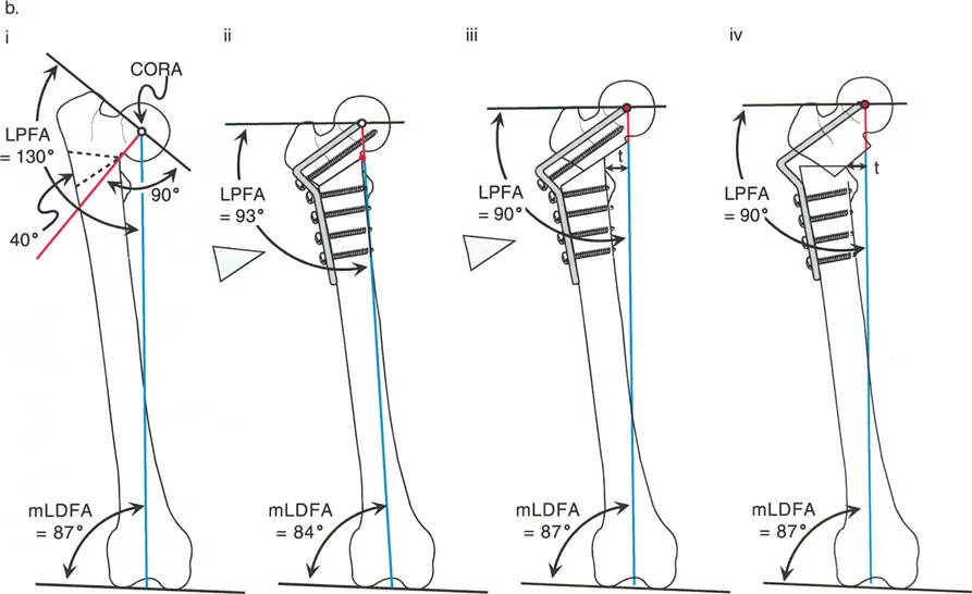
If a standard fixed-angle plate is used for a reconstructive deformity correction without intentional geometric compensation, secondary translation deformities will inevitably arise. The surgeon must understand how the angle of the plate interacts with the native Lateral Proximal Femoral Angle LPFA.
Some specialized plate designs natively incorporate translation into the correction. The proximal femur provides an excellent model for understanding this interaction.
Correcting Valgus Deformity with Varus Osteotomy
Consider a severe valgus deformity of the proximal femur with a preoperative LPFA of 75 degrees (normal LPFA is roughly 90 degrees). To correct this limb to a normal mechanical alignment and restore hip biomechanics, a varus-producing osteotomy is required.
When a standard 90-degree angled blade plate is applied to this valgus femur, the geometry of the plate automatically dictates the correction. If the blade is inserted into the femoral neck parallel to the neck axis, the side plate will sit at a 90-degree angle to the neck.
When the femoral shaft is brought laterally to meet the side plate, the LPFA is automatically corrected from 75 degrees to 90 degrees. However, because the osteotomy is performed below the CORA (which is typically in the femoral head or neck), this represents a Rule 2 osteotomy. The 90-degree plate automatically forces an angulation and a lateral translation of the femoral shaft.
If the surgeon fails to anticipate this lateral translation, the mechanical axis will be shifted laterally, potentially creating a secondary valgus MAD at the knee. To prevent this, the surgeon must calculate the exact amount of translation required and ensure the hardware accommodates it without shifting the overall mechanical axis.
Preoperative Planning and the Malalignment Test MAT
The success of any deformity correction is determined before the patient ever enters the operating room. Meticulous preoperative planning is the hallmark of a master reconstructive surgeon.
Conducting the Preoperative Assessment
Planning begins with high-quality, standing, full-length AP and lateral radiographs of both lower extremities.
- Draw the Axes: The surgeon draws the mechanical and anatomical axes of the femur and tibia.
- Measure the MAD: The mechanical axis deviation is measured in millimeters from the center of the knee joint.
- Calculate Joint Angles: The mLDFA, MPTA, LPFA, and mLDTA are measured and compared to normal values to isolate the deformity.
- Locate the CORA: The intersection of the proximal and distal axes is identified.
- Simulate the Osteotomy: Using digital templating software or traditional paper cutouts, the surgeon simulates the osteotomy based on Paley's Rules, choosing the optimal level for the cut and the hinge point ACA.
- Select the Hardware: The appropriate implant is selected to stabilize the simulated correction, accounting for any necessary translation.
Intraoperative Verification
No matter how perfect the preoperative plan, intraoperative execution must be verified before definitive fixation is applied. This is achieved through the intraoperative Malalignment Test MAT.
With the temporary external fixator holding the correction, the surgeon places an electrocautery cord or a radiopaque alignment rod over the sterile drapes, stretching it from the center of the femoral head to the center of the ankle joint.
Under fluoroscopy, the surgeon verifies that this line passes precisely through the targeted zone of the knee joint (usually the center, or slightly lateral/medial depending on specific reconstructive goals). If the MAT shows residual deviation, the external fixator is adjusted until the alignment is perfect. Only then is the definitive internal hardware applied.
Mastering these principles, rules, and hardware biomechanics allows the orthopedic surgeon to confidently approach the most complex skeletal deformities, transforming debilitating malalignments into functional, biomechanically sound limbs.
!!! info "Academic Resource & Medical Review"
This academic resource was prepared and medically reviewed by Prof. Dr. Mohammed Hutaif, Consultant Orthopedic & Spine Surgeon. It is formulated specifically for medical students, orthopedic residents, and surgeons preparing for high-stakes board examinations (AAOS, FRCS Tr & Orth, Arab Board).
!!! warning "Disclaimer"
The surgical techniques, classifications, and clinical guidelines presented herein are for educational and academic review purposes only. They are not intended to replace institutional protocols or independent clinical judgment.
You Might Also Like