Mastering Orthopedic Deformity Correction: Length, Osteotomies, and Paley's Principles
Key Takeaway
Orthopedic deformity correction involves precise limb length discrepancy measurement using teleoroentgenograms and Paley principles. These include Mechanical Axis Deviation, Joint Orientation Angles, and Center of Rotation of Angulation, which guide osteotomy planning. This ensures successful, functional reconstruction and prevents neurovascular compromise.
Introduction to Length Dynamics in Orthopedic Deformity Correction
In the realm of complex orthopedic reconstruction, the correction of angular deformities is rarely an isolated event. As established by Dr Dror Paley and his fundamental principles of deformity correction, altering the mechanical or anatomic axis of a bone inherently alters its length and the tension on the surrounding soft tissue envelopes. For the orthopedic surgeon, resident, or fellow, mastering the interplay between angular correction and axial length is not just an academic exercise—it is the defining difference between a successful, functional reconstruction and a catastrophic neurovascular compromise.
When planning a deformity correction osteotomy, the surgeon is immediately faced with a critical decision regarding execution. Should the correction be performed acutely utilizing immediate intraoperative realignment and internal fixation, or gradually utilizing principles of distraction histogenesis with external fixators like the Ilizarov apparatus or Taylor Spatial Frame.
This decision cannot be made on intuition. It is strictly dictated by the Center of Rotation of Angulation, the Angulation Correction Axis, the Mechanical Axis Deviation, and the resulting geometric stretch on nerves, arteries, ligaments, and skin.
This comprehensive masterclass delves deep into the biomechanics of length considerations, the precise measurement of Leg Length Discrepancy, the complex geometry of osteotomies based on Paley principles, and the biological neurovascular thresholds that must dictate your surgical planning.
The Foundation of Precision Measuring Leg Length Discrepancy
Before any blade touches bone or any osteotomy is planned, the surgeon must have an immaculate, mathematically precise understanding of the patient preoperative limb lengths. Errors in preoperative measurement compound rapidly when calculating wedge sizes for angular correction, potentially leaving the patient with a newly iatrogenic leg length discrepancy.
Teleoroentgenogram Versus Scanogram
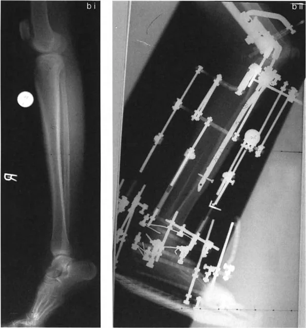
The absolute gold standard for assessing lower extremity deformities is the standing long radiograph, universally known as the teleoroentgenogram. Unlike supine scanograms, this image captures the mechanical axis of the entire lower limb under physiological, weight-bearing conditions. Weight-bearing is non-negotiable because it reveals the true functional impact of joint laxity, cartilage loss, and dynamic deformities that disappear when the patient is supine.
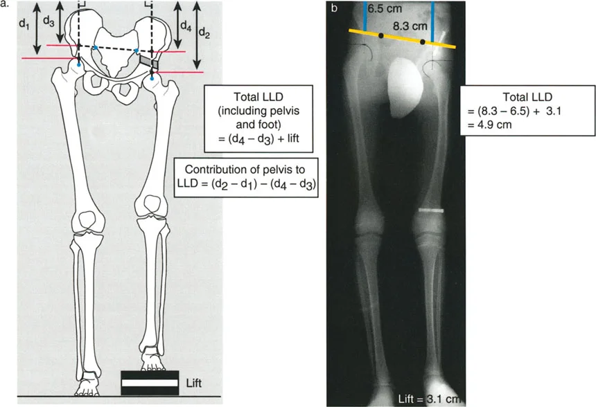
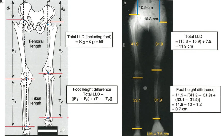
Mathematical precision is required for measurement on a standing long radiograph. The individual femoral and tibial lengths are marked and measured from the joint ends in line with the joint line centers. The total discrepancy, including the foot height difference, is measured as the difference between the distance from the top of the femoral heads to the top of the film.
For example, if the right leg distance to the film top is d2 and the left is d1, the fundamental equation is:
Total Leg Length Discrepancy = (d2 - d1) + lift
Furthermore, the specific contribution of the foot can be isolated. The Foot height difference is calculated as:
Foot Height Difference = Total Discrepancy - [(F1 - F2) + (T1 - T2)]
Clinical Calculation Example for Limb Lengths
Consider a scenario where the total discrepancy is measured at 11.9 cm. The calculation is derived from the initial film measurements and the added lift block. If the total discrepancy is (15.3 - 10.9) + 7.5 = 11.9 cm, the foot height difference can be isolated.
Assuming femoral lengths (F1, F2) and tibial lengths (T1, T2) yield a bone-specific difference of 10 cm, the math unfolds as follows:
Foot height difference = 11.9 - [(41.9 - 31.9) + (33.1 - 31.9)] = 11.9 - 10 = 1.9 cm.
When utilizing lift blocks under the short leg to level the pelvis during the X-ray, the difference between the distances from the femoral heads to the film line, added to the actual height of the lift, equals the true functional discrepancy.
The distinct advantage of the teleoroentgenogram over the traditional supine scanogram is that it inherently includes the foot height difference in the assessment. The specific bone length discrepancy is measured directly between the two femora and the two tibiae. The difference between the total discrepancy and the bone-specific discrepancy reveals the exact foot height contribution.
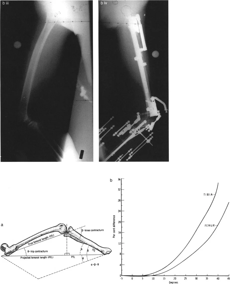
Mitigating Radiographic Magnification Errors
A standard radiograph has a magnification factor of approximately five percent. While this seems negligible, in severe deformities, it alters surgical planning and hardware selection. If a measurement difference between limbs is 30 mm, the total magnification error is 1.5 mm. In cases of massive deformity requiring precise external fixator strut calculations, this error compounds.
Calibration Techniques for Surgical Planning
To mitigate magnification errors, a simple but highly effective modification involves having the patient hold a flexible tube filled with radiopaque fluid across their pelvis. Dilute barium works exceptionally well for this purpose.
The tube is held in a sagging rope fashion. The two fluid levels on either end of the column create a perfect, gravity-dependent horizontal line. This provides a highly accurate reference for measuring femoral head distances irrespective of the X-ray tube angle.
Alternatively, placing a spherical calibration marker of a known diameter (typically 25 mm) at the level of the bone being radiographed allows digital templating software to automatically scale the image, completely neutralizing magnification variables.
Factoring Pelvic Asymmetry into Preoperative Planning
Leg length discrepancy does not stop at the hip joint. Pelvic height anomalies, whether from congenital hypoplasia, prior pelvic osteotomies, or high-energy trauma, can significantly contribute to apparent limb length issues.
To factor pelvic asymmetry into your radiographic planning, you must measure from a stable pelvic reference point rather than relying solely on the tops of the femoral heads.
Step by Step Pelvic Measurement
- Draw a horizontal reference line across the pelvis, proximal to the hip joints.
- Utilize the inferior aspect of the sacroiliac joints or the sacral foramina as reliable bilateral landmarks. The iliac crests and ischial tuberosities are often unreliable due to asymmetric hypoplasia.
- Extend this reference line across the tops of the femoral heads.
- The distance from this line above each femoral head to the film edge is measured and added to the baseline limb measurements to determine the true pelvic contribution to the discrepancy.
Paley Principles of Deformity Correction
Dr Dror Paley revolutionized orthopedic surgery by introducing a systematic, reproducible, and mathematically sound approach to deformity analysis. To master length and deformity correction, the surgeon must be fluent in the language of mechanical axes and joint orientation angles.
Mechanical Axis Deviation and Joint Orientation Angles
The mechanical axis of the lower extremity is a straight line drawn from the center of the femoral head to the center of the ankle joint. In a normal limb, this line passes slightly medial to the center of the knee joint. The distance from the center of the knee to this line is the Mechanical Axis Deviation.
When evaluating a deformity, the surgeon must determine if the deviation is caused by a femoral deformity, a tibial deformity, or joint laxity. This is achieved by measuring the Joint Orientation Angles.
These angles measure the relationship between the mechanical or anatomic axis of a bone and its respective joint line.
| Joint Orientation Angle | Abbreviation | Normal Value Range |
|---|---|---|
| Mechanical Lateral Distal Femoral Angle | mLDFA | 85 to 90 degrees (Avg 88) |
| Medial Proximal Tibial Angle | MPTA | 85 to 90 degrees (Avg 87) |
| Lateral Distal Tibial Angle | LDTA | 86 to 92 degrees (Avg 89) |
| Joint Line Convergence Angle | JLCA | 0 to 2 degrees |
By comparing the patient specific angles to these normative values, the surgeon can pinpoint exactly which bone segment is responsible for the Mechanical Axis Deviation. If the mLDFA is 95 degrees, the distal femur is in varus. If the MPTA is 80 degrees, the proximal tibia is in varus.
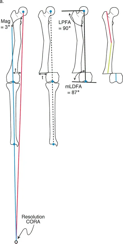
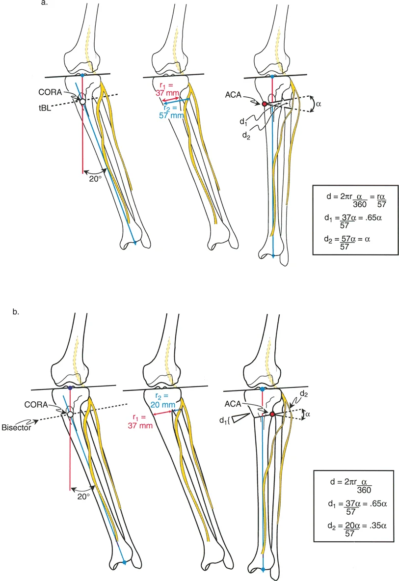
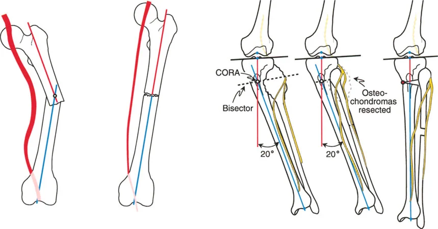
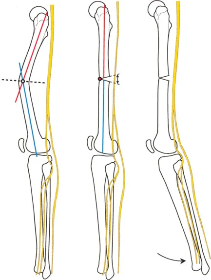
Center of Rotation of Angulation
Once the abnormal bone segment is identified, the exact apex of the deformity must be located. This apex is known as the Center of Rotation of Angulation.
To find the Center of Rotation of Angulation, the surgeon draws the proximal mechanical axis line and the distal mechanical axis line of the deformed bone segment. The point where these two lines intersect is the Center of Rotation of Angulation.
Understanding this point is the absolute cornerstone of surgical planning. The relationship between the osteotomy cut, the Center of Rotation of Angulation, and the Angulation Correction Axis dictates whether the bone will simply angulate, or if it will translate and alter the length of the limb.
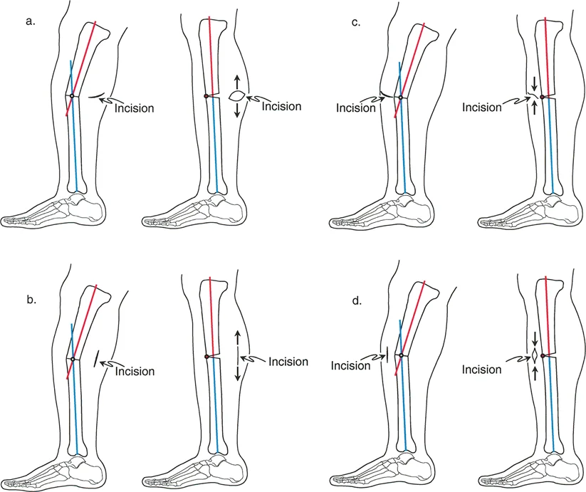
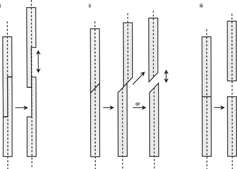
The Three Osteotomy Rules
Paley formulated three distinct osteotomy rules that govern the geometric behavior of bone segments during correction. Mastering these rules is mandatory for any orthopedic surgeon performing reconstructive procedures.
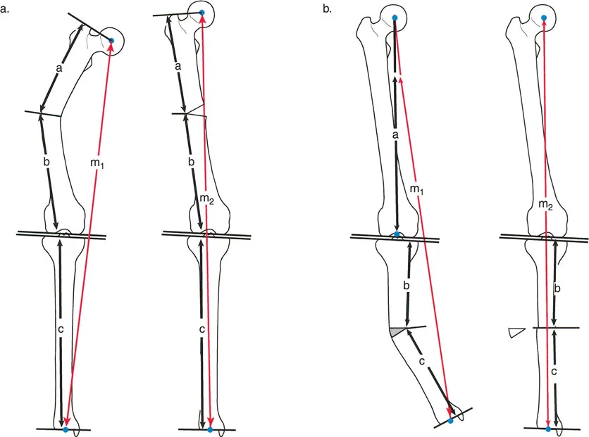
Osteotomy Rule One
When the osteotomy line and the Angulation Correction Axis both pass through the Center of Rotation of Angulation, the bone ends will angulate without any translation.

This is the most stable and anatomically pure form of correction. The mechanical axis is fully restored, and the bone ends remain perfectly aligned. This is the ideal scenario for a simple opening or closing wedge osteotomy performed at the apex of the deformity.
Osteotomy Rule Two
When the osteotomy line is placed at a different level than the Center of Rotation of Angulation, but the Angulation Correction Axis remains at the Center of Rotation of Angulation, the bone ends will angulate and translate.
This rule is highly utilized in clinical practice. Often, the anatomical Center of Rotation of Angulation is located at the level of the joint line or in an area of poor bone stock (such as the metaphyseal-diaphyseal junction). By placing the osteotomy in healthier bone (metaphysis) but hinging the correction around the true Center of Rotation of Angulation, the surgeon achieves perfect mechanical axis realignment. The resulting translation is an expected and necessary geometric phenomenon to restore the axis.
Osteotomy Rule Three
When the osteotomy line and the Angulation Correction Axis are both placed outside the Center of Rotation of Angulation, the correction will result in a secondary translation deformity.
This rule highlights a common pitfall in inexperienced hands. If the surgeon hinges the bone at the osteotomy site rather than at the true deformity apex, the mechanical axis will not be restored, resulting in a zigzag deformity. This creates unintended sheer forces across the adjacent joints and leaves the patient with persistent Mechanical Axis Deviation.
Acute Versus Gradual Deformity Correction
With the geometry of the deformity mapped, the surgeon must decide on the method of execution. The choice between acute and gradual correction is influenced by the magnitude of the deformity, the presence of leg length discrepancy, and the elasticity of the surrounding soft tissues.
Indications for Acute Correction
Acute correction involves performing the osteotomy, immediately realigning the limb to the planned parameters, and securing it with internal fixation such as plates, intramedullary nails, or acute external fixation.

Acute correction is generally indicated for:
* Angular deformities less than 15 to 20 degrees.
* Leg length discrepancies requiring less than 1.5 to 2.0 cm of acute lengthening.
* Rotational deformities less than 15 degrees.
* Patients with highly compliant soft tissue envelopes.
* Situations where patient compliance with a gradual external fixator protocol is questionable.
The primary advantage of acute correction is patient comfort and immediate mechanical stability. However, the surgeon must be acutely aware of the stretch placed on neurovascular structures.
Indications for Gradual Correction
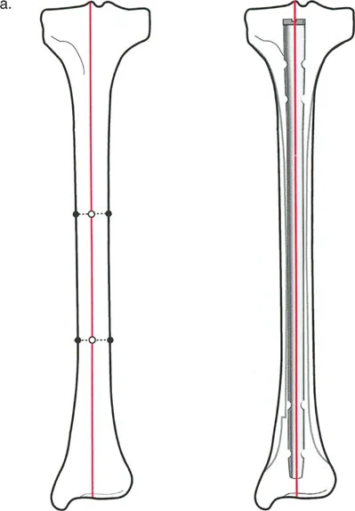
Gradual correction utilizes the biological miracle of distraction osteogenesis. An external fixator is applied, an osteotomy is performed (typically a corticotomy to preserve endosteal blood supply), and after a latency period, the bone is gradually distracted.
Gradual correction is the treatment of choice for:
* Large angular deformities exceeding 20 degrees.
* Significant leg length discrepancies requiring more than 2.0 cm of lengthening.
* Complex multiplanar deformities (simultaneous angulation, rotation, and translation).
* Patients with poor soft tissue envelopes, such as those with severe scarring from prior trauma or burns.
* Cases with high risk for neurovascular compromise.
The gradual nature of the correction allows the nerves, vessels, muscles, and skin to undergo distraction histogenesis alongside the bone, safely accommodating massive changes in limb geometry.
Biomechanics of Osteotomies and Soft Tissue Tension
The manipulation of bone geometry cannot be separated from the soft tissue envelope. When an opening wedge osteotomy is performed, the bone is essentially lengthened on the convex side of the deformity. This lengthening applies immediate tension to the structures bridging that gap.
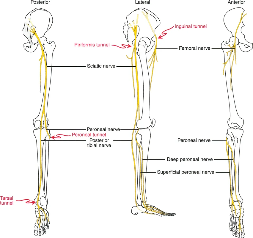
Neurovascular Thresholds in Acute Correction
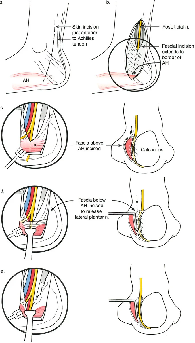
The most notorious structure at risk during lower extremity deformity correction is the common peroneal nerve. When correcting a severe valgus deformity of the proximal tibia (such as a large opening wedge medial high tibial osteotomy), the mechanical axis is shifted medially, and the lateral soft tissue structures are placed under immense stretch.
Surgical Pearls for Nerve Protection:
* Prophylactic Decompression: In acute corrections of valgus deformities exceeding 10 to 15 degrees, a prophylactic common peroneal nerve decompression at the fibular neck is strongly recommended.
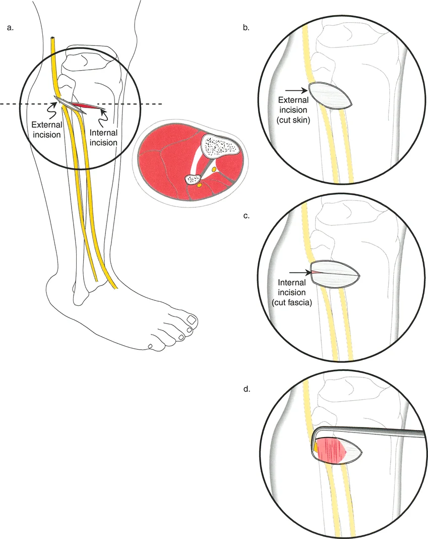
* Fasciotomy: Acute lengthening or large angular corrections increase intracompartmental pressures. Prophylactic anterior and lateral compartment fasciotomies should be considered to prevent acute compartment syndrome.
* Positioning: Postoperatively, keeping the knee in slight flexion can relieve tension on the peroneal nerve and popliteal artery until the soft tissues accommodate the new skeletal length.
Distraction Osteogenesis Principles
When opting for gradual correction, the surgeon must adhere to the biological principles of distraction osteogenesis established by Ilizarov.
- Latency Period: After the corticotomy, a resting phase of 5 to 7 days is required. This allows the initial fracture hematoma to form and mesenchymal stem cells to populate the gap.
- Rate of Distraction: The optimal rate of distraction is 1.0 mm per day.
- Rhythm of Distraction: The 1.0 mm daily rate should be divided into multiple smaller increments. Typically, this is achieved by distracting 0.25 mm four times a day. High-frequency, low-magnitude distraction produces superior regenerate bone and minimizes soft tissue trauma.
- Consolidation Phase: Once the desired length and alignment are achieved, the fixator remains in place while the regenerate bone mineralizes. The consolidation phase is typically twice as long as the distraction phase.
Advanced Preoperative Planning Workflows
Modern deformity correction relies heavily on systematic preoperative planning. The Reverse Planning Method and the Malalignment Test are essential workflows for the reconstructive surgeon.
The Malalignment Test
The Malalignment Test is a systematic evaluation of the standing teleoroentgenogram to identify the exact source of mechanical axis deviation.
- Draw the mechanical axis of the entire limb.
- Evaluate the joint line convergence angle. If it is greater than 2 degrees, joint laxity is contributing to the deformity.
- Measure the mLDFA and MPTA. Compare them to the standard normative values.
- If the mLDFA is abnormal, the femur is deformed. If the MPTA is abnormal, the tibia is deformed. If both are abnormal, a double-level osteotomy may be required.
Digital Templating and Deformity Analysis
While manual drawing on printed radiographs remains a valuable educational tool, modern practice utilizes advanced digital templating software. These programs allow the surgeon to simulate multiple osteotomy levels, visualize the resulting translation, and calculate the exact dimensions of opening or closing wedges.
When planning an external fixator application, such as a Taylor Spatial Frame, the software requires precise input of the deformity parameters (angulation, translation, rotation, and length) relative to a reference ring. The software then generates a daily strut adjustment schedule for the patient.
Key Takeaways for the Reconstructive Surgeon
- Never plan a deformity correction without a high-quality, weight-bearing standing long radiograph.
- Always account for magnification errors and pelvic asymmetry when calculating leg length discrepancy.
- The Center of Rotation of Angulation dictates your osteotomy placement. Respect the three osteotomy rules to avoid secondary translation deformities.
- Respect the soft tissue envelope. Acute corrections have strict neurovascular limits. When in doubt, utilize gradual distraction osteogenesis.
- Prophylactic nerve decompressions and fasciotomies are essential tools in the deformity surgeon armamentarium.
Mastering length and deformity correction is a lifelong pursuit of biomechanical perfection. By strictly adhering to Paley principles, respecting the biological limits of soft tissues, and executing precise preoperative planning, the orthopedic surgeon can consistently achieve outstanding functional outcomes in even the most complex reconstructive scenarios.
!!! info "Academic Resource & Medical Review"
This academic resource was prepared and medically reviewed by Prof. Dr. Mohammed Hutaif, Consultant Orthopedic & Spine Surgeon. It is formulated specifically for medical students, orthopedic residents, and surgeons preparing for high-stakes board examinations (AAOS, FRCS Tr & Orth, Arab Board).
!!! warning "Disclaimer"
The surgical techniques, classifications, and clinical guidelines presented herein are for educational and academic review purposes only. They are not intended to replace institutional protocols or independent clinical judgment.
You Might Also Like