Mastering Limb Length Discrepancy: Paley Principles for Orthopedic Deformity Correction
Key Takeaway
Limb length discrepancy (LLD) is a measurable difference between paired limbs, evaluated clinically and radiographically. Paley Principles provide a systematic framework for orthopedic deformity correction, focusing on mechanical axis deviation and joint orientation angles for precise surgical planning and optimal outcomes.
Introduction to Limb Length Considerations in Orthopedic Surgery
In the highly specialized realm of orthopedic deformity correction, the precise evaluation and management of limb length discrepancy form the bedrock of successful surgical outcomes. Length discrepancy of a bone is formally considered a deformity when there is a measurable difference in length between two paired limbs, or when there is a significant deviation from the normal expected length of a bone for a specific age, gender, and demographic.
For orthopedic surgeons in training, residents, and fellows, mastering the principles of limb length discrepancy requires moving far beyond simple tape measurements. It demands a profound, three dimensional understanding of lower extremity biomechanics, the Paley principles of deformity correction, and the nuanced, patient specific decision making between gradual versus acute correction methodologies.
This comprehensive masterclass deconstructs the critical components of length considerations. It provides an exhaustive, high yield framework for evaluating limb length discrepancy, understanding its profound biomechanical implications on the kinetic chain, and planning flawless surgical interventions using standardized deformity analysis.
Defining the Parameters of Limb Length Discrepancy
Limb length discrepancy is not a monolithic or isolated diagnosis. It is a complex, multi dimensional deformity defined fundamentally by two distinct parameters of magnitude and direction. Failing to account for both inevitably leads to surgical malalignment, altered joint kinematics, and poor patient outcomes.
Magnitude and Direction in Deformity
Magnitude refers to the absolute quantitative difference in length between one side and the contralateral side. Leg length is either pathologically increased or decreased in one limb relative to the other. Pathological increases are often seen in conditions such as hemihypertrophy or vascular malformations like Klippel Trenaunay syndrome. Pathological decreases are far more common and arise from congenital short femur, fibular hemimelia, post traumatic physeal growth arrest, or osteomyelitis.
Direction refers to the vector of the discrepancy. It defines whether the primary issue is shortening or overgrowth, and critically, how this length discrepancy interacts with concomitant angular or translational deformities. A bone is rarely just short. It is often short and bowed, presenting with varus or valgus angulation, and procurvectum or recurvatum in the sagittal plane. Correcting length without addressing the directional deformity vector will exacerbate joint malorientation.
Unilateral Versus Bilateral Discrepancies
When an opposite, normal limb segment is available for comparison, the measurement is straightforward. It is the delta between the length of the normal side and the affected side. However, the diagnostic complexity increases exponentially when both limbs are affected.
Conditions such as rhizomelic dwarfism affecting the proximal segment like achondroplasia, or mesomelic dwarfism affecting the middle segment like dyschondrosteosis present bilateral shortening. In these scenarios, the comparison cannot be made contralaterally. Instead, the surgeon must compare the patient absolute bone lengths and the proportion of the femur to the tibia against standardized normative data for the population of that specific age.
The Paley Multiplier Method for Growth Prediction
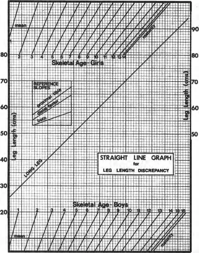
For pediatric patients, calculating the discrepancy at skeletal maturity is vastly more important than the current discrepancy. While older methods like the Anderson, Green, and Messner growth charts or the Moseley straight line graph are historically significant, the Paley Multiplier Method is the modern gold standard for orthopedic surgeons.
By multiplying the current length of the bone or the current discrepancy by a specific age and gender matched coefficient, surgeons can rapidly and accurately predict the ultimate discrepancy at skeletal maturity. This dictates the timing of epiphysiodesis or lengthening procedures.
Clinical Pearls for the Multiplier Method
* The multiplier is independent of the percentile of the child.
* It assumes that the inhibition of growth in the affected limb remains constant over time.
* The formula is simply calculated as Length at Maturity equals Current Length multiplied by the Multiplier.
* Multiplier values are readily available via mobile applications, ensuring rapid clinic based calculations without complex graphing.
Clinical Evaluation of Limb Length Discrepancy
Before any radiographic imaging is ordered, a meticulous clinical examination must be performed. Clinical evaluation dictates the functional impact of the discrepancy, assesses joint contractures, and guides the interpretation of subsequent radiographs.
The Functional Standing Block Test
There are numerous methodologies to measure length discrepancy clinically, but the most functionally relevant is the standing block test. Most patients possess a highly attuned proprioceptive sense of their discrepancy. By having the patient stand barefoot on a firm, level surface and placing calibrated wooden or plastic blocks of known thicknesses under the shorter limb, the surgeon can accurately assess the functional discrepancy.
The height of the lift required to level the pelvis, specifically aligning the iliac crests and posterior superior iliac spines, and make the patient feel as though their limbs are of equal length represents the clinically significant discrepancy.
It is critical to note that long standing discrepancies often lead to compensatory mechanisms, including fixed pelvic tilt, equinus contracture of the ankle, and compensatory lumbar scoliosis. In adult patients who have lived with a discrepancy for decades, achieving mathematical equality may paradoxically make them feel as though the newly lengthened limb is too long. The block test is paramount because it reveals the tolerable correction, which may differ significantly from the radiographic correction.
True Limb Length Discrepancy Measurement
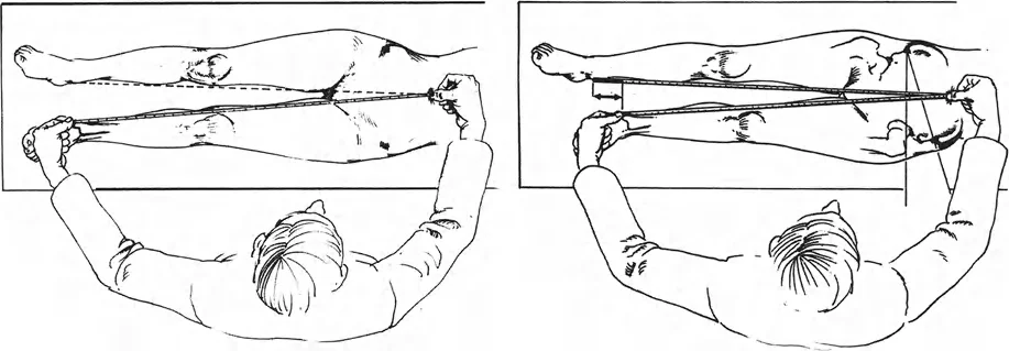
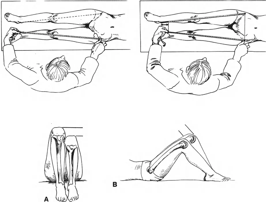
Clinical measurements of leg length are traditionally obtained using a flexible tape measure, a technique popularized by Hoppenfeld.
The standard method for determining True Limb Length Discrepancy involves measuring from a fixed bony landmark on the pelvis to a fixed bony landmark on the distal limb. The most reliable points are the anterosuperior iliac spine to the tip of the medial malleolus.
When performing this measurement, both bony landmarks are best palpated from their distal side to ensure consistency. The length measured between the anterosuperior iliac spine and the medial malleolus provides a baseline, though it is highly susceptible to user error, particularly in obese patients or those with severe pelvic obliquity. Therefore, radiographic confirmation is always mandatory prior to surgical intervention.
Apparent Limb Length Discrepancy Measurement
Apparent limb length discrepancy is measured from a non fixed point, typically the umbilicus, to the medial malleolus. This measurement is crucial because it accounts for pelvic obliquity and spinal deformity. If the true limb length is equal bilaterally, but the apparent limb length is unequal, the surgeon must investigate the spine and pelvis for the source of the asymmetry, such as a fixed adduction contracture of the hip or a scoliotic curve.
Core Paley Principles of Deformity Correction
Dr Dror Paley revolutionized orthopedic deformity correction by introducing a systematic, reproducible, and biomechanically sound framework for evaluating and treating complex limb deformities. Mastering these principles is non negotiable for the modern orthopedic surgeon.
Mechanical Axis Deviation and the Malalignment Test
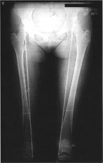
The foundation of lower extremity deformity analysis is the Mechanical Axis Deviation. The mechanical axis of the lower extremity is a straight line drawn from the center of the femoral head to the center of the ankle joint tibial plafond. In a normally aligned limb, this line should pass slightly medial to the center of the knee joint, specifically 8 millimeters medial to the midline of the knee.
The Malalignment Test is the first step in radiographic evaluation using a standing full length anteroposterior radiograph.
1. Draw the mechanical axis line from the femoral head to the ankle.
2. Observe where this line intersects the knee joint.
3. If the line passes medial to the center of the knee by more than 15 millimeters, the patient has a varus deformity.
4. If the line passes lateral to the center of the knee, the patient has a valgus deformity.
The distance from the center of the knee to the mechanical axis line is the Mechanical Axis Deviation. Identifying an abnormal Mechanical Axis Deviation confirms that a deformity exists, prompting the surgeon to evaluate individual joint orientation angles to localize the exact source of the pathology.
Joint Orientation Angles
To localize a deformity to the femur or the tibia, the surgeon must measure the joint orientation angles. These angles define the relationship between the mechanical or anatomic axes of the bones and their respective joint lines.
The nomenclature developed by Paley is highly specific. It uses a prefix indicating medial or lateral, a prefix indicating mechanical or anatomic, the bone in question, and the joint in question.
Standard Joint Orientation Angles Table
| Angle Designation | Full Name | Normal Value Range | Average Value |
|---|---|---|---|
| mLPFA | Mechanical Lateral Proximal Femoral Angle | 85 to 95 degrees | 90 degrees |
| mLDFA | Mechanical Lateral Distal Femoral Angle | 85 to 90 degrees | 87 degrees |
| MPTA | Medial Proximal Tibial Angle | 85 to 90 degrees | 87 degrees |
| mLDTA | Mechanical Lateral Distal Tibial Angle | 86 to 92 degrees | 89 degrees |
| JLCA | Joint Line Convergence Angle | 0 to 2 degrees | 0 degrees |
By comparing the patient measured angles to these normative values, the surgeon can definitively state whether a varus or valgus deformity is originating from the distal femur, the proximal tibia, or within the knee joint itself due to ligamentous laxity as indicated by an abnormal Joint Line Convergence Angle.
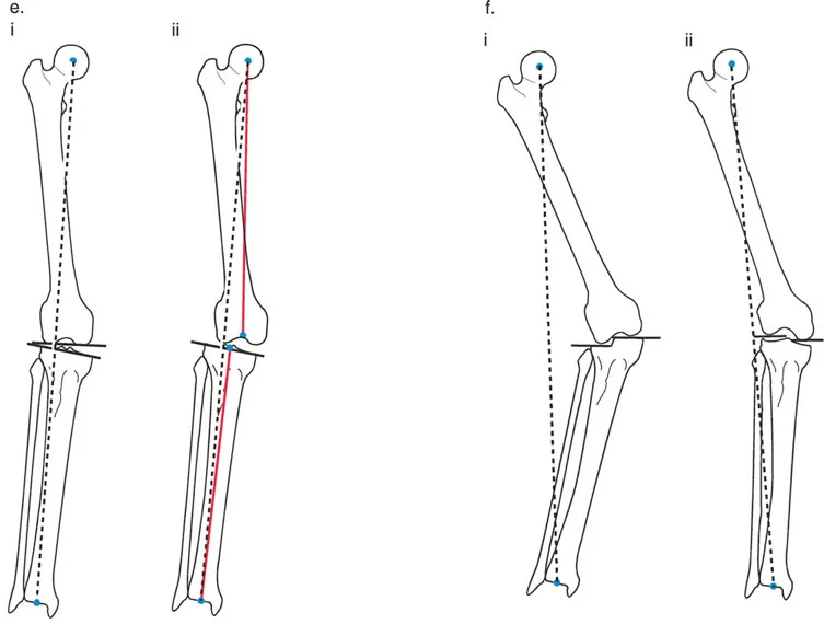
Center of Rotation of Angulation
Once the deformed bone is identified, the exact apex of the deformity must be pinpointed. This apex is known as the Center of Rotation of Angulation.
The Center of Rotation of Angulation is found by drawing the mechanical or anatomic axis of the proximal segment of the deformed bone and the corresponding axis of the distal segment. The point where these two lines intersect is the Center of Rotation of Angulation.
Understanding the Center of Rotation of Angulation is the most critical step in preoperative planning. The relationship between the Center of Rotation of Angulation, the osteotomy site, and the axis of correction of angulation dictates whether the bone will heal in perfect alignment or suffer from iatrogenic translation.
The Three Osteotomy Rules of Paley
Dr Paley codified the biomechanical behavior of bone correction into three fundamental osteotomy rules. These rules govern how a bone segment will move when cut and angled, depending on where the hinge or axis of correction is placed relative to the Center of Rotation of Angulation.
Osteotomy Rule One
When the osteotomy and the axis of correction of angulation both pass through the Center of Rotation of Angulation, the bone will undergo pure angulation without any translation.
This is the ideal scenario for deformity correction. The mechanical axis of the proximal segment and the distal segment will perfectly realign. The bone ends at the osteotomy site will remain in excellent contact, facilitating rapid bone healing and minimizing the risk of nonunion.
Osteotomy Rule Two
When the axis of correction of angulation passes through the Center of Rotation of Angulation, but the osteotomy is performed at a different level away from the Center of Rotation of Angulation, the bone will undergo angulation with expected translation.
This rule is frequently utilized in clinical practice when the Center of Rotation of Angulation is located near a joint line where an osteotomy would be unsafe or compromise fixation. By placing the hinge at the Center of Rotation of Angulation but cutting the bone further down the diaphysis, the mechanical axes will still perfectly realign. However, the bone ends at the osteotomy site will translate. This creates a step off at the cortex, which is acceptable and will remodel over time, provided the overall mechanical axis is restored.
Osteotomy Rule Three
When the axis of correction of angulation and the osteotomy are both placed away from the Center of Rotation of Angulation, the bone will undergo angulation, but the mechanical axes will not align, resulting in a secondary translation deformity.
This is generally considered an error in preoperative planning. If the hinge is not placed on the Center of Rotation of Angulation, correcting the angular deformity will inadvertently create a translational deformity, shifting the mechanical axis away from the center of the joint. This iatrogenic malalignment can lead to rapid joint degeneration. Rule Three is only intentionally used when a surgeon needs to simultaneously correct a pre existing angular and translational deformity.
Preoperative Planning for Deformity Correction
Flawless surgical execution is impossible without meticulous preoperative planning. The process of deformity analysis must be systematic, reproducible, and documented thoroughly before the patient enters the operating room.
Step by Step Guide to Radiographic Planning
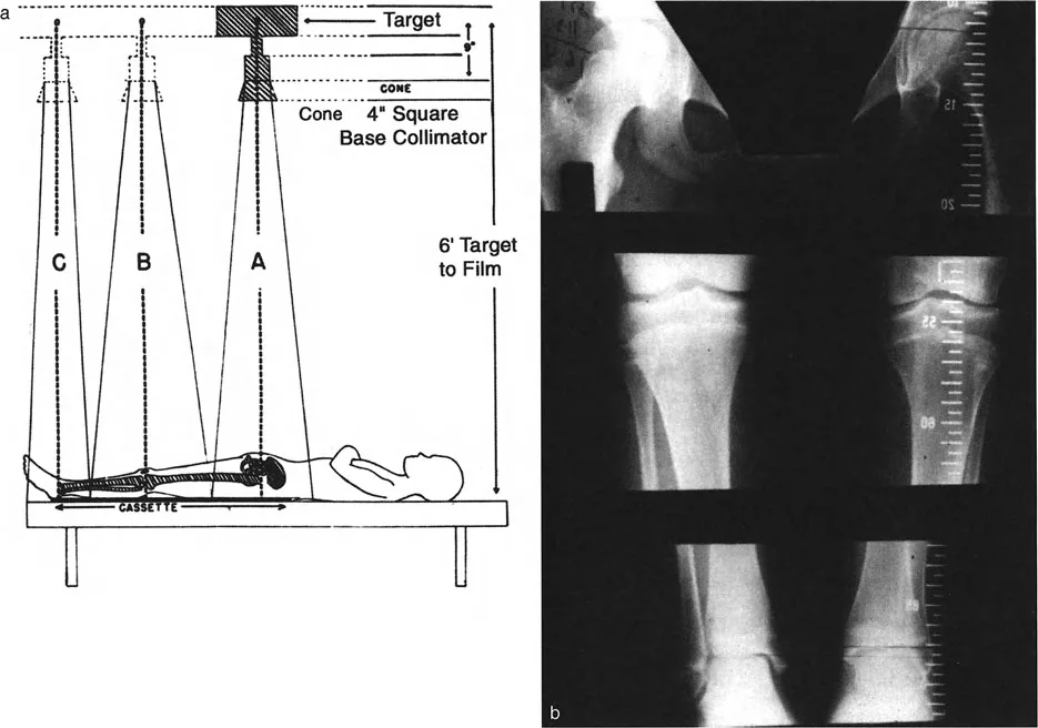
- Obtain Standardized Imaging Acquire standing, full length, weight bearing anteroposterior and lateral radiographs of both lower extremities. Ensure the patellae are facing strictly forward to control for rotational variations.
- Perform the Malalignment Test Draw the mechanical axis from the center of the femoral head to the center of the tibial plafond. Measure the Mechanical Axis Deviation relative to the center of the knee.
- Measure Joint Orientation Angles Calculate the mechanical Lateral Distal Femoral Angle and the Medial Proximal Tibial Angle. Identify which bone is responsible for the Mechanical Axis Deviation.
- Locate the Center of Rotation of Angulation Draw the proximal and distal mechanical axes of the deformed bone. Mark their intersection as the Center of Rotation of Angulation.
- Determine the Magnitude of Correction Measure the angle between the proximal and distal axes. This is the exact degree of angular correction required.
- Select the Osteotomy Site Choose an osteotomy level based on bone quality, soft tissue envelope, and the location of the Center of Rotation of Angulation. Apply Paley Osteotomy Rules to determine if translation will occur.
- Plan the Fixation Construct Decide between acute correction with internal fixation like plates or intramedullary nails, or gradual correction using a circular external fixator based on the magnitude of deformity and soft tissue compliance.
Surgical Execution and Fixation Strategies
The choice of fixation and the method of correction depend heavily on the magnitude of the deformity, the presence of limb length discrepancy, and the condition of the surrounding soft tissues.
Acute Versus Gradual Correction
Acute correction involves performing the osteotomy, manually correcting the deformity in the operating room, and stabilizing the bone with internal fixation such as a locking plate or an intramedullary nail. This is highly preferred for isolated angular deformities of moderate magnitude without significant limb shortening. It offers immediate patient comfort and avoids the pin tract infections associated with external frames.
Gradual correction relies on the principles of distraction osteogenesis pioneered by Gavriil Ilizarov. It is indicated for large magnitude angular deformities, severe limb length discrepancies, or when the soft tissue envelope cannot tolerate acute stretching. The bone is osteotomized corticotomy, and after a latency phase of five to seven days, the bone segments are gradually pulled apart at a rate of approximately one millimeter per day. This tension stress allows for the simultaneous regeneration of bone, nerves, vessels, and skin.
Frame Application and Biomechanics
When gradual correction is selected, circular external fixators are the implants of choice. Traditional Ilizarov frames use rings connected by threaded rods and hinges. The hinges must be meticulously placed exactly on the axis of correction of angulation to obey Paley Osteotomy Rules.
Modern deformity correction heavily utilizes hexapod circular fixators, such as the Taylor Spatial Frame. These devices use six telescopic struts connecting two rings, operating on the principles of a Stewart platform. By inputting the deformity parameters, the mounting parameters, and the strut lengths into a specialized software program, the computer generates a daily prescription for the patient to turn the struts.
Surgical Pearls for Hexapod Frames
* The software allows for simultaneous correction of angulation, translation, rotation, and length in all six degrees of freedom.
* The virtual hinge can be placed anywhere in space, allowing the surgeon to easily obey Osteotomy Rule One or Two without complex mechanical hinge assembly.
* Orthogonal mounting of the reference ring to the reference bone segment is critical. Any mounting error will result in residual deformity if not accounted for in the software.
Conclusion and Future Directions in Deformity Correction
Mastering limb length discrepancy and deformity correction requires a rigorous dedication to biomechanical principles. The transition from simple clinical assessments to the sophisticated, three dimensional geometric analysis championed by Dr Dror Paley represents a paradigm shift in orthopedic surgery.
By strictly adhering to the evaluation of magnitude and direction, understanding the profound implications of the Center of Rotation of Angulation, and applying the three osteotomy rules, surgeons can predictably restore mechanical alignment and joint kinematics.
The future of deformity correction continues to evolve with the advent of fully implantable, motorized intramedullary lengthening nails. These devices eliminate the need for external fixators in many patients, drastically reducing complication rates and improving psychological outcomes. However, whether utilizing a computer assisted hexapod frame or a magnetic lengthening nail, the foundational Paley principles remain absolute. Accurate preoperative planning, respect for the soft tissue envelope, and precise execution of the mechanical axis restoration will forever remain the ultimate standard of care in orthopedic deformity correction.
!!! info "Academic Resource & Medical Review"
This academic resource was prepared and medically reviewed by Prof. Dr. Mohammed Hutaif, Consultant Orthopedic & Spine Surgeon. It is formulated specifically for medical students, orthopedic residents, and surgeons preparing for high-stakes board examinations (AAOS, FRCS Tr & Orth, Arab Board).
!!! warning "Disclaimer"
The surgical techniques, classifications, and clinical guidelines presented herein are for educational and academic review purposes only. They are not intended to replace institutional protocols or independent clinical judgment.
You Might Also Like