Mastering Complex Deformity: Advanced Paley Principles for Angulation-Rotation Correction
Key Takeaway
Simultaneous angulation-rotation deformity correction uses advanced Paley Principles. An inclined osteotomy, guided by the Center of Rotation of Angulation, mathematically couples angular and rotational corrections in a single maneuver. This preserves bone and maximizes healing potential.
Introduction to Complex Three Dimensional Deformity Correction
In the specialized realm of orthopedic deformity correction, resolving a uniplanar deformity such as pure varus or pure valgus is largely a straightforward geometric exercise. However, clinical reality is rarely so accommodating. When a patient presents with a combined angulation and rotation deformity, a bone that is simultaneously bent and twisted, the biomechanical and spatial complexity increases exponentially.
Historically, orthopedic surgeons attempted to correct these complex three-dimensional malalignments through staged procedures or cumbersome multi-planar wedge osteotomies. These archaic approaches were fraught with complications. Removing multiple wedges of bone often resulted in severe leg length discrepancies, secondary translational deformities, and compromised bone healing due to poor cortical contact and devascularization. Furthermore, attempting to correct rotation after angulation often led to catastrophic soft tissue tension and joint subluxation.
The paradigm shifted entirely when Dr. Dror Paley introduced a mathematically sound, highly reproducible framework based on the Center of Rotation of Angulation and the mechanical axis. By understanding the intricate spatial relationship between the axis of correction of angulation and the osteotomy plane, modern surgeons can execute a single, elegantly calculated cut known as the inclined osteotomy. This single maneuver mathematically couples the angular and rotational corrections, resolving both malalignments simultaneously while preserving bone stock and maximizing healing potential.
This comprehensive masterclass is designed specifically for orthopedic surgeons in training, fellows, and advanced deformity specialists. We will delve deep into the biomechanics, preoperative radiographic templating, and precise surgical execution of simultaneous angulation and rotation deformity correction. By utilizing these principles, you will be equipped to transform abstract trigonometric concepts into practical, high-yield surgical strategies in the operating room.
Foundational Paley Principles Setting the Stage
Before one can master the nuances of complex three-dimensional corrections, an ironclad understanding of Dr. Paley’s foundational two-dimensional principles is mandatory. The correction of any lower extremity deformity begins not with the saw, but with a meticulous analysis of the limb mechanical axis and joint orientation angles. These principles form the bedrock of the Paley method.
Understanding Mechanical Axis Deviation
The mechanical axis of the lower extremity is defined by a straight line drawn from the center of the femoral head to the center of the ankle joint at the tibial plafond. In a normally aligned, healthy limb, this line passes slightly medial to the exact center of the knee joint, approximately eight millimeters medial to the midpoint of the tibial plateau.
When a structural deformity exists within the femur or tibia, this mechanical axis line shifts away from the center of the knee. This shift is termed Mechanical Axis Deviation.
- Medial Mechanical Axis Deviation Indicates a varus deformity, leading to medial compartment overload, stretching of the lateral collateral ligament complex, and early onset osteoarthritis.
- Lateral Mechanical Axis Deviation Indicates a valgus deformity, leading to lateral compartment overload, medial collateral ligament attenuation, and patellofemoral tracking pathology.
Correcting the mechanical axis deviation to restore normal joint contact forces and optimize load distribution is the ultimate, overarching goal of any lower extremity osteotomy.
Standardized Joint Orientation Angles
To locate the exact apex of a deformity within a bone, surgeons cannot simply estimate or eyeball the curve. They must rely on standardized, population-derived joint orientation angles. These angles define the normal relationship between the mechanical axis and the articular surfaces of the joints. Establishing these angles allows the surgeon to differentiate between femoral and tibial deformities, as well as intra-articular versus extra-articular pathology.
| Joint Angle Acronym | Full Anatomic Definition | Normal Value | Acceptable Range |
|---|---|---|---|
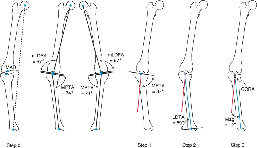
| mLDFA | Mechanical Lateral Distal Femoral Angle | 87 degrees | 85 to 90 degrees |
| MPTA | Medial Proximal Tibial Angle | 87 degrees | 85 to 90 degrees |
| LDTA | Lateral Distal Tibial Angle | 89 degrees | 86 to 92 degrees |
| JLCA | Joint Line Convergence Angle | 0 degrees | 0 to 2 degrees |
| mLPFA | Mechanical Lateral Proximal Femoral Angle | 90 degrees | 85 to 95 degrees |
By drawing these normal angles originating from the joint lines on a calibrated standing radiograph, the surgeon can project the normal proximal and distal mechanical axes of the deformed bone. The intersection of these projected lines is the cornerstone of deformity planning.
Identifying the Center of Rotation of Angulation
When the proximal and distal mechanical or anatomic axis lines of a deformed bone are drawn on a radiograph, they will eventually intersect. This point of intersection is the Center of Rotation of Angulation.
The Center of Rotation of Angulation represents the true apex of the angular deformity. A bone may have a single unifocal deformity or multiple multifocal deformities. Identifying the precise location of this intersection is the most critical step in preoperative planning, as it dictates where the correction must hinge to avoid secondary translation.
The Transverse Bisector Line and Osteotomy Rules
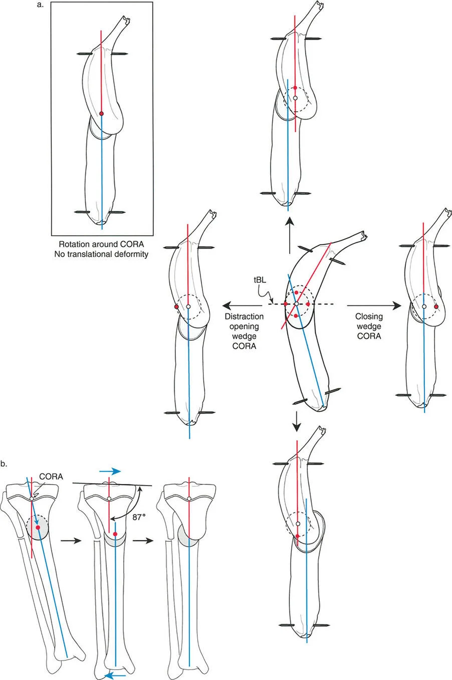
When the proximal and distal axes intersect to form the apex of the deformity, they create an angle. The line that perfectly bisects this angle is known as the transverse bisector line.
The rule of the transverse bisector line is the golden rule of deformity correction. If the Axis of Correction of Angulation lies anywhere on this bisector line, the deformity will correct without inducing a secondary translation. Dr. Paley codified this into three distinct osteotomy rules that dictate the relationship between the osteotomy cut, the hinge point, and the resulting bone alignment.
- Osteotomy Rule One When the osteotomy and the Axis of Correction of Angulation both pass through the Center of Rotation of Angulation, complete angular correction is achieved with the bone ends remaining completely apposed. No translation occurs.
- Osteotomy Rule Two When the osteotomy is made at a different level than the Center of Rotation of Angulation, but the Axis of Correction of Angulation remains on the transverse bisector line, the angulation is corrected, but the bone ends will translate relative to each other. This is mathematically necessary to realign the mechanical axis and is highly useful when the apex of deformity is near a joint where poor bone stock precludes safe fixation.
- Osteotomy Rule Three When the osteotomy and the Axis of Correction of Angulation are both placed away from the Center of Rotation of Angulation and off the transverse bisector line, an iatrogenic translation deformity is created. The mechanical axis will not be restored.
If the surgeon places the hinge point of the correction off the transverse bisector line, the bone segments will inevitably translate relative to one another, creating a new step off deformity that compromises intramedullary canal continuity and load bearing capability.
Biomechanics of Combined Angulation and Rotation Deformities
Visualizing a combined angulation and rotation deformity requires stepping out of two-dimensional radiographs and into dynamic three-dimensional space. When a bone is both angulated and rotated, it biomechanically resembles a twisted cylinder or a twisted banana.
The Fallacy of Staged Corrections and Transverse Cuts
If a surgeon attempts to correct the rotation by simply cutting the bone transversely and twisting the distal segment, a catastrophic biomechanical failure occurs. Because the bone is angulated, twisting the distal segment around the diaphyseal axis causes the distal mechanical axis to sweep through a cone in three-dimensional space.
For example, if you have a tibia with a 20 degree varus deformity and a 30 degree internal rotation deformity, performing a transverse osteotomy and externally rotating the distal segment by 30 degrees will inadvertently convert a portion of the varus deformity into an extension or flexion deformity. The angulation is not resolved; it is merely projected into a different anatomical plane. This phenomenon is why historical staged corrections required multiple complex wedge resections, leading to severe limb shortening.
Mathematical Coupling of Deformities
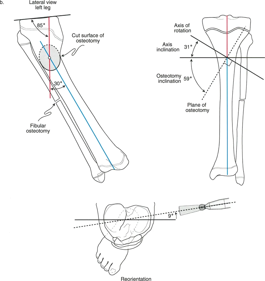
To solve this, the Paley principles utilize mathematical coupling. A combined angulation and rotation deformity can be viewed not as two separate problems, but as a single uniapical deformity existing in an oblique plane.
By calculating the true magnitude of the deformity and the true plane of the deformity, the surgeon can execute an inclined osteotomy. The osteotomy cut is angled relative to the orthogonal planes of the bone. When the bone is rotated along this inclined plane, the rotation mathematically forces the angulation to correct simultaneously. The steepness of the osteotomy cut is directly proportional to the ratio of angulation to rotation.
Preoperative Radiographic Templating Step by Step
Mastering simultaneous correction requires absolute precision in preoperative templating. The modern deformity surgeon must synthesize clinical examination findings with high quality radiographic data.
Clinical Assessment and Rotational Profiling
Radiographs alone cannot accurately quantify rotational deformities. The rotational profile must be determined clinically or via advanced cross-sectional imaging.
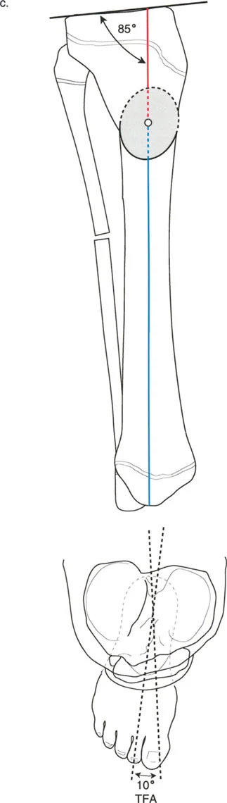
- Clinical Examination Assess the torsional profile of the lower extremity. For the femur, measure hip internal and external rotation in the prone position to determine femoral anteversion. For the tibia, measure the thigh foot angle and the transmalleolar axis.
- Computed Tomography Torsion Study The gold standard for quantifying rotation. CT slices are taken through the femoral neck, femoral condyles, proximal tibia, and distal tibia. The angles between these reference lines provide the exact degree of osseous torsion.
- Full Length Standing Radiographs Obtain a 51 inch weight bearing anteroposterior radiograph with the patellae oriented strictly forward. Obtain a corresponding full length lateral radiograph.
Executing the Multiplanar Analysis
Once imaging is secured, the surgeon executes a systematic drawing protocol to define the deformity parameters.
- Draw the Mechanical Axes Establish the mechanical axis of the proximal segment and the distal segment on both the anteroposterior and lateral radiographs.
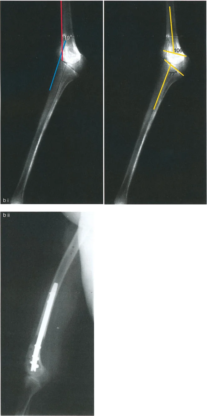
- Locate the AP and Lateral Apices Identify the Center of Rotation of Angulation on the AP view to determine coronal plane angulation. Identify the apex on the lateral view to determine sagittal plane angulation.
- Calculate the True Deformity Plane Using trigonometric formulas or specialized software, combine the coronal and sagittal angulations to find the oblique plane of maximum deformity.
- Integrate the Rotational Value Factor in the measured rotational deformity from the CT scan. This ratio of oblique plane angulation to axial plane rotation will dictate the exact inclination angle of the surgical cut.
Surgical Execution of the Inclined Osteotomy
Transitioning from the templating software to the operating room requires meticulous surgical technique. The inclined osteotomy is unforgiving; a deviation of even a few degrees in the saw cut can lead to residual malalignment.
Determining the Osteotomy Plane and Axis
The key to a successful simultaneous correction is establishing the correct axis of rotation during the surgery.
- Guide Wire Placement The surgeon inserts a guide wire that represents the calculated axis of correction. This wire must be placed exactly perpendicular to the true plane of the deformity, not simply perpendicular to the floor or the bone shaft.
- Fibular Management In tibial corrections, the fibula acts as a rigid strut that will prevent simultaneous angulation and rotation. A fibular osteotomy, typically in the middle or distal third, is mandatory. Resecting a small segment of the fibula ensures it does not tether the tibial correction.
- Executing the Bone Cut Using the guide wire as a reference, the osteotomy is performed. Depending on the planned fixation, this may be a single oblique saw cut, a dome osteotomy using a specialized drill guide, or a multiple drill hole and osteotome technique to preserve the endosteal blood supply.
- Applying the Correction Once the bone is completely mobilized, the distal segment is rotated along the inclined plane. As the rotation is manually applied, the surgeon will visually confirm that the angular deformity is simultaneously correcting.
Fixation Strategies for Complex Corrections
Once the bone is realigned, rigid fixation is required to hold the complex three-dimensional correction while bone healing occurs. The choice of fixation depends on the location of the osteotomy, soft tissue envelope, and surgeon experience.
- Hexapod Circular External Fixators Devices like the Taylor Spatial Frame are the ultimate evolution of the Paley principles. By applying a six axis external fixator, the surgeon can perform a simple transverse or oblique osteotomy and use computer software to gradually correct the angulation and rotation over several weeks. This method is highly forgiving, allows for postoperative adjustments, and protects the soft tissues from acute stretching.
- Intramedullary Nailing Acute simultaneous correction can be stabilized with a locked intramedullary nail. This requires advanced techniques such as the use of Poller screws or blocking screws. These screws are placed strategically in the concavity of the deformity to artificially narrow the medullary canal, forcing the nail to follow the corrected mechanical axis and preventing the bone from sliding back into a deformed position.
- Locking Plate Osteosynthesis For metaphyseal deformities near the joint line where intramedullary nailing is contraindicated, custom bent locking plates provide excellent stability. The surgeon must temporarily hold the correction with Kirschner wires or a bone clamp while the plate is applied to the tension band side of the bone.
Advanced Clinical Pearls and Pitfalls Avoidance
Mastering deformity correction is as much about avoiding complications as it is about mathematical precision. The following high yield pearls are critical for the advanced deformity surgeon.
- Respect the Soft Tissues Acute correction of severe rotation and angulation can stretch neurovascular structures. Always assess the common peroneal nerve during proximal tibial corrections. If a large valgus and internal rotation deformity is corrected acutely, prophylactic peroneal nerve decompression may be indicated to prevent foot drop.
- The Rule of the Concavity When planning the surgical approach and soft tissue releases, remember that the soft tissues on the concavity of the deformity are chronically contracted. Periosteal stripping and fascial releases should be concentrated on the concave side to allow the bone ends to open and realign without excessive tension.
- Beware the Sagittal Plane Surgeons often fixate on the coronal plane varus or valgus and forget the sagittal plane recurvatum or procurvatum. Always evaluate the lateral radiograph. An unrecognized sagittal deformity will alter the true plane of the deformity and render the inclined osteotomy calculations incorrect.
- Preserve the Periosteum The biological environment is just as important as the mechanical alignment. Use low speed drilling, cool the bone with saline irrigation, and avoid circumferential periosteal stripping. A mathematically perfect osteotomy will ultimately fail if the bone is rendered avascular and results in a nonunion.
- Verify with Intraoperative Fluoroscopy Never assume the preoperative plan translates perfectly to the table. Use the electrocautery cord or a specialized alignment grid over the fluoroscopy monitor to simulate the weight bearing line intraoperatively. Confirm that the mechanical axis passes exactly through the desired quadrant of the knee joint before final fixation is locked.
Conclusion and Future Directions in Deformity Correction
The correction of simultaneous angulation and rotation deformities represents the pinnacle of orthopedic biomechanics. By abandoning arbitrary wedge resections and embracing the mathematical elegance of Dr. Dror Paley’s principles, surgeons can achieve reproducible, anatomic restorations of the lower extremity.
Understanding the Center of Rotation of Angulation, mastering the transverse bisector line, and executing the inclined osteotomy are not merely academic exercises; they are essential skills for preserving joint longevity and restoring patient function. As technology advances, the integration of three-dimensional printed patient specific cutting guides, augmented reality intraoperative navigation, and robotic assisted osteotomies will further refine these principles. However, the foundational geometry established by the Paley method will remain the immutable core of complex deformity correction for generations of surgeons to come.
!!! info "Academic Resource & Medical Review"
This academic resource was prepared and medically reviewed by Prof. Dr. Mohammed Hutaif, Consultant Orthopedic & Spine Surgeon. It is formulated specifically for medical students, orthopedic residents, and surgeons preparing for high-stakes board examinations (AAOS, FRCS Tr & Orth, Arab Board).
!!! warning "Disclaimer"
The surgical techniques, classifications, and clinical guidelines presented herein are for educational and academic review purposes only. They are not intended to replace institutional protocols or independent clinical judgment.
You Might Also Like