Mastering Oblique Plane Deformities: Paley's Principles for Advanced Surgical Correction
Key Takeaway
Oblique plane deformities involve angular deviations in both coronal and sagittal planes, requiring 3D spatial analysis. Paley's principles guide precise understanding, mathematical calculation, and advanced surgical correction through osteotomies. This ensures accurate restoration of mechanical alignment and joint orientation, preventing residual malalignment.
Comprehensive Masterclass on Oblique Plane Deformities and Paley Principles
In the advanced realm of orthopedic surgery and limb reconstruction, deformities rarely manifest in a single orthogonal plane. Standard radiographic analysis relies heavily on strictly anteroposterior and lateral projections, yet the reality of human osteology and pathology is profoundly three dimensional. Deformities that project angular deviations on both the anteroposterior coronal plane and the lateral sagittal plane radiographs are defined as oblique plane deformities.
Understanding, analyzing, and surgically correcting oblique plane deformities represents one of the most intellectually demanding aspects of orthopedic deformity correction. It requires a fundamental cognitive shift from two dimensional radiographic interpretation to three dimensional spatial awareness. Utilizing the foundational principles established by Dr Dror Paley and the mathematical frameworks derived from the Ilizarov method, reconstructive surgeons can accurately calculate the true magnitude and orientation of a complex deformity, facilitating precise and reproducible surgical interventions.
This masterclass systematically deconstructs oblique plane deformities. It explores the underlying biomechanical principles, the mathematical derivations required for calculating true deformity magnitude, the meticulous radiographic planning process, and the advanced surgical execution of corrective osteotomies.
Core Principles of Paley Deformity Analysis
Before addressing the complexities of the oblique plane, the reconstructive surgeon must master the standard nomenclature and principles of deformity analysis as codified by Dr Dror Paley. The ultimate objective of any deformity correction is the precise restoration of normal mechanical alignment, physiological joint orientation, and equal limb length. Achieving these goals optimizes lower extremity biomechanics, normalizes load transmission across articular cartilage, and prevents premature joint degeneration.
Mechanical Axis Deviation and Alignment
The mechanical axis of the lower extremity is defined as a straight line drawn from the center of the femoral head to the center of the ankle joint at the tibial plafond. In a normally aligned lower limb, this mechanical axis line passes slightly medial to the center of the knee joint, typically traversing the medial tibial spine.
The deviation of this line from the physiological knee center is termed the Mechanical Axis Deviation. Quantifying the Mechanical Axis Deviation is the critical first step in determining whether a limb is in varus or valgus malalignment. A medial shift of the mechanical axis indicates a varus deformity, whereas a lateral shift indicates a valgus deformity. Correcting the Mechanical Axis Deviation is the primary biomechanical goal of lower limb realignment surgery.
Joint Orientation Angles and Normal Values
Joint orientation angles define the geometric relationship between the mechanical or anatomical axes of a long bone and its respective articular surfaces. Recognizing the normal physiological ranges of these angles is paramount, as the intersection of abnormal axes forms the basis of deformity planning.
Below is a summary of the critical joint orientation angles utilized in Paley deformity analysis.
| Parameter | Definition | Normal Range | Clinical Significance |
|---|---|---|---|
| mLDFA | Mechanical Lateral Distal Femoral Angle | 85 to 90 degrees | Evaluates distal femoral varus or valgus |
| MPTA | Medial Proximal Tibial Angle | 85 to 90 degrees | Evaluates proximal tibial varus or valgus |
| mLDTA | Mechanical Lateral Distal Tibial Angle | 86 to 92 degrees | Evaluates distal tibial varus or valgus |
| JLCA | Joint Line Convergence Angle | 0 to 2 degrees | Evaluates intraarticular ligamentous laxity |
| LPFA | Lateral Proximal Femoral Angle | 85 to 95 degrees | Evaluates proximal femoral varus or valgus |
| PDFA | Posterior Distal Femoral Angle | 79 to 87 degrees | Evaluates distal femoral flexion or extension |
| PPTA | Posterior Proximal Tibial Angle | 77 to 84 degrees | Evaluates proximal tibial recurvatum or procurvatum |
When a structural deformity is present, the proximal and distal mechanical axes of the affected bone intersect at an abnormal angle. Identifying this intersection point is the cornerstone of all subsequent preoperative planning.
Center of Rotation of Angulation and Angulation Correction Axis
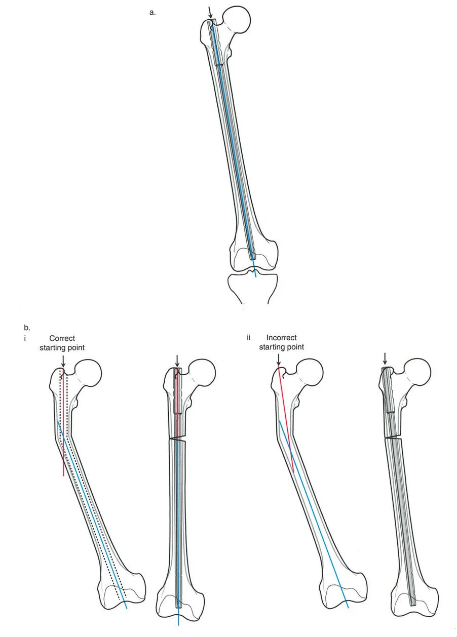
The Center of Rotation of Angulation is the intersection point of the proximal and distal mechanical or anatomical axes of a deformed bone. It represents the true apex of the deformity. Correcting a malaligned bone requires rotating the distal bone segment around a specific axis to perfectly align it with the proximal segment.
While the Center of Rotation of Angulation is a theoretical point on a two dimensional radiograph or a line in three dimensional space, the Angulation Correction Axis is the actual physical hinge point or axis around which the surgeon physically rotates the bone during the surgical correction. The spatial relationship between the Center of Rotation of Angulation and the Angulation Correction Axis dictates whether the bone will undergo pure angulation or a complex combination of angulation and translation.
The Four Parameters of Angular Deformity
To comprehensively characterize any angular deformity, especially those existing in an oblique plane, four distinct parameters must be strictly defined and quantified. Failure to accurately determine all four parameters will inevitably lead to residual malalignment following surgical correction.
Level of the Center of Rotation of Angulation
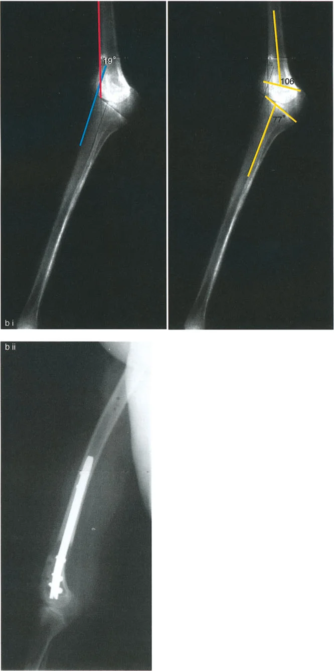
The level of the Center of Rotation of Angulation refers to the specific cross sectional level along the diaphysis or metaphysis where the apex of the deformity is anatomically located. Unlike other parameters, the level of the Center of Rotation of Angulation cannot be determined purely by mathematical calculation of the oblique plane. It must be visually identified by drawing and extending the intersecting proximal and distal axes on the orthogonal anteroposterior and lateral radiographs.
Orientation of the Deformity Plane
The orientation of the plane dictates the angle of the true plane of the deformity relative to the standard coronal or sagittal reference planes. In an oblique plane deformity, the bone is not simply bent anteriorly or medially. Instead, it is bent in a diagonal plane that exists somewhere between the pure coronal and pure sagittal planes. Determining this orientation is critical for hinge placement in external fixation or for orienting the osteotomy cut in internal fixation.
Apical Direction of the Deformity
The apical direction defines the spatial direction in which the apex of the deformity points. For example, a femur with a combined varus and apex anterior bowing deformity will have an apical direction pointing anterolaterally. Understanding the apical direction allows the surgeon to conceptualize the deformity in three dimensional space and plan the surgical approach and hardware placement accordingly.
True Magnitude of Angular Deviation
The magnitude is the true maximum angular deviation measured in degrees present within that specific oblique plane. The true magnitude is always greater than the apparent magnitude seen on either the isolated anteroposterior or isolated lateral radiograph. Correcting only the magnitude seen on the anteroposterior radiograph will leave the patient with a residual sagittal plane deformity.
Visualizing the Oblique Plane in Three Dimensions
When a long bone is deformed in an oblique plane, it casts a two dimensional projection on both the anteroposterior and lateral radiographs. A common and devastating pitfall for novice reconstructive surgeons is to treat the anteroposterior and lateral deformities as two separate mechanical problems requiring two separate surgical corrections. In reality, there is only one uniapical deformity, and it exists in a single oblique plane.
The True Plane and the Null Plane
To conceptualize the oblique plane, imagine rotating the patient under live fluoroscopy. As the C arm rotates around the deformed limb, there will be one specific angle of rotation where the deformity appears at its absolute maximum magnitude. This view represents the True Plane of the Deformity.
Conversely, if the C arm is rotated exactly ninety degrees away from the true plane, the radiograph will show a perfectly straight bone with zero angular deviation. This view represents the Null Plane.
To visualize this geometrically, imagine a three dimensional rectangular box. The anteroposterior radiograph is projected on the left wall, and the lateral radiograph is projected on the right wall. The true oblique plane is represented by a diagonal line traversing the floor of this box from corner to corner. The length of this diagonal line represents the true magnitude of the deformity, and its angle relative to the walls represents the orientation of the true plane.
Mathematical Calculation of Oblique Plane Deformities
Orthopedic surgeons utilize two primary mathematical methods to translate the apparent anteroposterior and lateral radiographic projections into the true oblique plane magnitude and orientation. These are the Graphic Method and the Trigonometric Method. Both methods require high quality, calibrated orthogonal radiographs to ensure accurate measurements.
The Graphic Method and Vector Analysis
The graphic method is a highly practical, visual approach to calculating oblique plane deformities. It utilizes the principles of a vector diagram and the Pythagorean theorem to approximate the true deformity.
To execute the graphic method, the surgeon draws a standard Cartesian coordinate system with an X axis and a Y axis.
1. The magnitude of the coronal plane deformity measured from the anteroposterior radiograph is plotted along the Y axis.
2. The magnitude of the sagittal plane deformity measured from the lateral radiograph is plotted along the X axis.
3. A rectangle is drawn using these two plotted points.
4. A diagonal line is drawn from the origin to the opposite corner of the rectangle.
The length of this diagonal line represents the true magnitude of the oblique plane deformity. The angle of this diagonal line relative to the X or Y axis represents the orientation of the oblique plane. While technically an approximation, the graphic method is highly reliable for clinical practice, particularly for deformities under thirty degrees.
The Trigonometric Method for Precise Magnitude
For profound deformities or when utilizing computer assisted hexapod frames, the trigonometric method provides absolute mathematical precision. Because angular deformities represent arcs rather than straight vectors, standard Pythagorean math slightly underestimates the true magnitude of severe deformities.
The exact trigonometric formulas for determining oblique plane parameters are as follows.
To find the true orientation angle of the oblique plane:
Tangent of Orientation Angle = Tangent of Coronal Deformity divided by Tangent of Sagittal Deformity
To find the true magnitude of the oblique plane deformity:
Tangent of True Magnitude = Square Root of the sum of the squared Tangent of Coronal Deformity and the squared Tangent of Sagittal Deformity
By utilizing these trigonometric formulas, the surgeon eliminates the minor approximation errors inherent in the graphic method, ensuring flawless data entry for advanced hexapod software systems.
Paleys Three Osteotomy Rules for Deformity Correction
Once the oblique plane deformity has been fully quantified, the surgeon must plan the physical correction. Dr Dror Paley defined three fundamental osteotomy rules that govern the relationship between the Center of Rotation of Angulation, the Angulation Correction Axis, and the osteotomy site. Mastering these rules is non negotiable for any deformity surgeon.
Osteotomy Rule One Pure Angulation
Rule One states that when the osteotomy passes directly through the Center of Rotation of Angulation, and the Angulation Correction Axis is placed exactly at the Center of Rotation of Angulation, the bone will undergo pure angulation.
Following the correction, the proximal and distal mechanical axes will perfectly collineate, and the bone ends at the osteotomy site will remain fully apposed with no translation. This is the most biomechanically stable and biologically favorable correction, as it maximizes bony contact for rapid osteogenesis.
Osteotomy Rule Two Angulation and Translation
Rule Two states that when the osteotomy is performed at a level separate from the Center of Rotation of Angulation, but the Angulation Correction Axis remains at the Center of Rotation of Angulation, the bone will undergo a combination of angulation and translation.
Following the correction, the proximal and distal mechanical axes will perfectly collineate. However, because the osteotomy was performed away from the hinge point, the bone ends at the osteotomy site will translate relative to one another. This rule is highly useful when the Center of Rotation of Angulation is located within a joint space or in an area of poor soft tissue coverage, necessitating a diaphyseal or metaphyseal osteotomy away from the deformity apex.
Osteotomy Rule Three Translation Outside the Axis
Rule Three states that when the osteotomy is performed outside the Center of Rotation of Angulation, and the Angulation Correction Axis is also placed outside the Center of Rotation of Angulation, the bone will undergo angulation, but the mechanical axes will not collineate.
This results in a secondary translation deformity. The proximal and distal axes will end up parallel but displaced. Rule Three is generally considered a planning error unless the surgeon is intentionally trying to create a translational offset to compensate for an adjacent deformity or to normalize a joint line convergence angle.
Step by Step Preoperative Radiographic Planning
Meticulous preoperative planning is the distinguishing factor between an average orthopedic surgeon and a master deformity correction specialist. Planning an oblique plane correction requires a systematic, step by step approach to ensure no parameter is overlooked.
Executing the Malalignment Test
The first step in any lower extremity deformity analysis is the Malalignment Test, performed on a full length, weight bearing, anteroposterior radiograph of both legs.
- Draw the mechanical axis of the entire lower extremity from the center of the femoral head to the center of the ankle joint.
- Measure the Mechanical Axis Deviation from the center of the knee joint.
- If the Mechanical Axis Deviation is abnormal, draw the individual mechanical axes of the femur and the tibia to isolate the source of the deformity.
- Measure the joint orientation angles including the mLDFA and the MPTA to determine if the deformity is femoral, tibial, or a combination of both.
- Evaluate the Joint Line Convergence Angle to rule out intraarticular ligamentous laxity contributing to the apparent malalignment.
Determining the Apex and Osteotomy Site
Once the specific bone causing the malalignment is identified, the surgeon must locate the apex of the deformity in both planes.
- Draw the proximal and distal mechanical or anatomical axes on the anteroposterior radiograph to find the coronal Center of Rotation of Angulation.
- Draw the proximal and distal axes on the lateral radiograph to find the sagittal Center of Rotation of Angulation.
- Correlate these two points to determine the true three dimensional level of the Center of Rotation of Angulation.
- Calculate the true magnitude and orientation of the oblique plane using either the graphic or trigonometric method.
- Select the optimal osteotomy site based on Paley Osteotomy Rules, considering local bone quality, soft tissue envelope, and required hardware placement.
Surgical Execution and Fixation Strategies
The surgical correction of an oblique plane deformity can be executed acutely utilizing internal fixation or gradually utilizing external fixation. The choice of fixation depends on the magnitude of the deformity, the presence of concurrent limb length discrepancy, and the condition of the surrounding soft tissue envelope.
Circular External Fixation and Hexapod Systems
For complex oblique plane deformities, particularly those associated with significant shortening or poor soft tissue, gradual correction with a circular external fixator is the gold standard. Modern hexapod systems, such as the Taylor Spatial Frame, utilize a Stewart platform configuration with six telescopic struts.
Hexapod systems provide six degrees of freedom, allowing for the simultaneous correction of angulation, translation, rotation, and length. The surgeon inputs the calculated deformity parameters, the frame mounting parameters, and the strut lengths into a specialized software program. The software generates a daily schedule for the patient to adjust the struts.
When treating an oblique plane deformity with a hexapod frame, the software mathematically resolves the anteroposterior and lateral inputs into the true oblique plane. However, the software is entirely dependent on the accuracy of the surgeon. If the surgeon inputs an incorrect Center of Rotation of Angulation or fails to account for rotational malalignment, the software will generate a flawed correction schedule, resulting in residual deformity.
Internal Fixation Techniques for Oblique Planes
Acute correction of oblique plane deformities can be achieved using closing wedge, opening wedge, or dome osteotomies, stabilized with locking plates or intramedullary nails.
When executing an acute correction, the osteotomy cut must be oriented perpendicular to the true oblique plane of the deformity, not simply perpendicular to the coronal or sagittal plane. If a closing wedge osteotomy is planned, the wedge must be resected from the convex side of the true oblique plane. If an opening wedge osteotomy is planned, the hinge must be left intact on the convex side of the true oblique plane, and the opening must occur on the concave side.
Acute corrections require meticulous soft tissue management. Correcting a severe oblique plane deformity acutely can stretch neurovascular structures, particularly the common peroneal nerve during valgus and procurvatum corrections. Prophylactic nerve decompressions may be indicated depending on the magnitude of the acute angular shift.
Advanced Clinical Pearls for the Orthopedic Surgeon
Mastering oblique plane deformities requires years of clinical experience. The following clinical pearls represent high yield insights for optimizing surgical outcomes and avoiding common reconstructive pitfalls.
- Beware of Rotational Deformities Masquerading as Angulation
A pure single plane deformity viewed on an improperly rotated radiograph will falsely appear as an oblique plane deformity. Always ensure the patella is perfectly forward facing for the anteroposterior radiograph and the femoral condyles are perfectly overlapped for the lateral radiograph. - The Rule of Halves for Hexapod Mounting
When applying a hexapod frame, strive to mount the reference ring perfectly orthogonal to the mechanical axis of the reference bone segment. If the ring is mounted obliquely, the software must compensate for the mounting error, increasing the complexity of the calculation and the risk of residual deformity. - Respect the Soft Tissue Envelope
In severe oblique plane deformities, the soft tissues on the concave side are chronically contracted. Gradual correction via distraction osteogenesis allows for histogenesis of the skin, muscle, fascia, and neurovascular structures, significantly reducing the risk of compartment syndrome or nerve palsy compared to acute correction. - Prioritize the Mechanical Axis
While restoring perfect anatomical alignment is the goal, the ultimate arbiter of a successful lower limb reconstruction is the restoration of the Mechanical Axis Deviation to a neutral position. A perfectly straight bone with a residual mechanical axis deviation will still lead to premature joint degeneration. - Utilize the Null Plane Intraoperatively
During acute corrections with internal fixation, rotate the C arm to the calculated Null Plane. If the correction is perfect, the bone should appear completely straight in this specific fluoroscopic view. If residual angulation is visible in the Null Plane, the correction is incomplete or the osteotomy was incorrectly oriented.
By rigorously applying Paley principles, mastering the mathematical calculations of the oblique plane, and adhering to strict preoperative planning protocols, the reconstructive orthopedic surgeon can reliably correct the most complex three dimensional limb deformities, restoring profound function and quality of life to the patient.
!!! info "Academic Resource & Medical Review"
This academic resource was prepared and medically reviewed by Prof. Dr. Mohammed Hutaif, Consultant Orthopedic & Spine Surgeon. It is formulated specifically for medical students, orthopedic residents, and surgeons preparing for high-stakes board examinations (AAOS, FRCS Tr & Orth, Arab Board).
!!! warning "Disclaimer"
The surgical techniques, classifications, and clinical guidelines presented herein are for educational and academic review purposes only. They are not intended to replace institutional protocols or independent clinical judgment.
You Might Also Like