Oblique Plane Deformities: Mastering 3D Orthopedic Correction with CORA
Key Takeaway
An oblique plane deformity is a single angular bone malalignment projecting on both frontal and sagittal radiographs. Correction involves 3D analysis using the Center of Rotation of Angulation (CORA) and Paley's osteotomy rules. This ensures precise realignment, restoring mechanical axis and preventing secondary translation.
Introduction to Oblique Plane Deformities
In the complex realm of orthopedic deformity correction, recognizing the true three dimensional nature of bone malalignment is paramount to achieving successful structural restoration. Historically, surgeons evaluated deformities in isolated two dimensional planes relying strictly on the coronal anteroposterior and the sagittal lateral radiographs. However, bones exist in a dynamic three dimensional space. What frequently appears as two separate deformities on standard orthogonal imaging such as a simultaneous varus and procurvatum is in reality a single angulation occurring in an oblique plane.
An oblique plane deformity is defined as any single level angular deformity that projects a magnitude of angulation on both the orthogonal frontal and sagittal radiographs. Understanding that these are not two distinct deformities but rather one unified deformity projected across two planes is the foundational concept of modern deformity correction pioneered by Dr Dror Paley. Failure to appreciate the true oblique plane leads to misguided surgical planning resulting in secondary translation, incomplete correction, altered joint biomechanics, or iatrogenic limb length discrepancies.
This comprehensive masterclass explores the biomechanics, graphical analysis, and surgical correction strategies for oblique plane deformities. By utilizing the principles of the Center of Rotation of Angulation and the Angulation Correction Axis, orthopedic surgeons can master the correction of complex lower extremity deformities with mathematical precision.
The Three Dimensional Nature of Bone Malalignment
To master deformity correction, the surgeon must abandon two dimensional thinking. When a bone bends at a single level in an oblique direction, the standard anteroposterior and lateral radiographs merely capture the shadows or projections of that bend. If a surgeon attempts to correct the coronal plane deformity and the sagittal plane deformity as two separate surgical steps or without understanding their vector relationship, the resultant mechanical axis will remain flawed. The oblique plane concept dictates that there is a single plane of maximal angulation. If the surgeon rotates their perspective or the fluoroscopic C arm to match this specific oblique angle, the entire deformity will be visible in a single view, and the orthogonal view 90 degrees to it will appear perfectly straight.
Defining the Oblique Plane Deformity
A true oblique plane deformity requires that the apex of angulation occurs at the exact same longitudinal level on both the anteroposterior and lateral radiographs. If the coronal apex is in the proximal diaphysis but the sagittal apex is in the distal diaphysis, this represents a multiapical deformity rather than a single oblique plane deformity. Identifying the exact horizontal level of the apex on both orthogonal views is the first and most critical step in confirming an oblique plane deformity.
Core Principles of Deformity Correction
Before delving into the mathematics and graphical plotting of oblique planes, the orthopedic surgeon must master the standard nomenclature and biomechanical principles of deformity correction established by Dr Dror Paley.
Mechanical Axis Deviation and Limb Alignment
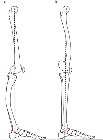
The mechanical axis of the lower extremity is defined by a line drawn from the center of the femoral head to the center of the ankle joint tibial plafond. In a normal, well aligned limb, this line passes precisely through the center of the knee joint. Mechanical Axis Deviation occurs when this weight bearing line falls medial or lateral to the center of the knee.
A medial Mechanical Axis Deviation indicates a varus alignment, leading to medial compartment overload and premature osteoarthritis. A lateral Mechanical Axis Deviation indicates a valgus alignment, overloading the lateral compartment. Correcting an oblique plane deformity aims to restore a neutral Mechanical Axis Deviation in the coronal plane while simultaneously normalizing the joint orientation angles in the sagittal plane. The magnitude of the Mechanical Axis Deviation dictates the required magnitude of correction, and any residual deviation postoperatively is considered a failure of the surgical plan.
Joint Orientation Angles in Deformity Analysis
Deformity analysis relies heavily on measuring the angles formed by the intersection of the mechanical or anatomic axes of the bone with the respective joint lines. Accurate measurement requires high quality, standing, long leg radiographs with the patella facing strictly forward to control for rotation.
Below is a comprehensive summary of the critical joint orientation angles utilized in the Paley method.
| Angle Acronym | Full Anatomical Name | Normal Value | Clinical Significance |
|---|---|---|---|
| mLDFA | Mechanical Lateral Distal Femoral Angle | 87 Degrees | Evaluates distal femoral coronal alignment |
| aLDFA | Anatomic Lateral Distal Femoral Angle | 81 Degrees | Used when mechanical axis is difficult to determine |
| MPTA | Mechanical Proximal Tibial Angle | 87 Degrees | Evaluates proximal tibial coronal alignment |
| mLDTA | Mechanical Lateral Distal Tibial Angle | 89 Degrees | Evaluates distal tibial coronal alignment |
| PPTA | Posterior Proximal Tibial Angle | 81 Degrees | Evaluates sagittal plane alignment of proximal tibia |
| ADTA | Anterior Distal Tibial Angle | 80 Degrees | Evaluates sagittal plane alignment of distal tibia |
| JLCA | Joint Line Convergence Angle | 0 to 2 Degrees | Evaluates intra-articular ligamentous laxity or wear |
The Center of Rotation of Angulation Method
The Center of Rotation of Angulation is the cornerstone of Paley deformity analysis. It is defined as the point at which the proximal and distal mechanical or anatomic axes of a deformed bone intersect.
To locate the Center of Rotation of Angulation, the surgeon must first draw the normal mechanical or anatomic axis of the proximal bone segment. Next, the normal axis of the distal bone segment is drawn. The point where these two lines cross is the Center of Rotation of Angulation.
In the context of an oblique plane deformity, the Center of Rotation of Angulation must be determined independently on both the anteroposterior and lateral radiographs. If the anteroposterior Center of Rotation of Angulation and the lateral Center of Rotation of Angulation correspond to the exact same longitudinal level of the bone, the surgeon is dealing with a true single oblique plane deformity.
Identifying Single Versus Multiple Centers of Rotation
Understanding the apical nature of the deformity dictates the surgical approach.
* Single Center of Rotation: Indicates a uniapical deformity. The axes intersect at a single point, meaning a single osteotomy can correct the entire deformity.
* Multiple Centers of Rotation: Indicate multiapical or complex bowing deformities. The proximal and distal axes do not intersect at a point that matches the bone deformity, or a mid diaphyseal line is required to connect them. This necessitates multiple osteotomies for complete anatomical restoration.
The Angulation Correction Axis
The Angulation Correction Axis is the theoretical hinge point around which the distal bone segment rotates to correct the deformity. In external fixation, this is the actual physical hinge. In internal fixation, it represents the theoretical pivot point of the bone segments. The relationship between the Angulation Correction Axis, the Center of Rotation of Angulation, and the osteotomy site forms the basis of the Paley Osteotomy Rules.
Paley Osteotomy Rules for Deformity Correction
Mastering oblique plane deformities requires strict adherence to the three Paley Osteotomy Rules. These rules dictate the biomechanical consequences of where the bone is cut relative to the Center of Rotation of Angulation and where the hinge or pivot point is placed.
Paley Osteotomy Rule One
When the osteotomy and the Angulation Correction Axis both pass through the Center of Rotation of Angulation, the bone segments will undergo pure angulation without any translation. The proximal and distal anatomical axes will become perfectly collinear.
This is the ideal scenario for most deformity corrections. In an oblique plane deformity, placing the osteotomy at the exact level of the apex and hinging the correction at that same level ensures that the bone straightens perfectly in three dimensional space. This is commonly achieved with a closing wedge, opening wedge, or neutral wedge osteotomy at the apex of the deformity.
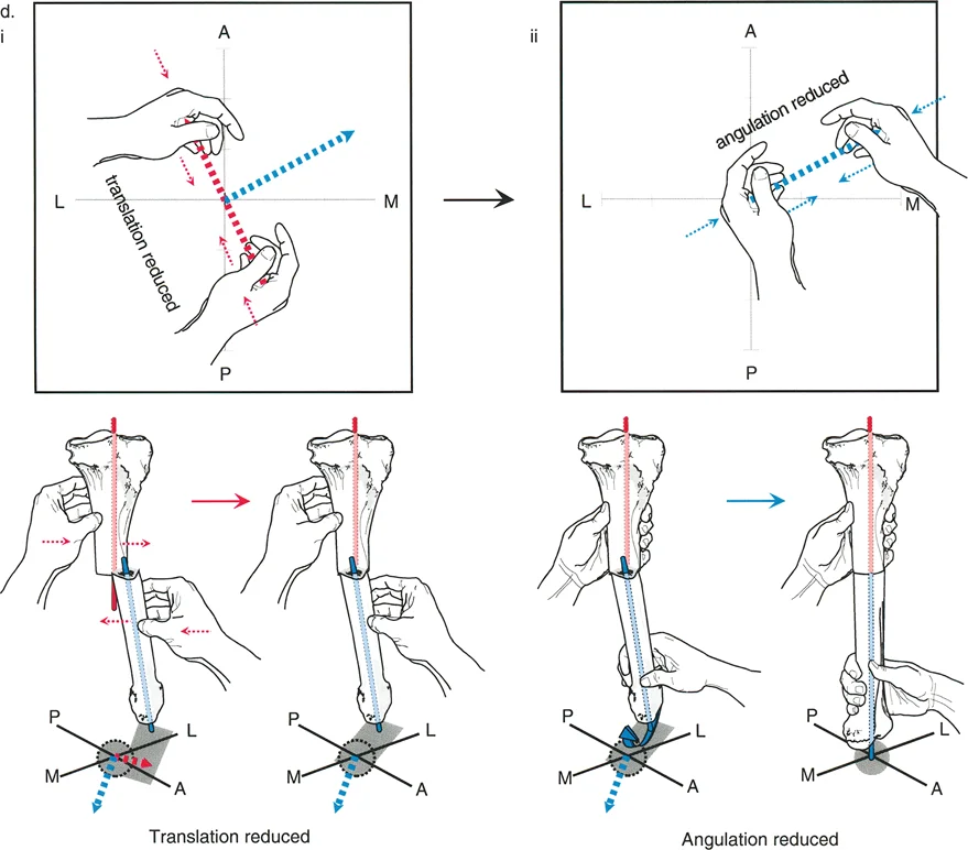
Paley Osteotomy Rule Two
When the Angulation Correction Axis passes through the Center of Rotation of Angulation, but the osteotomy is performed at a different level, the bone segments will undergo angulation combined with translation. Despite the translation at the osteotomy site, the proximal and distal anatomical axes will remain collinear, and the joint orientation angles will be restored.
This rule is highly useful in clinical practice. Often, the Center of Rotation of Angulation is located very close to a joint line, making an osteotomy at that exact level impossible due to lack of adequate bone stock for fixation. By placing the hinge at the Center of Rotation of Angulation but performing the osteotomy further down the diaphysis, the surgeon can achieve perfect alignment. The resulting translation at the osteotomy site is an expected and necessary biomechanical consequence to restore the mechanical axis.
Paley Osteotomy Rule Three
When the osteotomy and the Angulation Correction Axis are both placed at a level separate from the Center of Rotation of Angulation, the bone segments will undergo angulation, but the proximal and distal anatomical axes will end up parallel rather than collinear. This results in a translation deformity.
Generally, Rule Three is an unintended surgical error resulting from poor preoperative planning. However, it can be used intentionally in highly specific scenarios, such as correcting a mechanical axis deviation while simultaneously translating the bone to alter the joint load line, or when performing a periarticular osteotomy where joint line parallelism is prioritized over diaphyseal collinearity.
Graphical Analysis of Oblique Plane Deformities
To correct an oblique plane deformity effectively, the surgeon must calculate two critical variables. First is the true magnitude of angulation, which is the actual degree of the bend. This value will always be greater than the magnitude seen on either the anteroposterior or lateral radiograph alone. Second is the plane of angulation, which is the anatomical orientation of the true deformity relative to the standard coronal and sagittal planes.
The Mathematical Vector Approach
Because the anteroposterior and lateral radiographs are exactly 90 degrees orthogonal to each other, the true deformity can be calculated using precise vector mathematics and the Pythagorean theorem.
Let the anteroposterior magnitude of angulation be represented by the variable AP.
Let the lateral magnitude of angulation be represented by the variable LAT.
The true magnitude of the oblique plane deformity is calculated by squaring the AP magnitude, squaring the LAT magnitude, adding them together, and taking the square root of the sum.
The plane of the deformity is calculated using standard trigonometry, specifically the inverse tangent function, based on the ratio of the lateral and anteroposterior magnitudes.
For example, if a patient has a 15 degree varus deformity apex lateral and a 20 degree procurvatum deformity apex anterior, the true magnitude is the square root of 15 squared plus 20 squared, which equals exactly 25 degrees. The deformity is not 15 degrees, nor is it 20 degrees; it is a 25 degree bend occurring in an oblique anterolateral plane.
Step by Step Graphical Plotting Technique
While mathematical formulas are highly accurate, graphical plotting provides a highly intuitive visual representation that is invaluable for preoperative planning in the operating room. The graph is constructed by superimposing a transverse cross section of the bone at the level of the deformity apex.
- Setting the Axes for the Graph Draw a standard Cartesian coordinate graph. The horizontal X axis represents the coronal plane from Medial to Lateral. The vertical Y axis represents the sagittal plane from Anterior to Posterior.
- Plotting the Coronal Deformity Plot the magnitude of the anteroposterior deformity on the X axis. The direction of the vector must match the direction of the apex of the deformity. For example, a valgus deformity has a medial apex, so the vector is drawn from the origin toward the medial side of the X axis.
- Plotting the Sagittal Deformity Plot the magnitude of the lateral deformity on the Y axis. A recurvatum deformity has a posterior apex, so the vector is drawn from the origin toward the posterior side of the Y axis.
- Determining the Resultant Oblique Vector Draw a line from the origin to the coordinate point where the two plotted values intersect. The physical length of this resultant line represents the true magnitude of the oblique deformity. The angle this line makes with the axes represents the true anatomical plane of angulation.
Interpreting the Resultant Vector
The resultant vector provides the exact blueprint for surgical execution. If a surgeon is using a uniplanar device like a standard locking plate or an intramedullary nail, the resultant vector tells them exactly how much to rotate their implant or their fluoroscopy machine to view the deformity in its maximum profile.
If the vector lies at 53 degrees off the sagittal plane, the surgeon knows that rotating the leg or the C arm exactly 53 degrees will reveal the full 25 degree deformity, while the orthogonal view will show a perfectly straight bone. This is the secret to placing derotational blocking screws or orienting a single cut osteotomy.
Surgical Correction Strategies for Oblique Plane Deformities
Once the oblique plane deformity has been mathematically and graphically defined, the surgeon must select the appropriate fixation strategy. The choice depends on the magnitude of the deformity, the quality of the soft tissues, the presence of limb length discrepancy, and the patient profile.
Circular External Fixation and Hexapod Systems
Circular external fixators, particularly hexapod systems like the Taylor Spatial Frame, are the ultimate tools for managing oblique plane deformities. Because these systems utilize six degrees of freedom via six adjustable struts, they do not require the surgeon to physically build a hinge in the exact oblique plane.
Instead, the surgeon mounts the proximal and distal rings orthogonal to their respective bone segments. By inputting the anteroposterior deformity magnitude, the lateral deformity magnitude, and the exact mounting parameters into the software, the computer calculates the oblique plane resultant vector automatically. The software then generates a strut adjustment schedule that gradually corrects the oblique plane deformity simultaneously in all dimensions.
Key Takeaways for Hexapod Frames
* Allows for gradual soft tissue adaptation, reducing the risk of neurovascular compromise.
* Permits simultaneous correction of angulation, translation, rotation, and length.
* Postoperative residual deformities can be corrected via software adjustments without returning to the operating room.
Internal Lengthening Nails and Intramedullary Devices
Advancements in motorized internal lengthening nails have revolutionized deformity correction. While primarily designed for limb lengthening, these devices can be used to correct oblique plane deformities acutely at the time of surgery.
Correcting an oblique plane with an intramedullary nail requires meticulous technique. The surgeon must perform the osteotomy, acutely correct the bone in the calculated oblique plane, and pass the rigid nail to hold the correction. To prevent the nail from following the path of least resistance back into the deformed position, surgeons utilize Poller blocking screws.
By placing blocking screws in the concavity of the deformity in the exact oblique plane calculated during preoperative planning, the surgeon artificially narrows the medullary canal. This forces the intramedullary nail to pass in a trajectory that perfectly restores the mechanical axis.
Acute Correction Versus Gradual Correction
The decision to correct an oblique plane deformity acutely on the operating table versus gradually over weeks depends on several critical factors.
| Clinical Factor | Acute Correction Indication | Gradual Correction Indication |
|---|---|---|
| Deformity Magnitude | Small to moderate under 15 degrees | Large severe over 15 degrees |
| Soft Tissue Envelope | Healthy pliable skin | Poor skin compromised flaps |
| Neurovascular Risk | Low risk stretch | High risk peroneal nerve stretch |
| Limb Length | No significant discrepancy | Requires simultaneous lengthening |
| Fixation Method | Plates or Intramedullary Nails | Circular External Fixators |
Preoperative Planning Protocol
Success in the operating room is dictated entirely by the quality of the preoperative plan. Orthopedic surgeons must follow a rigid, reproducible protocol when approaching oblique plane deformities.
Formulating the Surgical Blueprint
- Obtain Standardized Imaging Acquire 51 inch standing anteroposterior and lateral radiographs. Ensure the patella is facing strictly forward to eliminate rotational artifact.
- Determine the Mechanical Axis Deviation Draw the mechanical axis line from the femoral head to the ankle center. Measure the deviation at the knee joint in millimeters.
- Measure Joint Orientation Angles Calculate the mechanical Lateral Distal Femoral Angle, Mechanical Proximal Tibial Angle, and corresponding sagittal angles to identify which bone segment is responsible for the deviation.
- Locate the Center of Rotation of Angulation Draw the normal proximal and distal axes on both the anteroposterior and lateral views. Confirm that the intersection points occur at the exact same horizontal level.
- Calculate the Oblique Plane Use the mathematical vector approach or graphical plotting technique to determine the true magnitude and the exact anatomical plane of the deformity.
- Select the Osteotomy Rule Determine if the osteotomy can be performed at the Center of Rotation of Angulation Rule One or if it must be performed at a different level Rule Two requiring calculated translation.
- Choose the Fixation Strategy Decide between acute correction with internal fixation or gradual correction with a hexapod external fixator based on the magnitude of deformity and patient specific factors.
Executing the Osteotomy
When performing the physical bone cut, the surgeon must respect the soft tissue envelope. For oblique plane deformities, a multiple drill hole and osteotome technique is preferred over a pure saw cut to minimize thermal necrosis and preserve the osteogenic potential of the periosteum. If using a hexapod frame, the osteotomy is typically completed after the frame is fully mounted and tensioned, ensuring that control of the bone segments is never lost.
Conclusion
Mastering oblique plane deformities is a defining milestone in the career of an orthopedic deformity surgeon. By transitioning from two dimensional radiographic observation to three dimensional vector analysis, the surgeon unlocks the ability to restore perfect anatomical alignment in even the most complex cases.
Strict adherence to the principles of Dr Dror Paley including the Center of Rotation of Angulation, precise measurement of Joint Orientation Angles, and the mathematical application of the Paley Osteotomy Rules ensures reproducible, outstanding clinical outcomes. Whether utilizing cutting edge hexapod external fixators or advanced intramedullary nailing techniques with blocking screws, the foundation of success remains rooted in meticulous graphical analysis and unwavering respect for the biomechanics of the human skeleton.
!!! info "Academic Resource & Medical Review"
This academic resource was prepared and medically reviewed by Prof. Dr. Mohammed Hutaif, Consultant Orthopedic & Spine Surgeon. It is formulated specifically for medical students, orthopedic residents, and surgeons preparing for high-stakes board examinations (AAOS, FRCS Tr & Orth, Arab Board).
!!! warning "Disclaimer"
The surgical techniques, classifications, and clinical guidelines presented herein are for educational and academic review purposes only. They are not intended to replace institutional protocols or independent clinical judgment.
You Might Also Like