Mastering Paley Osteotomy: Precision Frontal Plane Realignment & Deformity Correction
Key Takeaway
Paley Osteotomy Concepts provide a standardized, geometric method for analyzing and correcting complex limb deformities. They involve understanding mechanical axis deviation, joint orientation angles, the Center of Rotation of Angulation (CORA), and the Axis of Correction of Angulation (ACA) to achieve precise frontal plane realignment and restore normal limb biomechanics.
Introduction to Frontal Plane Realignment and Deformity Correction
For decades, orthopedic deformity correction was largely an observational science, a practice of estimating alignment intraoperatively and hoping for the best functional outcome. The paradigm shifted permanently with Dr. Dror Paley introduction of a standardized, geometric, and highly reproducible method for analyzing and correcting complex limb deformities. At the heart of this revolution are the Paley Osteotomy Concepts.
Understanding frontal plane realignment requires a fundamental shift from viewing bones as isolated biological cylinders to seeing them as mechanical levers defined by precise axes and angles. Whether you are performing a high tibial osteotomy for medial compartment osteoarthritis, correcting a post-traumatic distal femoral malunion, or applying a hexapod circular frame for a complex multi-apical deformity, mastering these principles is non-negotiable for the modern orthopedic surgeon.
This comprehensive guide deconstructs the foundational teachings of Dr. Paley, expanding on the biomechanics, geometric principles, and clinical applications of the Center of Rotation of Angulation, Bisector Lines, the Axis of Correction of Angulation, and the Three Osteotomy Rules. By internalizing these concepts, surgeons can execute deformity corrections with mathematical precision, ensuring optimal load distribution across articular surfaces and restoring normal limb biomechanics.
Understanding Mechanical Axis Deviation and Lower Limb Alignment
Before any surgical intervention can be planned, the surgeon must possess a rigid understanding of normal lower extremity alignment. Frontal plane realignment is primarily concerned with restoring the Mechanical Axis Deviation to neutral, thereby normalizing the weight-bearing forces transmitted through the hip, knee, and ankle joints.
Calculating the Mechanical Axis Deviation
The mechanical axis of the lower limb is a straight line drawn from the center of the femoral head to the center of the ankle joint (the center of the tibial plafond). In a normally aligned limb, this line passes just medial to the center of the knee joint, typically 8 to 10 millimeters medial to the midline of the tibial plateau.
When a structural deformity exists, this axis deviates. Mechanical Axis Deviation is defined as the perpendicular distance from the center of the knee joint to the mechanical axis line.
* Medial Mechanical Axis Deviation indicates a varus deformity, leading to pathological overloading of the medial compartment of the knee.
* Lateral Mechanical Axis Deviation indicates a valgus deformity, leading to pathological overloading of the lateral compartment and potential patellofemoral tracking issues.
Restoring the Mechanical Axis Deviation to its physiological location is the primary goal of frontal plane deformity correction, as failure to do so results in accelerated articular cartilage wear, ligamentous strain, and eventual joint destruction.
Joint Orientation Angles in the Frontal Plane
To determine exactly where the deformity originates (femur, tibia, or the knee joint itself), we must evaluate the joint orientation angles. These angles define the relationship between the mechanical or anatomical axes of the long bones and their respective joint lines. Dr. Paley standardized these measurements to allow for universal communication and precise surgical planning.
| Joint Orientation Angle | Abbreviation | Normal Range | Average Value | Clinical Significance |
|---|---|---|---|---|
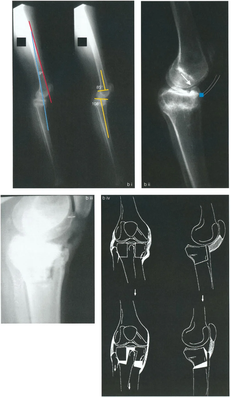
| Mechanical Lateral Distal Femoral Angle | mLDFA | 85 to 90 degrees | 88 degrees | Evaluates distal femoral varus or valgus deformity. |
| Medial Proximal Tibial Angle | MPTA | 85 to 90 degrees | 87 degrees | Evaluates proximal tibial varus or valgus deformity. |
| Joint Line Convergence Angle | JLCA | 0 to 2 degrees | 0 degrees | Evaluates intra-articular deformity or ligamentous laxity at the knee. |
| Lateral Distal Tibial Angle | LDTA | 86 to 92 degrees | 89 degrees | Evaluates distal tibial varus or valgus deformity at the ankle. |
When analyzing a full-length standing radiograph, a deviation in the mLDFA indicates a femoral deformity, while a deviation in the MPTA indicates a tibial deformity. If both are abnormal, the patient possesses a combined deformity requiring potentially complex, multi-level osteotomies.
The Center of Rotation of Angulation and Foundational Geometry
To correct a deformity, we must identify exactly where the angular deformity originates. This is done by drawing the proximal and distal mechanical or anatomical axes of the deformed bone segment. The intersection of these two lines brings us to the most critical concept in deformity correction.
Defining the CORA
The Center of Rotation of Angulation is the exact geometric point of intersection of the proximal and distal axes of the deformed bone.
When you draw the proximal and distal axis lines on a radiograph of an angular deformity, these lines intersect to form four angles centered perfectly on the Center of Rotation of Angulation. These four angles can be categorized anatomically based on their orientation:
* Proximal and Distal Angles These two angles are vertically opposed and are mathematically equal to each other. They represent the magnitude of the angular deformity.
* Medial and Lateral Angles These two angles are horizontally opposed and are also mathematically equal to each other.
To plan a precise correction, we must bisect these angles. The line that divides any of these angles into two mathematically equal halves is known as a bisector line.
The Transverse and Longitudinal Bisector Lines
Understanding the bisector lines is the key to executing an osteotomy that corrects angulation without inducing unwanted translation.
The Transverse Bisector Line
The transverse bisector line perfectly bisects the medial and lateral angles at the Center of Rotation of Angulation. This line is of paramount clinical importance because it represents the geometric plane along which the deformity can be corrected without inducing unwanted translation of the mechanical axis.
The Longitudinal Bisector Line
The longitudinal bisector line bisects the proximal and distal angles. By geometric definition, the transverse bisector line and the longitudinal bisector line are always exactly perpendicular (90 degrees) to each other.
The Axis of Correction of Angulation and Physical Hinge Placement
While the Center of Rotation of Angulation is a static geometric point on a two-dimensional radiograph, the Axis of Correction of Angulation is a dynamic, physical concept in the operating room. The Axis of Correction of Angulation is the actual mechanical hinge point around which the surgeon physically rotates the bone to correct the deformity.
In external fixation (such as an Ilizarov frame or Taylor Spatial Frame), the Axis of Correction of Angulation is the physical hinge connecting the proximal and distal rings. In internal fixation (such as a locking plate for an opening wedge osteotomy), the Axis of Correction of Angulation is the point on the intact opposite cortex (the cortical hinge) around which the bone opens or closes.
The entire foundation of Paley Osteotomy Concepts rests on the spatial relationship between the geometric Center of Rotation of Angulation and the physical Axis of Correction of Angulation.
Redefining CORA Through the Transverse Bisector Line
When the physical hinge passes exactly through the geometric Center of Rotation of Angulation, the proximal and distal axes of the bone rotate around the hinge. As correction occurs, the proximal mechanical axis and distal mechanical axis become perfectly collinear.
A critical geometric revelation in Paley principles is that collinear realignment of the proximal and distal axes occurs whenever the physical hinge is matched to ANY point on the transverse bisector line of an angular deformity.
Therefore, we can redefine the concept of a Center of Rotation of Angulation. A Center of Rotation of Angulation is any point that will lead to collinear realignment of the bone axes when the physical hinge passes through it. Consequently, all points on the transverse bisector line can be considered functional Centers of Rotation of Angulation. The specific point on the transverse bisector line that the surgeon chooses to place the physical hinge through is termed the ACA-CORA.
The Three Paley Osteotomy Rules for Deformity Correction
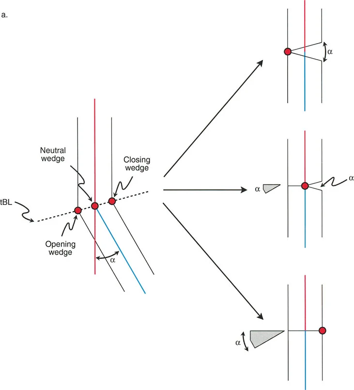
Dr. Paley codified the relationship between the osteotomy cut, the geometric Center of Rotation of Angulation, and the physical Axis of Correction of Angulation into three fundamental rules. Mastering these three rules allows the surgeon to predict exactly how the bone segments will behave in space during the correction.
Paley Osteotomy Rule One
The Rule The osteotomy cut and the Axis of Correction of Angulation both pass through the geometric Center of Rotation of Angulation.
The Biomechanical Result When the bone is cut at the Center of Rotation of Angulation and hinged at the Center of Rotation of Angulation, the proximal and distal bone axes will realign to become perfectly collinear without any translation of the bone ends.
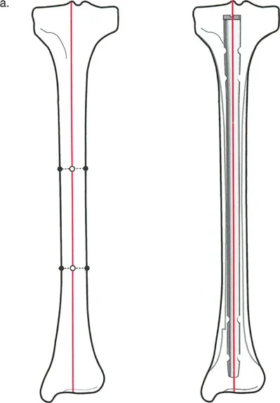
Clinical Application This is the ideal scenario for most diaphyseal deformities. The bone ends remain fully apposed (in a closing wedge) or open symmetrically (in an opening wedge) with no step-off. This creates optimal conditions for primary bone healing and straightforward internal fixation with intramedullary nails or plates.
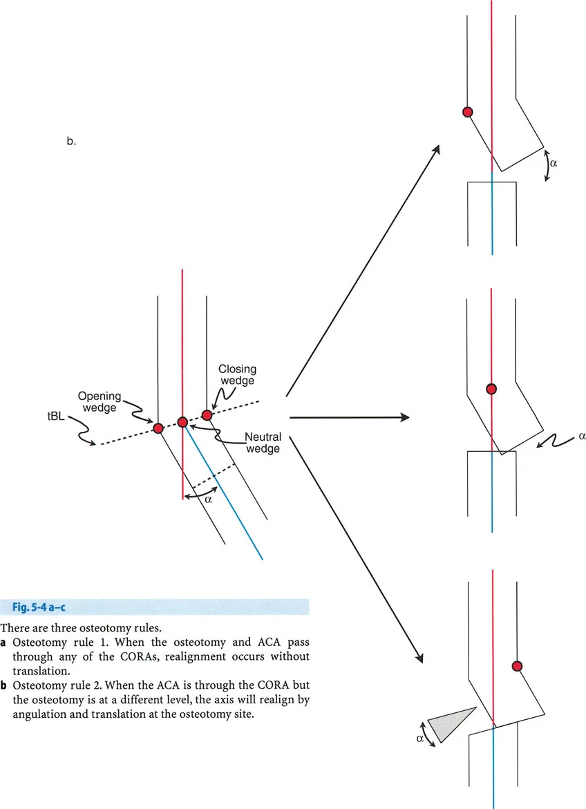
Paley Osteotomy Rule Two
The Rule The Axis of Correction of Angulation passes through the geometric Center of Rotation of Angulation, but the actual osteotomy cut is performed at a different level (proximal or distal to the Center of Rotation of Angulation).
The Biomechanical Result The proximal and distal mechanical axes will realign to become perfectly collinear. However, because the bone is cut away from the hinge point, the bone ends at the osteotomy site will translate relative to one another.
Clinical Application Rule Two is incredibly useful in juxta-articular deformities. Often, the geometric Center of Rotation of Angulation is located directly inside the joint line or very close to the articular surface, making an osteotomy at that exact level impossible without destroying the joint. By placing the hinge at the joint line (the Center of Rotation of Angulation) but making the cut further down the metaphysis or diaphysis, the surgeon achieves perfect axis realignment. The resulting translation at the osteotomy site is expected and accepted, though it may require specific plate contouring or translation of an intramedullary nail.
Paley Osteotomy Rule Three
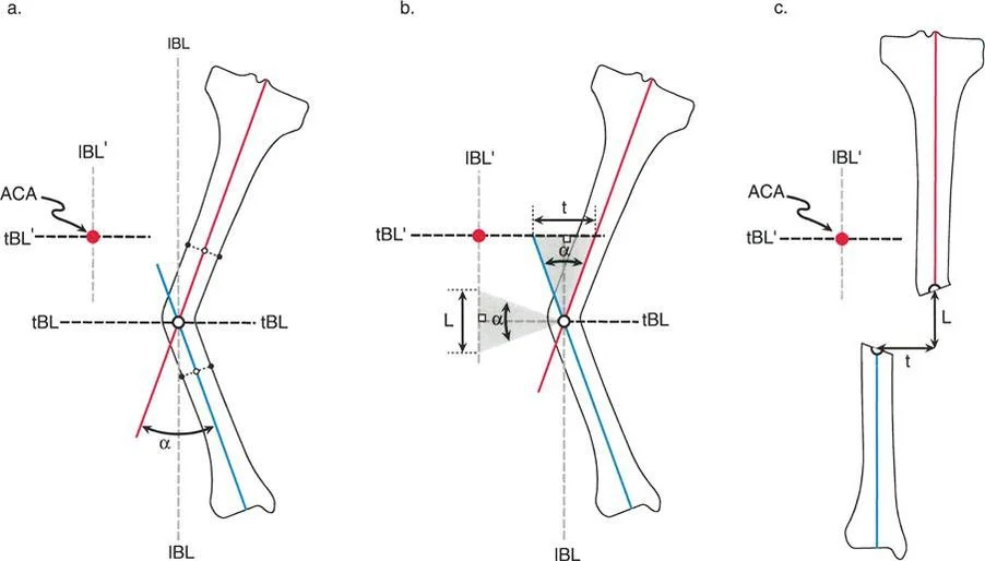
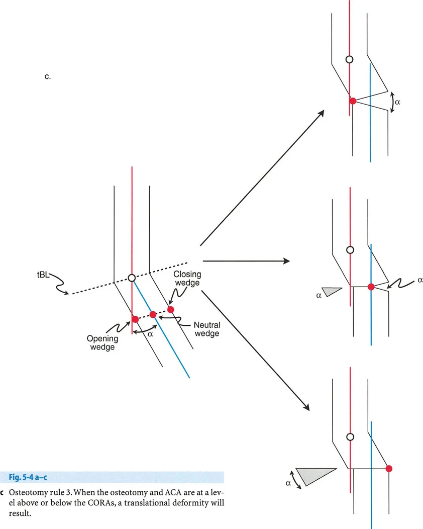
The Rule The osteotomy cut and the Axis of Correction of Angulation are both located at a level different from the geometric Center of Rotation of Angulation.
The Biomechanical Result The proximal and distal bone axes will become parallel to each other, but they will not be collinear. This induces a translation deformity (a step-off in the mechanical axis), often referred to as a Z-deformity.
Clinical Application Rule Three is generally considered an error in surgical planning if the goal was pure angular correction. If a surgeon inadvertently places the hinge away from the Center of Rotation of Angulation, they will induce a secondary translation that shifts the mechanical axis away from the center of the joint. However, Rule Three can be used intentionally to correct a pre-existing combined angular and translational deformity. By carefully calculating the distance of the hinge from the Center of Rotation of Angulation, the surgeon can simultaneously correct the angulation and translate the bone axis back to neutral.
Relationship of Osteotomy Type to Bisector Lines and Hinge Placement
The exact location of your physical hinge along the transverse bisector line dictates the type of osteotomy wedge you will create. This has profound implications for limb length, soft tissue tension, and bone healing biology.
Opening Wedge Osteotomy Mechanics
If the physical hinge is placed on the convex cortex of the osteotomy line, rotating the bone around this hinge will pull the concave cortex apart. This achieves an opening wedge correction.
- Biomechanics Opening wedge osteotomies lengthen the bone slightly. Because the hinge is on the convexity, the correction increases tension on the soft tissues on the concave side.
- Clinical Application The classic example is a medial opening wedge high tibial osteotomy for varus knees. The hinge is placed on the lateral cortex. Opening the medial side corrects the varus and tightens the medial collateral ligament.
- Surgical Considerations This technique requires bone graft or synthetic substitutes to fill the resulting void. It relies heavily on the stability of the lateral cortical hinge. If the lateral hinge fractures, the construct becomes highly unstable and requires rigid internal fixation.
Closing Wedge Osteotomy Mechanics
If the physical hinge is placed on the concave cortex of the osteotomy line, the surgeon must remove a wedge of bone from the convex side to allow the bone ends to meet. This achieves a closing wedge correction.
- Biomechanics Closing wedge osteotomies shorten the bone slightly. Because bone is removed and the gap is closed, it decreases tension on the soft tissues on the convex side.
- Clinical Application A common application is a lateral closing wedge distal femoral osteotomy for valgus knees. The hinge is placed on the medial cortex, and a wedge is removed laterally.
- Surgical Considerations Closing wedge osteotomies offer excellent bony apposition, leading to rapid primary bone healing without the need for bone grafting. However, the inherent shortening must be accounted for in preoperative planning, especially in patients with pre-existing limb length discrepancies.
Neutral Wedge and Dome Osteotomy Mechanics
If the physical hinge is placed precisely in the center of the bone (the central anatomical axis) along the transverse bisector line, the osteotomy will open on one side and close on the other.
- Biomechanics This is a neutral wedge osteotomy. It neither lengthens nor shortens the bone significantly. It maintains neutral soft tissue tension overall.
- Clinical Application This principle is utilized in dome osteotomies (cylindrical osteotomies). The bone is cut in an arc corresponding to the radius of the central hinge.
- Surgical Considerations Dome osteotomies allow for massive angular corrections without creating large bony voids or sacrificing limb length. They provide excellent bony contact area for healing but are technically demanding to execute, often requiring specialized crescentic saw blades or multiple drill holes.
Step by Step Preoperative Planning for Frontal Plane Deformity
Executing a flawless Paley osteotomy requires meticulous preoperative planning. The "eyeball" method is obsolete. Surgeons must employ the Malalignment Test to map the deformity geometrically.
Executing the Malalignment Test
- Obtain Proper Imaging Acquire a high-quality, full-length, weight-bearing anterior-posterior radiograph of both lower extremities. The patellae must be facing strictly forward to eliminate rotational artifact.
- Draw the Mechanical Axis Draw a line from the center of the femoral head to the center of the tibial plafond.
- Measure the Mechanical Axis Deviation Measure the perpendicular distance from the center of the knee joint to the mechanical axis line. Document whether the deviation is medial (varus) or lateral (valgus).
- Evaluate Joint Orientation Angles Measure the mLDFA, MPTA, and JLCA. Compare these to normal population values.
- If mLDFA is abnormal, the femur is deformed.
- If MPTA is abnormal, the tibia is deformed.
- If JLCA is > 2 degrees, consider intra-articular deformity or ligamentous laxity.
- Locate the Center of Rotation of Angulation Draw the proximal and distal mechanical axes of the deformed bone segment. Mark their intersection point as the Center of Rotation of Angulation.
- Draw the Bisector Lines Bisect the angle of deformity to establish the transverse bisector line. This line dictates where your physical hinge must be placed to avoid unwanted translation.
- Select the Osteotomy Rule and Type Decide whether an opening, closing, or dome osteotomy is most appropriate based on limb length and soft tissue constraints. Determine if the cut can be made at the Center of Rotation of Angulation (Rule One) or if it must be made away from the joint (Rule Two).
- Plan Fixation Choose the appropriate implant (locking plate, intramedullary nail, or external fixator) that will rigidly hold the planned correction while allowing for early mobilization.
Clinical Pearls for Surgical Execution and Fixation
Translating geometric planning from a digital screen to the physical operating room introduces variables that can compromise the correction. Adhering to these clinical pearls ensures the geometric plan is executed flawlessly.
- Protect the Cortical Hinge In opening or closing wedge osteotomies, the intact cortical hinge is your Axis of Correction of Angulation. If you fracture this hinge with an aggressive saw cut or forceful opening, you lose your geometric fulcrum, and the bone will translate unpredictably. Always leave 5 to 10 millimeters of intact cortex.
- Prophylactic Hinge Pinning To prevent inadvertent hinge fracture, place a smooth Kirschner wire precisely at your planned hinge point before making the saw cut. Cut directly up to the wire, but not through it. The wire acts as a physical stop for the saw blade and a stress riser that guides the bone to bend precisely around it.
- Account for the Saw Blade Thickness In a closing wedge osteotomy, the thickness of the saw blade (typically 1.2 to 1.5 millimeters) removes bone stock. Failing to account for this will result in over-correction. Always make your second cut slightly inside your planned line.
- Manage the Soft Tissues Bone deformity is always accompanied by soft tissue contracture. In a chronic varus deformity, the medial structures are contracted, and the lateral structures are stretched. Releasing the contracted tissues (e.g., fractional lengthening of the medial collateral ligament or iliotibial band release) is often necessary to achieve the planned bony correction without excessive force.
- Utilize Hexapod Technology for Complex Deformities For multi-apical deformities, deformities with poor skin envelopes, or cases requiring massive lengthening, internal fixation may be inadequate. The Taylor Spatial Frame utilizes Paley principles through a computer-assisted virtual hinge. By defining the Center of Rotation of Angulation in the software, the struts adjust gradually to achieve perfect Rule One or Rule Two corrections over time, respecting the limits of soft tissue stretch.
Conclusion to Mastering Paley Principles
The mastery of frontal plane realignment is the hallmark of an advanced orthopedic surgeon. Dr. Dror Paley geometric principles removed the guesswork from deformity correction, replacing it with mathematical certainty.
By systematically evaluating the Mechanical Axis Deviation, calculating joint orientation angles, defining the Center of Rotation of Angulation, and strictly adhering to the Three Osteotomy Rules, surgeons can tackle the most complex lower limb deformities with confidence. Whether utilizing a simple opening wedge plate or a complex circular external fixator, the underlying geometry remains the same. The bone is a lever, the osteotomy is a hinge, and precise preoperative planning is the blueprint for surgical success.
!!! info "Academic Resource & Medical Review"
This academic resource was prepared and medically reviewed by Prof. Dr. Mohammed Hutaif, Consultant Orthopedic & Spine Surgeon. It is formulated specifically for medical students, orthopedic residents, and surgeons preparing for high-stakes board examinations (AAOS, FRCS Tr & Orth, Arab Board).
!!! warning "Disclaimer"
The surgical techniques, classifications, and clinical guidelines presented herein are for educational and academic review purposes only. They are not intended to replace institutional protocols or independent clinical judgment.
You Might Also Like