Mastering Frontal Plane Deformity Correction: Mechanical & Anatomic Axis Planning

Key Takeaway
Frontal plane mechanical and anatomic axis planning is crucial for orthopedic surgeons. It quantifies lower extremity deformities, identifies the Center of Rotation of Angulation (CORA), and guides precise osteotomies. This systematic approach restores normal biomechanics, preventing joint degeneration and optimizing patient outcomes.
Frontal Plane Mechanical and Anatomic Axis Planning
Mastering frontal plane mechanical and anatomic axis planning is a fundamental requirement for any orthopedic surgeon, resident, or fellow engaging in complex deformity correction. Based on the pioneering principles established by Dr. Dror Paley, this systematic approach allows surgeons to accurately quantify deformities, identify the true apex of angulation, and execute precise osteotomies that restore normal lower extremity biomechanics.
When lower extremity alignment is compromised by congenital conditions, trauma, or metabolic bone disease, the resulting Mechanical Axis Deviation alters joint contact forces. This abnormal load distribution inevitably leads to premature articular cartilage degeneration, ligamentous strain, and significant functional impairment. By utilizing structured preoperative templating in the frontal plane, surgeons can reliably predict the exact location and magnitude of the necessary correction, thereby optimizing patient outcomes and ensuring the longevity of the native joints.
This comprehensive guide explores the intricacies of both mechanical and anatomic axis planning, detailing the step by step methodologies required to address diaphyseal, proximal metaphyseal, and multiapical femoral deformities.
Radiographic planning example demonstrating the initial assessment of lower extremity alignment.
Core Paley Concepts and Terminology
Before initiating any preoperative drawing, the surgeon must be fluent in the standardized terminology and normative values that define lower extremity alignment. Dr. Paley formalized these concepts to eliminate ambiguity in deformity analysis.
The Center of Rotation of Angulation represents the exact point where the proximal and distal bone axes intersect. Identifying the CORA is the most critical step in deformity planning, as it dictates the optimal level for the osteotomy. A deformity may possess a single CORA (uniapex) or multiple CORAs (multiapex), depending on the complexity of the osseous bowing.
Mechanical Axis Deviation quantifies the clinical severity of the malalignment. In a normal lower extremity, the mechanical axis line drawn from the center of the femoral head to the center of the ankle plafond should pass slightly medial to the center of the knee joint. When this line falls outside the normal central zone of the knee, Mechanical Axis Deviation is present, indicating a pathological load shift.
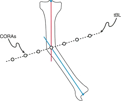
To accurately map these axes, surgeons rely on Joint Orientation Angles. These angles define the relationship between the mechanical or anatomic axis of a bone segment and its respective joint line.
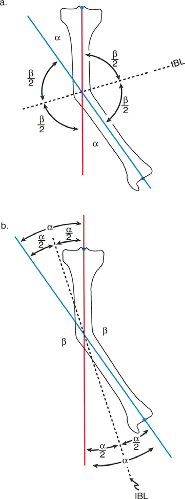
Illustration of joint orientation angles and mechanical axis lines in the frontal plane.
Standardized Joint Orientation Angles
Understanding the normal population averages for these angles is essential, especially when the contralateral limb is also deformed and cannot serve as a patient specific template.
| Angle Acronym | Full Definition | Normal Average | Normal Range |
|---|---|---|---|
| mLDFA | Mechanical Lateral Distal Femoral Angle | 87 degrees | 85 to 90 degrees |
| MPTA | Mechanical Proximal Tibial Angle | 87 degrees | 85 to 90 degrees |
| mLPFA | Mechanical Lateral Proximal Femoral Angle | 90 degrees | 85 to 95 degrees |
| aLDFA | Anatomic Lateral Distal Femoral Angle | 81 degrees | 79 to 83 degrees |
| aMPFA | Anatomic Medial Proximal Femoral Angle | 84 degrees | 80 to 89 degrees |
| JLCA | Joint Line Convergence Angle | 0 to 2 degrees | 0 to 2 degrees |
| AMA | Anatomic Mechanical Angle of the Femur | 7 degrees | 5 to 9 degrees |
Preoperative Radiographic Requirements
Accurate planning is entirely dependent on high quality imaging. The gold standard is a standing, weight bearing, full length lower extremity radiograph. The patient must be positioned with the patellae facing strictly forward, regardless of foot position. This "patella forward" orientation neutralizes rotational variations at the knee, ensuring that the frontal plane projection of the distal femur and proximal tibia is true and undistorted. Planning on supine or poorly rotated films will lead to catastrophic calculation errors and subsequent surgical failure.
Demonstration of proper radiographic alignment referencing the mechanical axis.
Step by Step Mechanical Axis Planning
Mechanical axis planning relies on drawing lines that connect the center points of the major joints. This method directly evaluates the load bearing axis of the limb and is highly effective for evaluating overall limb alignment and joint orientation.
Executing the Malalignment Test
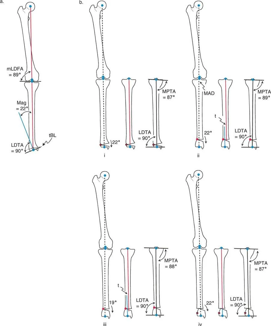
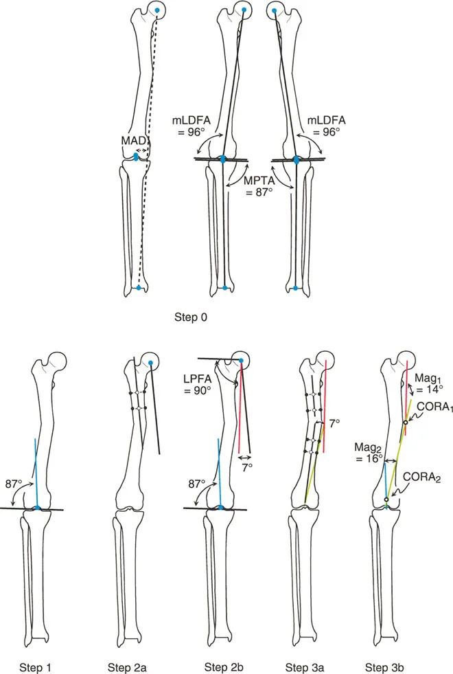
Step Zero of any deformity correction is the Malalignment Test. The surgeon draws a line from the center of the femoral head to the center of the ankle joint. If this line does not bisect the knee joint just medial to the tibial spines, Mechanical Axis Deviation is confirmed. The surgeon must then evaluate the mLDFA, MPTA, and JLCA to determine if the deviation originates from a femoral deformity, a tibial deformity, knee joint laxity, or a combination of these factors.
Establishing the Distal Mechanical Axis
Step One involves defining the Distal Mechanical Axis. If the distal femur is deformed, the surgeon must reconstruct where the normal mechanical axis should be. This is achieved by drawing a line starting from the center of the knee joint. If the contralateral femur is normal, the opposite mLDFA is used as a template. If the contralateral femur is also abnormal, the surgeon defaults to the population average mLDFA of 87 degrees. The line is drawn proximally at this 87 degree angle relative to the distal femoral joint line.
Defining the distal mechanical axis using standard joint orientation angles.
Establishing the Proximal Mechanical Axis
Step Two requires drawing the Proximal Mechanical Axis. This line originates at the center of the femoral head. For diaphyseal deformities, the Proximal Mechanical Axis is often drawn by referencing the mid diaphyseal line of the proximal segment and applying the Anatomic Mechanical Angle. Since the normal Anatomic Mechanical Angle is 7 degrees, the Proximal Mechanical Axis is drawn at a 7 degree offset from the proximal anatomic axis. If the deformity is very proximal, the surgeon may instead use the mLPFA (average 90 degrees) referenced from the proximal femoral joint line.
Locating the Center of Rotation of Angulation
Step Three is the identification of the CORA. The surgeon extends the Proximal Mechanical Axis distally and the Distal Mechanical Axis proximally. The exact point where these two lines intersect is the CORA. The angle formed by their intersection represents the true magnitude of the angular deformity. This intersection point dictates the optimal level for the corrective osteotomy to achieve complete realignment without introducing secondary translation.
Intersection of proximal and distal lines to identify the exact Center of Rotation of Angulation.
Step by Step Anatomic Axis Planning
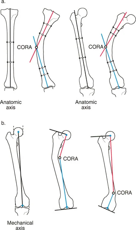
While mechanical axis planning is excellent for overall limb alignment, anatomic axis planning is frequently utilized for diaphyseal deformities and is vastly superior for analyzing multiapical deformities. Anatomic planning relies on the mid diaphyseal lines of the bone segments rather than the joint centers.
Drawing Mid Diaphyseal Lines
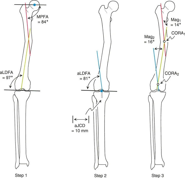
Step One in anatomic planning involves identifying the healthy, undeformed segments of the diaphysis. The surgeon identifies the center points of the medullary canal at two distinct levels within the proximal segment and connects them to form the proximal anatomic axis line. The same process is repeated for the distal segment to form the distal anatomic axis line.
Utilizing Joint Referenced Anatomic Lines
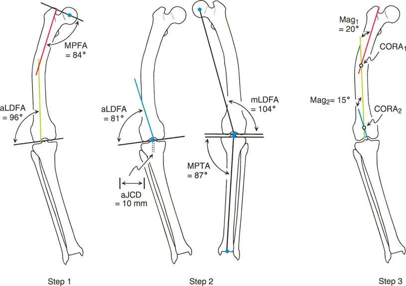
Step Two is necessary when the deformity extends into the metaphysis, leaving insufficient diaphysis to draw a reliable line. In these cases, the surgeon must draw a joint referenced anatomic axis. For the proximal femur, this line originates at the piriformis fossa and is drawn at the standard Anatomic Medial Proximal Femoral Angle of 84 degrees relative to the proximal joint line. For the distal femur, the anatomic axis originates at the anatomic Joint Center Distance, which is typically 10 millimeters medial to the center of the knee joint, and is drawn at the standard aLDFA of 81 degrees.
Anatomic axis planning utilizing mid diaphyseal lines and joint references.
Determining Anatomic Angulation
Step Three mirrors the mechanical method. The proximal and distal anatomic axis lines are extended until they intersect. This intersection is the anatomic CORA. In a pure diaphyseal deformity, the anatomic CORA and the mechanical CORA will be at the exact same level, and the magnitude of angulation will be identical.
Comparison of anatomic and mechanical axes intersecting at the deformity apex.
Diaphyseal Femoral Deformity Planning
Analyzing a standard diaphyseal deformity highlights the practical application of these principles. Consider a scenario where a patient presents with a midshaft femoral deformity and a concomitant contralateral femoral deformity.
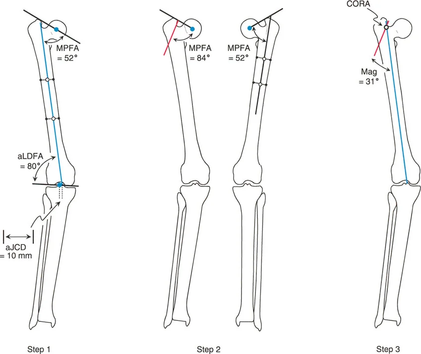
During mechanical axis planning, the Malalignment Test reveals significant Mechanical Axis Deviation due to the femoral bowing. Because the opposite femur cannot be used as a reliable template, the surgeon must rely on population averages. The Distal Mechanical Axis is drawn from the center of the knee at an average normal mLDFA of 87 degrees.
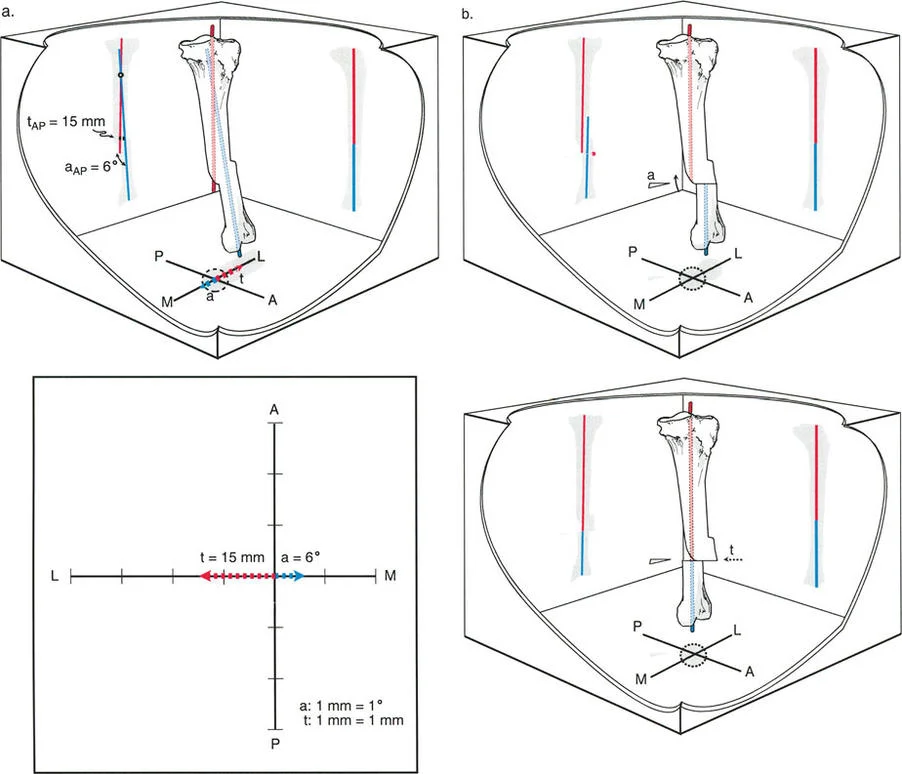
To establish the Proximal Mechanical Axis, the surgeon identifies the mid diaphyseal line of the proximal segment. Because the normal Anatomic Mechanical Angle is 7 degrees, the Proximal Mechanical Axis is drawn from the center of the femoral head at a 7 degree angle relative to this proximal mid diaphyseal line. The intersection of these two mechanical lines reveals the CORA in the diaphysis, and measures the magnitude of angulation, for example, at 15 degrees.
Preoperative templating of a diaphyseal femoral deformity using mechanical parameters.
When performing anatomic axis planning for the same diaphyseal deformity, the process is highly streamlined. The surgeon simply draws the mid diaphyseal line of the proximal segment and the mid diaphyseal line of the distal segment. Assuming the joint orientation angles (MPFA and aLDFA) are normal relative to these segments, no joint referenced lines are needed. The intersection of these two lines yields an identical CORA and a nearly identical magnitude of angulation, confirming the accuracy of the preoperative plan.
Anatomic axis planning for a diaphyseal deformity demonstrating streamlined intersection.
Proximal Metaphyseal Femoral Deformity Planning
Proximal deformities present a unique challenge because the short proximal segment often lacks sufficient length to accurately draw a mid diaphyseal line. This necessitates heavy reliance on joint orientation angles and contralateral templating.
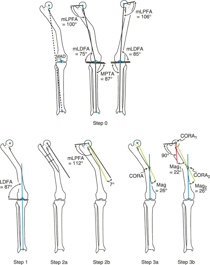
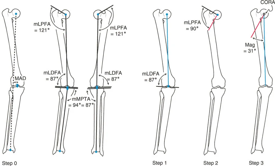
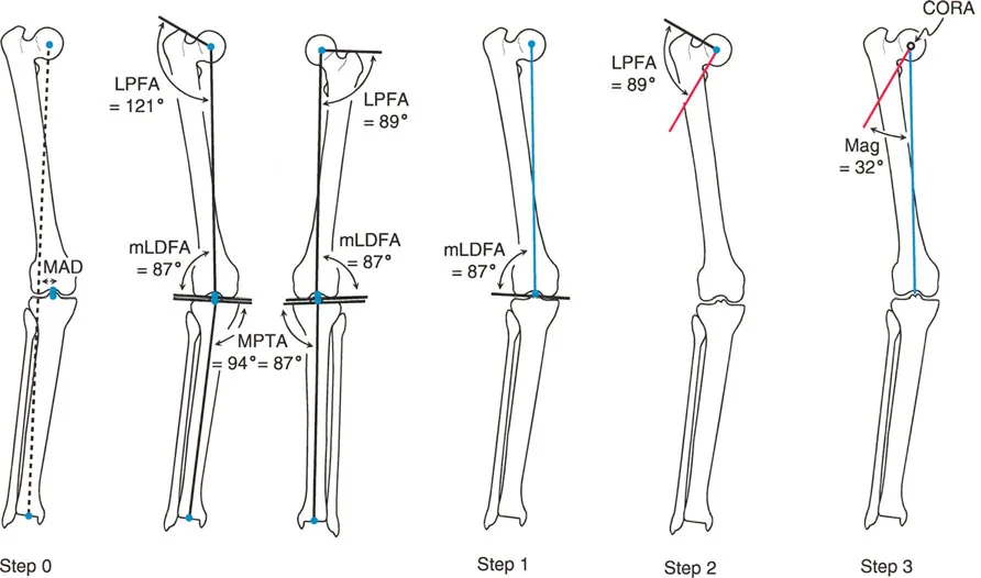
Consider a patient with a severe proximal metaphyseal deformity. The Malalignment Test shows Mechanical Axis Deviation. In mechanical planning, the Distal Mechanical Axis is drawn from the knee center. If the opposite mLDFA is normal, it can be used as a template angle; otherwise, the standard 87 degrees is used.
The complexity arises with the Proximal Mechanical Axis. Because the deformity is proximal, referencing the mid diaphyseal line is impossible. Instead, the surgeon evaluates the contralateral Mechanical Lateral Proximal Femoral Angle. If the contralateral mLPFA is normal (for instance, 89 degrees), this angle is used to draw the Proximal Mechanical Axis from the proximal joint line. The intersection of this line with the Distal Mechanical Axis places the CORA very proximally, often at or near the center of the femoral head, indicating a massive proximal deformity.
Addressing a proximal metaphyseal deformity where diaphyseal referencing is inadequate.
If the contralateral femur is also deformed, the surgeon is forced to use the average normal mLPFA of 90 degrees to establish the Proximal Mechanical Axis.
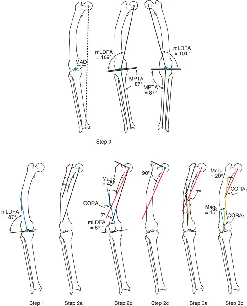
Anatomic planning for this same proximal deformity requires drawing a distal mid diaphyseal line. Because the proximal segment is too short, a joint referenced anatomic line must be drawn. The surgeon identifies the piriformis fossa and draws a line distally at the average normal Anatomic Medial Proximal Femoral Angle of 84 degrees (or uses the contralateral normal MPFA). The intersection of this joint referenced line with the distal mid diaphyseal line identifies the anatomic CORA and the magnitude of the hip deformity.
Utilizing the piriformis fossa and joint referenced angles for proximal anatomic planning.
Multiapical Femoral Deformity Planning
Multiapical deformities, where the bone exhibits two or more distinct apices of angulation, represent the pinnacle of deformity planning complexity. It is in these scenarios that the distinct advantages of anatomic axis planning become glaringly apparent.
Challenges with Mechanical Axis Planning
When attempting mechanical axis planning for a multiapical deformity, the surgeon will draw the Proximal Mechanical Axis from the femoral head and the Distal Mechanical Axis from the knee center. However, because there are multiple bends in the bone, these two lines will often be nearly parallel and may not even intersect within the boundaries of the femur.
To resolve this, the surgeon must construct a "middle mechanical axis line." This requires referencing the mid diaphyseal line of the central bone segment located between the two deformities. The middle mechanical axis is drawn at a 7 degree offset (the normal AMA) from this central diaphyseal line. The intersections of the Proximal Mechanical Axis with the middle mechanical axis, and the Distal Mechanical Axis with the middle mechanical axis, yield the two distinct CORAs. This process is mathematically sound but highly cumbersome and prone to drafting errors.
The complexity of mechanical axis planning in a multiapical deformity requiring a middle mechanical line.
The Superiority of Anatomic Axis Planning
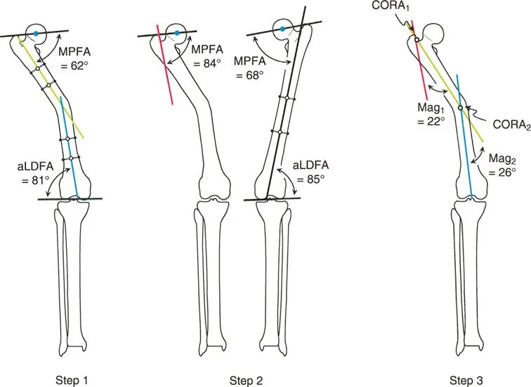
Anatomic axis planning is dramatically easier for multiapical deformities. The surgeon simply identifies the three distinct straight segments of the bone: the proximal segment, the middle segment, and the distal segment.
Mid diaphyseal lines are drawn through the proximal and middle segments. Their intersection immediately identifies the proximal CORA. Next, a mid diaphyseal line is drawn through the distal segment. If the distal segment is too short, a joint referenced anatomic line is drawn from the anatomic Joint Center Distance (10 millimeters medial to the knee center) at the standard aLDFA of 81 degrees. The intersection of this distal line with the middle diaphyseal line identifies the distal CORA.
By utilizing anatomic lines, the surgeon rapidly and accurately identifies both apices of deformity without the need to calculate offset mechanical middle lines.
Anatomic axis planning in a multiapical deformity, demonstrating clear and direct intersection points.
Paley Osteotomy Rules for Frontal Plane Correction
Identifying the CORA is only the first half of the battle. The surgeon must then decide where to perform the bone cut (the osteotomy) and how to realign the segments. Dr. Paley defined three fundamental osteotomy rules that govern how the bone will behave based on the relationship between the CORA, the osteotomy site, and the axis of hinge rotation.
Osteotomy Rule One
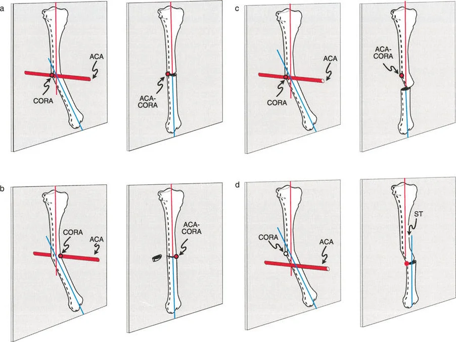
When the osteotomy is performed exactly at the level of the CORA, and the bone segments are rotated around a hinge placed exactly on the convex cortex of the CORA, pure angular correction is achieved. The proximal and distal bone axes will align perfectly without any secondary translation (displacement). This is the ideal scenario for restoring mechanical alignment and results in the most stable and biomechanically sound reconstruction.
Osteotomy Rule Two
Clinical realities often prevent the surgeon from cutting the bone exactly at the CORA. The CORA might be located within the joint space, in an area of poor soft tissue coverage, or in a region of compromised bone stock.
Under Rule Two, the osteotomy is performed at a different level than the CORA. However, the hinge of rotation is still placed on the convex cortex at the level of the CORA. When the correction is performed, the bone axes will align perfectly and remain parallel, but the bone ends at the osteotomy site will translate (shift) relative to one another. The surgeon must anticipate this translation and ensure that the chosen fixation method (such as an intramedullary nail or a spatial frame) can accommodate and stabilize this intentional displacement.
Application of Paley's Osteotomy Rules demonstrating angular correction and anticipated translation.
Osteotomy Rule Three
Rule Three describes what happens when the osteotomy is performed outside the CORA, and the hinge of rotation is also placed outside the CORA (typically at the osteotomy site itself). When the bone is angulated to correct the deformity, the proximal and distal bone axes will not align. Instead, a secondary translation deformity is created, resulting in a persistent zig zag mechanical axis.
Rule Three is generally considered a planning failure in pure frontal plane deformities, as it fails to restore the collinearity of the mechanical axis. However, it is occasionally used intentionally by advanced deformity surgeons to correct a preexisting translational deformity simultaneously with an angular deformity.
Clinical Pearls for Orthopedic Surgeons
To maximize success in the operating room, surgeons should internalize the following high yield clinical pearls regarding frontal plane planning:
- Validate the Contralateral Limb: Never blindly use the contralateral limb as a template without first verifying its joint orientation angles. Bilateral developmental deformities are highly common. When in doubt, default to the established population averages (mLDFA 87 degrees, MPTA 87 degrees).
- Account for the Anatomic Mechanical Angle: When transitioning between mechanical and anatomic planning in the femur, always remember the 7 degree AMA. Failing to account for this offset will result in a 7 degree malunion, which is sufficient to cause long term joint degeneration.
- Embrace Anatomic Planning for Complex Bowing: If a femur looks like a "snake" with multiple bends, abandon pure mechanical planning. Anatomic mid diaphyseal lines will save time, reduce drafting errors, and clearly highlight the multiple CORAs required for a double or triple osteotomy.
- Anticipate Translation with Rule Two: If you must cut away from the CORA, you must plan for translation. Ensure your implants are sized appropriately. A locking plate contoured for a normal bone will not fit a Rule Two correction without significant off axis bending or the use of blocking screws.
- The Patella is the Compass: A radiograph with a rotated patella is worse than no radiograph at all. It will artificially project a sagittal plane deformity into the frontal plane, leading to an entirely incorrect surgical plan. Demand strict "patella forward" positioning from the radiology department.
By rigorously applying these principles of mechanical and anatomic axis planning, the orthopedic surgeon transforms deformity correction from an art of estimation into a precise, reproducible science. Mastery of the CORA, joint orientation angles, and the osteotomy rules ensures that every surgical intervention predictably restores the patient's mechanical axis, preserving joint longevity and optimizing functional recovery.
!!! info "Academic Resource & Medical Review"
This academic resource was prepared and medically reviewed by Prof. Dr. Mohammed Hutaif, Consultant Orthopedic & Spine Surgeon. It is formulated specifically for medical students, orthopedic residents, and surgeons preparing for high-stakes board examinations (AAOS, FRCS Tr & Orth, Arab Board).
!!! warning "Disclaimer"
The surgical techniques, classifications, and clinical guidelines presented herein are for educational and academic review purposes only. They are not intended to replace institutional protocols or independent clinical judgment.
You Might Also Like