Mastering Frontal Plane Deformity Correction: The Paley Method
Key Takeaway
Frontal plane mechanical and anatomic axis planning, central to the Paley method, is a precise orthopedic technique. It involves using the Center of Rotation of Angulation (CORA) and specific joint orientation angles to accurately identify and correct limb deformities, restoring normal biomechanics and preventing complications like osteoarthritis and implant failure.
Introduction to Frontal Plane Deformity Planning
In the realm of modern orthopedic surgery, the transition from visually estimating or "eyeballing" a limb deformity to executing a mathematically precise, perfectly aligned osteotomy is what separates an average surgeon from a master deformity corrector. At the heart of this precision lies Frontal Plane Mechanical and Anatomic Axis Planning, a foundational pillar of Dr. Dror Paley's principles of deformity correction.
Historically, osteotomies were performed somewhat arbitrarily at the site of maximum bowing or the most accessible surgical approach. This antiquated approach frequently led to secondary iatrogenic translation deformities, joint malorientation, and altered biomechanics. The Paley method revolutionized orthopedic limb reconstruction by introducing the concept of the Center of Rotation of Angulation (CORA). By understanding how to manipulate mechanical and anatomic axes in the frontal plane, surgeons can accurately pinpoint the apex of a deformity, calculate its exact magnitude, and plan an osteotomy that restores normal joint biomechanics without inducing unwanted secondary translation.
This exhaustive masterclass transforms the core concepts of deformity planning into a high-yield, clinical deep-dive. Whether you are an orthopedic resident learning to draw your first axis lines on a digital PACS system, or an attending limb-lengthening specialist refining your preoperative templating for a complex multiapical malunion, this guide provides a comprehensive breakdown of uniapical versus multiapical angulation, the critical differences between mechanical and anatomic planning, and the strict osteotomy rules required for flawless surgical execution.
The Biomechanical Imperative of Lower Extremity Alignment
Before diving into the complex geometry of axis lines and preoperative templating, it is crucial to understand the biomechanical stakes of limb alignment. The lower extremity is essentially a complex, weight-bearing linkage system designed to efficiently transfer ground reaction forces. The mechanical axis of the lower limb, defined as a straight line drawn from the center of the femoral head to the center of the ankle joint, must pass precisely through the center of the knee joint (or slightly medial to it, depending on specific patient anatomy and constitutional varus).
When a frontal plane deformity exists, whether varus or valgus, this weight-bearing line deviates from its anatomic ideal. This deviation is formally quantified as Mechanical Axis Deviation (MAD).
Consequences of Uncorrected Mechanical Axis Deviation
Failing to recognize and correct MAD has profound, long-term consequences for the native joint and any future arthroplasty implants.
- Cartilage Overload and Early Osteoarthritis A shift of the mechanical axis by just a few millimeters exponentially increases the joint reactive forces on the affected compartment. A medial MAD (varus deformity) overloads the medial compartment of the knee, rapidly accelerating articular cartilage wear and leading to early-onset osteoarthritis.
- Ligamentous Strain and Joint Instability Chronic malalignment stretches the collateral ligaments on the convex side of the deformity. Over time, this leads to soft tissue attenuation and joint instability, which further exacerbates eccentric cartilage wear and creates a vicious cycle of joint destruction.
- Catastrophic Implant Failure In the context of Total Knee Arthroplasty (TKA), failing to recognize and correct extra-articular frontal plane deformities leads to eccentric loading of the prosthetic components. This results in accelerated polyethylene wear, aseptic loosening, and early catastrophic failure of the implant.
By utilizing rigorous frontal plane mechanical and anatomic axis planning, surgeons ensure that the mechanical axis is restored to the center of the knee, neutralizing abnormal vectors and preserving the longevity of the native joint or arthroplasty implants.
Core Principles of the Paley Method
Dr. Paley's approach to deformity correction is built upon a rigid, reproducible geometric framework. To master this framework, the orthopedic surgeon must become fluent in the language of limb alignment, specifically the CORA and the normal joint orientation angles.
Defining the Center of Rotation of Angulation
The Center of Rotation of Angulation (CORA) is the cornerstone of the Paley method. It is defined as the intersection point of the proximal and distal axis lines of a deformed bone.
When a bone is deformed in the frontal plane, it is essentially divided into two segments: a proximal segment and a distal segment. Each segment has its own mechanical and anatomic axis. If you draw the axis line for the proximal segment and extend it distally, and draw the axis line for the distal segment and extend it proximally, they will eventually intersect. This point of intersection is the CORA.
The angle formed by the intersection of these two lines represents the true magnitude of the angular deformity. Identifying the CORA is not merely an academic exercise; it dictates exactly where the osteotomy should be performed or how the hinge of an external fixator must be positioned to achieve pure angular correction without translation.
Joint Orientation Angles and Normal Values
To accurately draw proximal and distal axis lines, you must know what "normal" looks like. The Paley method relies on specific angular measurements that relate the mechanical and anatomic axes of the diaphysis to the articular surfaces of the adjacent joints.
Below is a high-yield summary table of the critical frontal plane joint orientation angles. Memorizing these values is non-negotiable for accurate preoperative planning.
| Angle Acronym | Full Name | Normal Value Range | Average Value |
|---|---|---|---|
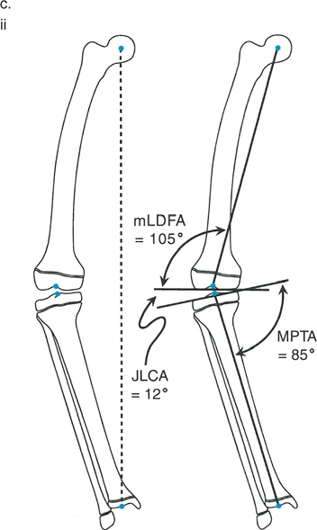
| mLDFA | Mechanical Lateral Distal Femoral Angle | 85 to 90 degrees | 88 degrees |
| aLDFA | Anatomic Lateral Distal Femoral Angle | 79 to 83 degrees | 81 degrees |
| MPTA | Medial Proximal Tibial Angle | 85 to 90 degrees | 87 degrees |
| LDTA | Lateral Distal Tibial Angle | 86 to 92 degrees | 89 degrees |
| LPFA | Lateral Proximal Femoral Angle | 85 to 95 degrees | 90 degrees |
| JLCA | Joint Line Convergence Angle | 0 to 2 degrees | 0 to 1 degree |
Surgical Pearl The JLCA is critical. A JLCA greater than 2 degrees indicates intra-articular pathology, such as asymmetric cartilage loss (e.g., medial compartment narrowing in varus knees) or ligamentous laxity. You must account for the JLCA when calculating your total correction, as correcting the bony deformity alone will not fully resolve the MAD if a severe soft-tissue or intra-articular deformity coexists.
Step by Step Guide to Frontal Plane Planning
In the Paley method, deformity planning follows a strict, sequential algorithm. Skipping steps or combining them leads to geometric errors and surgical failure.
Step Zero Assessing Mechanical Axis Deviation
Before analyzing individual bones, you must assess the entire limb using a 51-inch standing long-leg radiograph with the patellae oriented strictly forward.
- Draw a line from the center of the femoral head to the center of the tibial plafond (the Mechanical Axis Line).
- Assess where this line passes through the knee joint.
- Normally, it should pass 8mm to 10mm medial to the center of the knee joint.
- If the line passes medial to the medial compartment, the patient has a varus MAD. If it passes lateral to the lateral compartment, the patient has a valgus MAD.
This is known as the Malalignment Test. If MAD is present, you must proceed to the Malorientation Test to determine whether the deformity originates in the femur, the tibia, or the knee joint itself (JLCA).
Step One Drawing Distal Axis Lines
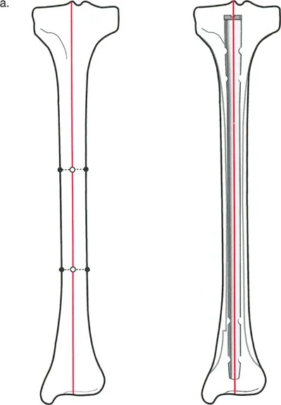
Once you have identified which bone is deformed (e.g., the tibia), you begin by drawing the axis of the distal segment.
Using the ankle joint line as your reference, draw a line proximally at an angle of 89 degrees (the normal LDTA). This establishes the normal mechanical/anatomic axis of the distal tibial segment.
Step Two Drawing Proximal Axis Lines
Next, use the proximal joint line as your reference. For the tibia, use the knee joint line and draw a line distally at an angle of 87 degrees (the normal MPTA). This establishes the normal mechanical/anatomic axis of the proximal tibial segment.
Step Three Deciding Between Uniapical and Multiapical Angulation
Step 3 is where the geometry truly comes to life. You have drawn your proximal and distal axis lines based on normal joint orientation angles. Now, you must decide whether the deformity is uniapical or multiapical, mark the CORA, and measure the magnitude of angulation.
Uniapical Versus Multiapical Deformities
The complexity of a bone deformity dictates how many axis lines you must draw to accurately represent the diaphyseal bone segments.
The Rule of Intersecting Lines
The rule of intersecting lines is a fundamental concept in deformity planning. It states that the number of CORAs is directly proportional to the number of axis lines required to map the deformed bone.
- Uniapical Deformity If the diaphyseal segments of the bone can be accurately represented by drawing only one proximal axis line and one distal axis line, they will intersect at a single point. Therefore, if there is only one pair of anatomic (or mechanical) axis lines drawn, there will be exactly one CORA and one magnitude of angulation. This represents a simple angular deformity.
- Multiapical Deformity In cases of severe bowing, developmental dysplasia (such as Osteogenesis Imperfecta), or complex post-traumatic malunions, a single proximal and distal line will not accurately capture the curvature of the bone. You must draw additional mid-diaphyseal lines to represent the intermediate bone segments. For each additional anatomic axis line drawn, there will be one additional CORA and magnitude.
Planning for Multiapical Deformity Correction
In the clinical scenario of a multiapical deformity, attempting to correct the entire curvature with a single osteotomy at a single CORA is a recipe for disaster.
If you attempt a single-level correction for a multiapical bow, the resulting geometry will force a massive translation of the bone segments. This translation can pull the bone entirely out of the soft tissue envelope, compromise vascularity, stretch neurovascular bundles, or create an unacceptable cosmetic zig-zag deformity that is impossible to plate or nail.
Recognizing multiapical deformities in Step 3 allows the surgeon to plan double or triple-level osteotomies. By identifying multiple CORAs, the surgeon can correct each specific apex of deformity by its respective magnitude. This restores the mechanical axis while keeping the bone neatly contained within its anatomic soft tissue envelope.
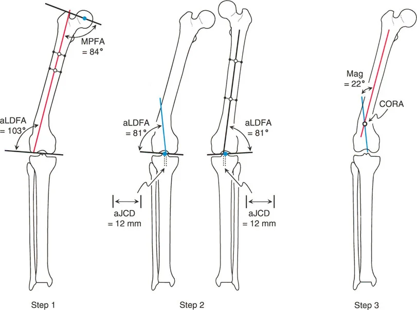
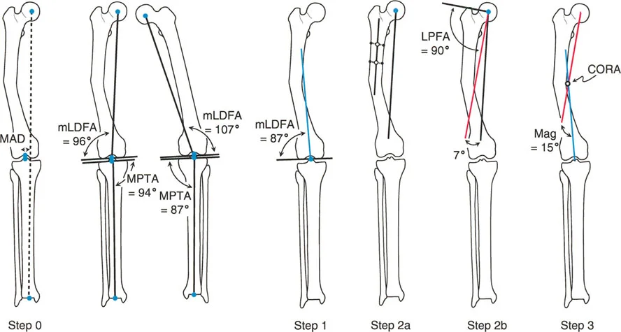
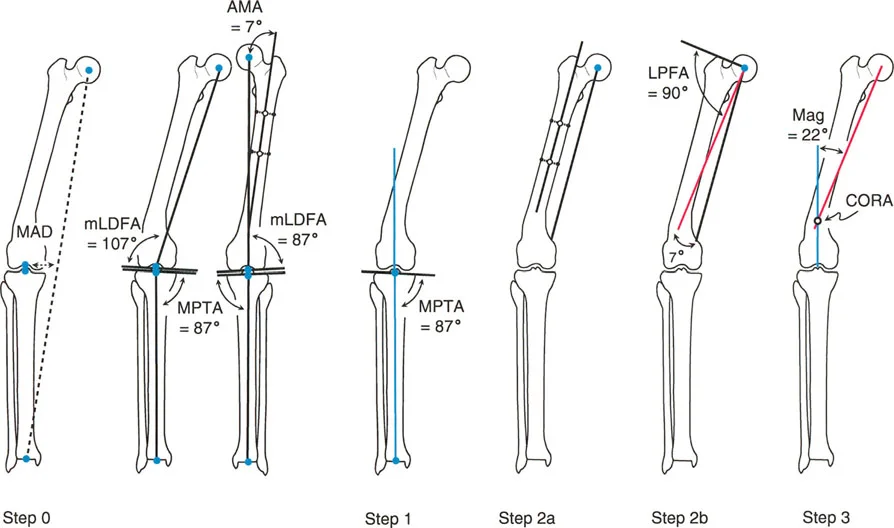
Mechanical Versus Anatomic Axis Planning in the Femur
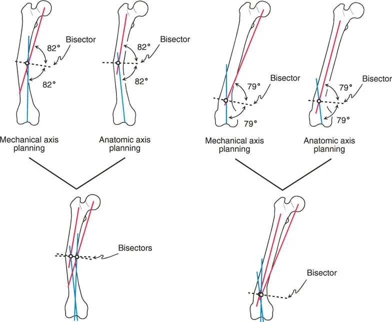
One of the most nuanced and frequently misunderstood concepts in frontal plane planning is the difference between mechanical and anatomic axis planning, particularly in the femur.
The tibia is relatively straightforward. Its anatomic axis (the line bisecting the medullary canal) and its mechanical axis (the line connecting the joint centers) are essentially parallel, usually exhibiting only 0 to 1 degree of difference. Therefore, planning a tibial deformity using anatomic lines yields the exact same CORA as planning with mechanical lines.
The femur, however, is a completely different biomechanical beast.
The Anatomic Mechanical Angle
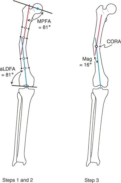
Due to the offset of the femoral neck and the medial projection of the femoral head, the anatomic axis of the femur and the mechanical axis of the femur diverge. This divergence is known as the Anatomic-Mechanical Angle (AMA).
In a normal adult, the AMA typically measures about 7 degrees (range 5 to 9 degrees). The mechanical axis runs from the center of the femoral head to the center of the knee. The anatomic axis runs straight down the center of the femoral diaphysis, exiting the knee slightly medial to the center.
Divergence of CORAs in Femoral Deformities
Because the mechanical and anatomic lines are not parallel, using them to plan a deformity will yield different intersection points and different CORAs.
When you plan a femoral deformity using the Anatomic Axis, the CORA will be located precisely on the anatomic axis line (usually within the medullary canal). When you plan the exact same deformity using the Mechanical Axis, the CORA will be located on the mechanical axis line, which often falls outside the physical bone entirely, especially in proximal or distal third deformities.
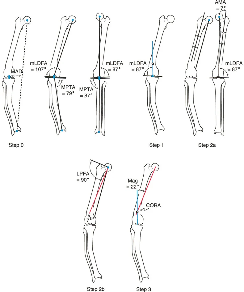
Surgical Pearl When should you use anatomic versus mechanical planning in the femur?
* Use Anatomic Axis Planning for diaphyseal deformities. It is much easier to template for intramedullary nails and diaphyseal plates when your axis lines follow the medullary canal.
* Use Mechanical Axis Planning for periarticular deformities (very proximal or very distal). Mechanical planning ensures that the joint orientation is perfectly restored relative to the weight-bearing line, which is critical for joint preservation and future arthroplasty.
The Three Osteotomy Rules of Paley
Identifying the CORA is only half the battle. The true mastery of the Paley method lies in executing the osteotomy. Dr. Paley established three strict geometric rules that dictate the relationship between the CORA, the osteotomy site, and the Axis of Correction of Angulation (ACA).
The ACA is the theoretical hinge point around which the bone segments rotate during correction. In external fixation (like a Taylor Spatial Frame or Ilizarov frame), the ACA is the physical hinge. In internal fixation, the ACA is the point around which you manually pivot the bone before applying a plate.
Osteotomy Rule One
Rule One states When the osteotomy passes through the CORA, and the ACA is placed on the CORA, pure angulation occurs without any translation.
This is the ideal scenario for deformity correction. By cutting the bone exactly at the apex of the deformity (the CORA) and pivoting the bone segments around that exact point, the mechanical axis is perfectly restored. The bone ends remain fully opposed, allowing for excellent bone-to-bone contact and rapid healing.
This rule can be executed clinically as an opening wedge osteotomy (where the ACA is on the convex cortex), a closing wedge osteotomy (where the ACA is on the concave cortex), or a dome osteotomy (where the ACA is in the center of the canal).
Osteotomy Rule Two
Rule Two states When the osteotomy is made outside the CORA, but the ACA remains on the CORA, the mechanical axis will be realigned, but the bone ends will translate.
There are many clinical scenarios where you cannot safely cut through the CORA. The CORA might be located inside the knee joint, in an area of poor soft tissue coverage, or in a zone of avascular sclerotic bone from a previous nonunion.
In these cases, you must perform the osteotomy at a different level (outside the CORA). However, to restore the mechanical axis, you must still hinge the correction around the original CORA. Because the cut is distant from the hinge point, the bone ends will translate (slide past each other) as they angulate. This translation is mathematically necessary to realign the joint axes. While it results in an offset medullary canal, the overall limb alignment is perfectly restored.
Osteotomy Rule Three
Rule Three states When the osteotomy is made outside the CORA, and the ACA is also placed outside the CORA, a secondary translation deformity is created.
This is the classic error made by surgeons who "eyeball" deformities. If you cut the bone away from the CORA and simply hinge the bone at the site of the cut, the joint orientation angles will remain parallel, but the mechanical axis will be severely translated. This creates a zig-zag deformity, known as iatrogenic translation. The limb may look straight to the naked eye, but the mechanical axis deviation (MAD) is worsened, leading to catastrophic joint overload.
Rule Three is almost always a surgical error to be avoided, though it is occasionally used intentionally in highly advanced corrections to address pre-existing translational deformities.
Clinical Application and Surgical Execution
Understanding the geometry is paramount, but translating these lines into surgical reality requires meticulous preoperative templating and the selection of appropriate fixation hardware.
Templating and Preoperative Workup
The foundation of any deformity correction is high-quality imaging.
1. Obtain weight-bearing, 51-inch long-leg radiographs.
2. Ensure the patellae are facing strictly forward to eliminate rotational artifact, which can falsely project as frontal plane angulation.
3. Utilize digital templating software (or traditional tracing paper) to draw the mechanical and anatomic axes.
4. Perform the Malalignment Test to quantify MAD.
5. Perform the Malorientation Test to identify the specific bone and joint contributing to the deformity.
6. Identify the CORA and measure the magnitude of the deformity.
7. Select your osteotomy level based on bone quality, soft tissue envelope, and Paley's Osteotomy Rules.
Choosing the Right Fixation Method
The choice of fixation depends heavily on the complexity of the deformity, the rules of osteotomy applied, and the patient's soft tissue status.
- Internal Fixation (Plates and Nails) Ideal for Rule One osteotomies (cut at the CORA). Opening wedge or closing wedge osteotomies can be acutely corrected and held rigidly with locking plates or intramedullary nails.
- Monolateral External Fixators Excellent for uniapical deformities requiring gradual correction or lengthening.
- Circular External Fixators (Ilizarov and Hexapod Frames) The gold standard for multiapical deformities, poor soft tissue envelopes, or cases requiring Osteotomy Rule Two. Hexapod frames (like the Taylor Spatial Frame) allow the surgeon to input the exact CORA and ACA into a software program, which calculates a precise daily strut adjustment schedule to gradually angulate and translate the bone ends safely.
Key Takeaways for the Orthopedic Surgeon
To master Frontal Plane Mechanical and Anatomic Axis Planning, keep these critical principles at the forefront of your surgical practice:
- Never Eyeball Alignment Always obtain proper long-leg standing films and systematically calculate the Mechanical Axis Deviation (MAD).
- Respect the Normal Angles Memorize the standard joint orientation angles (mLDFA 88 degrees, MPTA 87 degrees). Deviations from these norms dictate where your deformity lies.
- Identify the CORA Precisely The intersection of your proximal and distal axis lines is your CORA. This point dictates your entire surgical plan.
- Beware the Femoral AMA Remember that the anatomic and mechanical axes of the femur diverge by approximately 7 degrees. Ensure you are using the correct axis for your specific diaphyseal or periarticular plan.
- Follow the Osteotomy Rules If you cut at the CORA and hinge at the CORA (Rule 1), you get pure angulation. If you cut away from the CORA but hinge at the CORA (Rule 2), you get necessary translation. Never cut away from the CORA and hinge at the cut (Rule 3), as this causes iatrogenic axis deviation.
- Plan for Multiapical Complexity If a bone requires more than two axis lines to map its curvature, it is a multiapical deformity. Plan multi-level osteotomies to prevent massive, unacceptable bone translation.
By rigorously applying the Paley method, orthopedic surgeons can eliminate the guesswork from limb reconstruction, ensuring mathematically precise corrections that restore optimal biomechanics, preserve joint longevity, and dramatically improve patient outcomes.
!!! info "Academic Resource & Medical Review"
This academic resource was prepared and medically reviewed by Prof. Dr. Mohammed Hutaif, Consultant Orthopedic & Spine Surgeon. It is formulated specifically for medical students, orthopedic residents, and surgeons preparing for high-stakes board examinations (AAOS, FRCS Tr & Orth, Arab Board).
!!! warning "Disclaimer"
The surgical techniques, classifications, and clinical guidelines presented herein are for educational and academic review purposes only. They are not intended to replace institutional protocols or independent clinical judgment.
You Might Also Like