Surgery of the Hip
Primary total hip arthroplasty 239
Revision total hip arthroplasty 255
Hip resurfacing 262
Hip arthrodesis 264
Excision hip arthroplasty 267
Femoroacetabular impingement
surgery 268
Hip arthroscopy 272
Hip arthrography 275
Viva questions 277
| Hip | Range of motion |
| --- | --- |
| External rotation | 60° |
| Internal rotation | 40° |
| Flexion | 125° |
| Extension | 0° |
| Adduction | 25° |
| Abduction | 45° |
Optimum position of arthrodesis
1. External rotation: 0°–10°
2. Flexion: 20°–25°
3. Adduction: 0°–5°
Primary total hip arthroplasty
Preoperative planning
Indications
Total hip arthroplasty (THA) is indicated in painful conditions of the hip that have failed conservative management. These are too numerous to list in this book but the most frequent underlying conditions are
1. Osteoarthritis
2. Inflammatory arthritis and other arthropathies
3. Avascular necrosis
4. Trauma
Contraindications
5. Infection (generalised or of the hip joint)
6. Absolute dysfunction of the abductor complex, including profound neurological disease
Young age is a relative contraindication, though in the highly symptomatic patient, total hip arthroplasty should be discussed with and performed by an appropriately experienced surgeon.
Consent and risks
1. Mortality: 0.3%
2. Nerve injury: 1%
3. Infection: 1%–2% in osteoarthritis, 5% in rheumatoid arthritis
4. Thromboembolism; deep vein thrombosis: 2%
5. Pulmonary embolism: 1%
6. Dislocation: 3%
7. Heterotopic ossification: 10% (though the majority are asymptomatic)
8. Limb length discrepancy: 15%
9. Loosening: Revision surgery is required for loosening in up to 10% at 15 years
10. Component failure: Stem fracture, locking mechanism failure in modular uncemented cups and other failures of components are rare, but recognized, complications
Operative planning
Recent radiographs of the pelvis and hip must be available. A templating software programme or physical templates should be routinely used to indicate the appropriate site for the femoral neck cut and provide a guide to implant placement and sizing. Availability of the implants must be checked by the surgeon.
Anaesthesia and positioning
Anaesthesia is usually general, regional or combined. An initial dose of antibiotic is given intravenously. The antibiotic of choice depends upon local policy, but a common choice is a second-generation cephalosporin or a combination of gentamicin and flucloxacillin. Tranexamic acid is often administered before the skin incision is made to reduce intra-operative bleeding and the need for postoperative transfusion.
Patient positioning will depend on the surgical approach chosen by the surgeon. In the United Kingdom, the lateral position is most commonly used and requires well-fixed supports abutting the lumbo-sacral spine posteriorly and the bony pelvis anteriorly (Figure 10.1). The pelvis should be vertically orientated to aid cup positioning; if it is not vertical, the operating table can be tilted to properly align the pelvis. Bony prominences must be carefully padded. The hip joint should be sufficiently mobile to allow safe dislocation and intraoperative stability assessment. The surgical field is
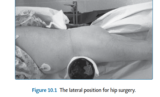
Figure 10.1 The lateral position for hip surgery.
prepared with a germicidal solution. Waterproof drapes are used with adhesive edges to provide a seal to the skin. The foot and lower leg are carefully excluded with a stockinette. If a lateral approach is to be used, a sterile ‘leg bag’ should be used to maintain sterility when the hip is displaced.
Surgical technique
The surgical approach may be dictated by the surgeon preference, previous surgical scars, patient body habitus, degree of bony deformity and implant selection. The two common approaches are the posterior and lateral approaches. A less commonly performed approach in the United Kingdom is the direct anterior approach to the hip (DAA) which is not described in this chapter.
Posterior approach (extensile)
Landmarks
The greater trochanter is palpated, particularly noting the tip and posterior border. The posterior superior iliac spine and femoral shaft are also useful palpable landmarks.
Incision A 15 cm skin incision is made with its midpoint lying over the posterior half of the greater trochanter (Figure 10.2). The proximal extent of the incision is curved posteriorly, to lie in the line of the fibres of the gluteus maximus. The distal portion lies along the line of the femoral shaft. Superficial dissection The incision is continued through subcutaneous fat and down to fascia lata. Beginning distally, the fascia lata is incised in line with the skin incision, overlying the lateral femur. Proximally this continues beyond the greater trochanter, in a posterior direction, to incise in line with the underlying fibres of the gluteus maximus. The fibres of the gluteus maximus are gently split, using diathermy to coagulate bleeding vessels. The fascial incision should run from about 6 cm above the tip of the greater trochanter down to the insertion of the gluteus maximus tendon on the posterior femur (Figure 10.3). 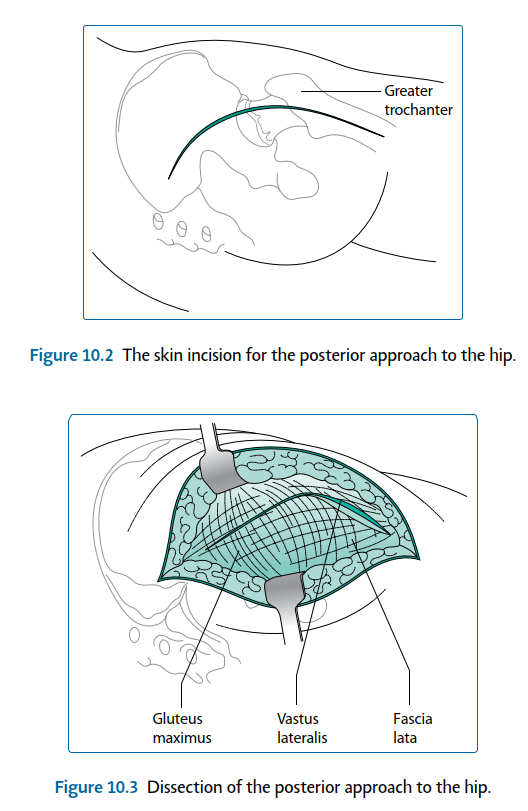
Figure 10.2 The skin incision for the posterior approach to the hip.
Gluteus maximus
Vastus lateralis
Fascia lata


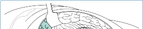
Figure 10.3 Dissection of the posterior approach to the hip.
A self-retaining retractor is carefully placed underneath the fascia to provide adequate exposure to further dissection.
Deep dissection
Structures at risk
1. Sciatic nerve : See later.
2. Inferior gluteal artery : Lying below piriformis. If it is cut, immediate supine repositioning of the patient and abdominal approach to tie off the internal iliac artery may be required to arrest the haemorrhage.
3. Obturator arterial branches : Present within quadratus femoris. The trochanteric bursa is now visible, covering the short external rotators and lying below the posterior border of gluteus medius (Figure 10.4). This can be swept off the short external rotators, using blunt or sharp dissection. Tendon of gluteus medius
Fascia lata
Short external rotators Greater trochanter
Vastus lateralis Quadratus femoris
Fascia lata
Gluteus maximus
Fat over short rotators


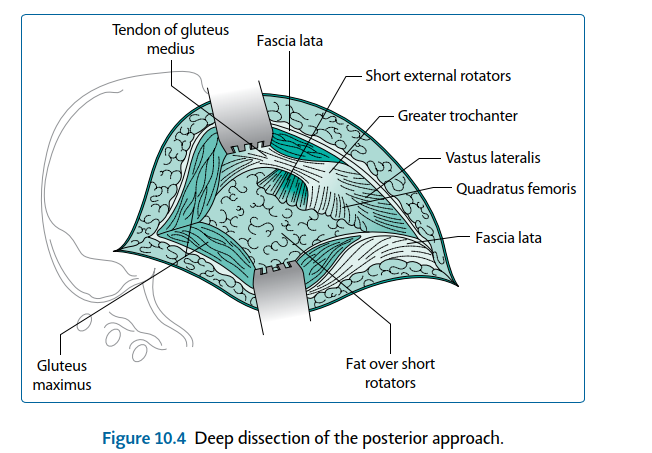
Figure 10.4 Deep dissection of the posterior approach. At this point the sciatic nerve can be palpated and/or visualised. Aggressive dissection around the nerve is not recommended, certainly in primary arthroplasty it is unnecessary and can increase the risk of damaging the epineurial vessels, causing a haematoma and potential neuropraxia. The sciatic nerve exits the sciatic notch and passes into the posterior thigh underneath the piriformis and overlying the following short external rotator muscles (listed from cranial to caudal) (Figure 10.5): 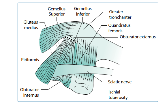
1. Gemellus superior
2. Obturator internus
3. Gemellus inferior
4. Obturator externus
5. Quadratus femoris
The nerve then runs down underneath the gluteus maximus’ tendon at its femoral insertion.
An assistant now internally rotates the extended hip and flexes, stretching the short external rotators, making them easier to divide. This also increases the distance between the sciatic nerve and the site of division of these short muscles. Strong, stay sutures are inserted into the tendons of obturator internus and piriformis, just below their insertion into the femur. Visible vessels within the operative field are coagulated: typically these lie on the tendon of piriformis and within the substance of quadratus femoris. The short external rotators, from piriformis down to gemellus inferior, are divided as close to their insertion onto the femur as possible. If further access is required, the division can be carried on further distally. The muscles are allowed to rest over the sciatic nerve, providing some protection for it throughout the rest of the operation. This exposes the posterior capsule of the hip joint. To improve visibility, the interval between the superior part of the hip capsule and the gluteus minimus is identified and dissected free with blunt dissection or scissors. This view is maintained by inserting a Hohmann retractor in the interval to displace the gluteus minimus superiorly. The capsule is incised transversely to gain access. The visible portion of capsule can either be excised or preserved for later repair. The visible portion of the acetabular labrum is excised.
Lateral approach
Landmarks
6. Central landmark is the greater trochanter.
7. The anterior superior iliac spine (ASIS) and the femoral shaft are also palpable and act as useful reference points.
Incision A straight 15 cm incision is created, parallel to the femoral shaft and centred on the anterior half of the greater trochanter (Figure 10.6). Superficial dissection The incision is continued through subcutaneous fat and down to fascia lata. The fascia lata is incised distally in line with the skin incision overlying the lateral femur and proximally in line with the fibres of gluteus maximus (Figure 10.7). At this point a self-retaining retractor is inserted. Deep dissection
Structures at risk
Superior gluteal nerve – between the gluteus medius and minimus; this may be as close as 3 cm above the tip of the greater trochanter.
Greater trochanter

Figure 10.6 The skin incision for the lateral approach to the hip.
Fascia lata
Tendon of gluteus medius


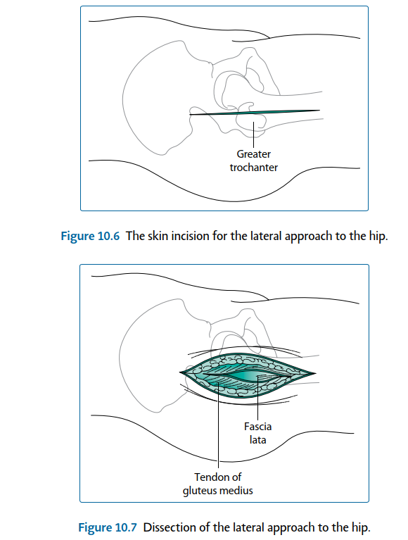
Figure 10.7 Dissection of the lateral approach to the hip.
The deep dissection continues in line with the skin and fascial incision. This begins proximally within the fibres of the gluteus medius and must be limited to a point 3 cm above the tip of the greater trochanter to avoid damage to the superior gluteal neurovascular bundle. The incision continues distally, in the line with the fibres of gluteus medius and across the greater trochanter, entering the vastus lateralis. The fibres of the vastus lateralis overlying the greater trochanter are split.
The dissection develops an anterior flap, consisting of the anterior fibres of the gluteus medius and gluteus minimus above the greater trochanter and the anterior fibres of the vastus lateralis lying over and below the greater trochanter. This is elevated off the greater trochanter subperiosteally, with either a scalpel or cutting diathermy. A cuff of gluteus medius is left posteriorly on the greater trochanter, allowing for reattachment at the time of closure.
The dissection progresses anteriorly, detaching the insertion of the gluteus medius and minimus onto the greater trochanter, to reveal the capsule of the hip. The anterior flap is retracted by placing a Hohmann retractor. The capsule is incised in a T shape, with the
Joint capsule
Greater trochanter
Gluteus medius
Fascia lata
Vastus lateralis


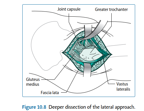
Figure 10.8 Deeper dissection of the lateral approach. downstroke of the T lying in line with the femoral neck and the bar of the T running under the femoral head (Figure 10.8). Dislocation and retractor positioning
This must be done gently as excess force can fracture the femur (typically a spiral fracture running from the subtrochanteric region down the shaft). In younger patients, the ligamentum teres can remain intact, preventing full dislocation; if this occurs it can be first divided with a scalpel. If the dislocation is difficult, further capsule can be excised, visible labrum can be removed and any acetabular osteophytes can be excised with nibblers or an osteotome. If the hip can still not be removed with minimal force, division of the femoral neck in situ with a double neck cut and removal of the head with a corkscrew are recommended.
8. Posterior approach dislocation and retraction : Hip joint dislocation is performed by placing the hip in adduction and flexion then gently internally rotating it till
dislocation, ending up with the calf lying vertically and the sole of the foot facing the ceiling. A bone hook can be carefully passed around the femur, at the level of the lesser trochanter, and used to ease the femoral head away from the acetabulum.
9. Lateral approach dislocation and retraction : The hip can be dislocated with adduction,
flexion and external rotation, again with a blunt bone hook around the femoral neck. The leg is then placed in the leg bag, i.e. the foot pointing to the floor, on the opposite side of the operating table.
Procedure
Structures at risk
1. Femoral neurovascular bundle nerve – injudicious placement of anterior retractors
2. Sciatic nerve – vulnerable posteriorly
3. Obturator arterial branches – large branches are present below the transverse acetabular ligament; cutting them should be avoided
Hohmann retractors are inserted around the superior and inferior aspects of the femoral neck, supporting and stabilising the proximal femur and exposing the whole of the intertrochanteric line. Any soft tissues along this line are removed until the superior portion of the lesser trochanter is seen or at least easily palpable. The planned femoral neck osteotomy site is marked with diathermy or an osteotome. A number of hip replacement sets have a specific instrument to aid identification of the correct site and orientation for this osteotomy; use of a trial prosthesis or a rasp as a guide is recommended in those sets without a neck cutting guide. This is particularly important with collared stems. Pre-operative templating will have provided a guide to the height above the lesser trochanter that the osteotomy should pass through the calcar. An oscillating saw is used to perform the osteotomy, with the Hohmann retractors protecting the surrounding soft tissues. If the line of the osteotomy passes into the greater trochanter, the osteotomy is stopped before entering the trochanter and a second osteotomy is performed vertically down from the piriformis fossa to meet the lateral extent of the first osteotomy (Figure 10.9). The femoral head is removed and can be utilised as autograft. 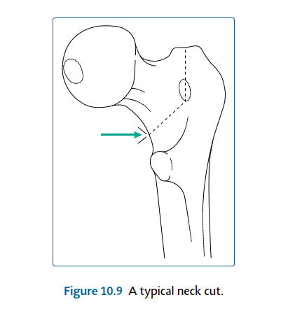


Figure 10.9 A typical neck cut.
Acetabular preparation
Any soft tissues overhanging the acetabulum around its circumference, including the labrum, are excised. It is vital to obtain a clear view around the whole acetabulum. The transverse acetabular ligament is identified, lying across the inferior boundary of the acetabulum. Any remaining ligamentum is also excised. Preservation of the transverse acetabular ligament (TAL) is advocated by most surgeons.
The TAL provides an indication of the acetabular version, and it helps to prevent inferior cement extrusion when implanting a cemented cup. If using the posterior approach, sharp Hohmann retractors are placed over the anterior wall, to lever the femur anteriorly, and under the TAL to expose the whole acetabulum for its preparation. If using the lateral approach, the proximal femur is levered posteriorly rather than anteriorly.
Within the acetabulum the medial wall or floor is defined which is sometimes visible as a flat plate of cortical bone. If it is not seen, then, it is likely to be covered in osteophytes or soft tissues, which should be removed with diathermy, an osteotome or curette to reveal the floor. This is an important step as definition of the medial wall allows proper and safe ‘medialization’, providing maximum cover of the cup when it is inserted.
Sharp, hemispherical, cheese-grater reamers are now used to remove the remaining acetabular cartilage and expose subchondral bone. Beginning with the smallest reamer, reaming is directed medially and checked regularly to ascertain the depth of reaming. The desired depth is up to, but not through the true medial wall (the flat cortical bone of the quadrilateral plate). The acetabulum is now enlarged with increasing sizes of reamers, not increasing the depth but just the width. This is performed in the desired alignment of the acetabular component to be inserted. The appropriate alignment is 40°–45° from the horizontal and 15°–20° of anteversion(Figure 10.10). The aim is to create a hemisphere, removing all cartilage but preserving as much subchondral bone as possible.
(a)
(b)
40–45°
10° to 20°


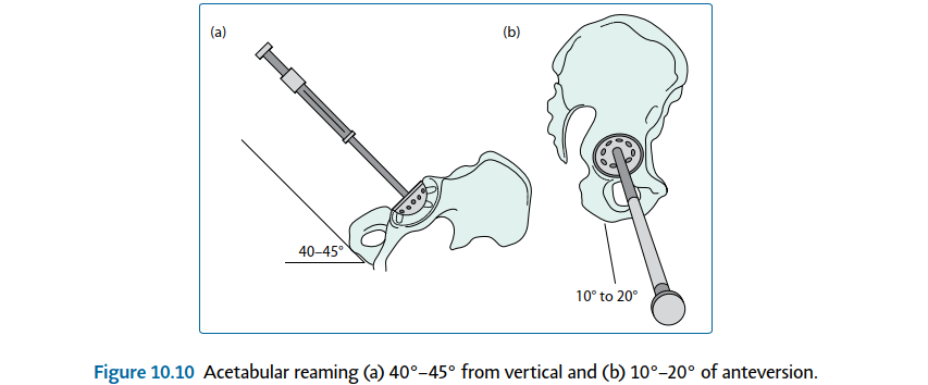
Figure 10.10 Acetabular reaming (a) 40°–45° from vertical and (b) 10°–20° of anteversion.
If the acetabular component to be used is of uncemented design, a trial cup can be inserted at the correct angle to assess the coverage and stability.
Cemented cups can also be trialled to ensure an adequate cement mantle around the implant.
At this point any osteophytes around the acetabulum (that may lead to impingement) are often apparent. These can be removed with nibblers or an osteotome. The component is inserted using the appropriate technique. It is worthwhile at the point of cup implantation, to ensure that the pelvis has remained vertical. Malposition of the patient could in turn cause angulation of the implant, with consequent risk of instability.
Technical points in uncemented cup insertion
10. The uncemented cup relies on a secure fit to confer initial stability.
11. In the press-fit technique an implant 1–2 mm larger than the last reamer is used. This can be augmented with screws as necessary.
12. The line-to-line technique uses an implant of the same size as the last reamer and relies on augmentation with screws to obtain fixation.
13. If fixation is not solid and stable, even after screws have been used, changing to a cemented cup is recommended.
14. Screw holes are aligned to coincide with the safe zone, described later. Pilot holes should be drilled, their depth ascertained with an angled depth gauge and screws inserted with a universally jointed screwdriver and a screw holder to control the direction of the screw.
15. Screw augmentation, if to be used, should be done with care and awareness of the safe quadrants. The safe quadrants, as depicted inFigure 10.11, are created by drawing two lines through the middle of the acetabulum. The first line is drawn from the anterior superior iliac spine through the centre of the acetabulum, and the second line is drawn perpendicular to this line (Figure 10.11). Safe zone Risk: Sciatic nerve superior gluteal nerve and vessels
Posterior Superior
ASIS
Posterior Inferior
Safe if screws <20mm Risk: Sciatic nerve inferior gluteal
nerve and vessels internal pudendal nerve and vessels
Anterior Superior
Risk: External illiac artery and veins Avoid screws Anterior Inferior
Risk: Anterior inferior obturator nerve artery and vein Avoid screws 


Figure 10.11 The quadrants of acetabular screw positioning. (Redrawn with permission from Miller,
Review of Orthopaedics. Philadelphia, PA: Saunders; 2004.)
Structures at risk
Posterior superior – the safe zone
1. At risk – sciatic nerve and superior gluteal neurovascular bundle Posterior inferior – safe if screws less than 20 mm
2. At risk – inferior gluteal and internal pudendal neurovascular bundles
Anterior superior – avoid screws
1. At risk – external iliac vessels Anterior inferior – avoid screws
2. At risk – anterior inferior obturator neurovascular bundle
When all of the screws are properly seated, the liner can be inserted. If using a polyethylene liner, a 10° or 20° elevated rim can be selected and orientated as desired. It should be remembered however, that this reduces the arc of motion and therefore may negatively contribute to hip stability.
Trials are available and should be used if there is any doubt. It is usual for the elevated lip to be situated posterosuperiorly or more posteriorly if a posterior approach has been used.
Technical points in cemented cup insertion
16. Many acetabular components have a lip augment, which should be correctly orientated in the posterior to superior area. If the cup has a flange (which can help to prevent cement extrusion), this will need to be trimmed to the size of the reamed acetabulum.
17. Drill holes (keyholes) should be created into the ilium and ischium, but not the quadrilateral plate, to enhance the cement fixation. The bone surface is washed with pulsatile lavage and dried thoroughly. Many acetabular components have pegs on the medial surface; these are designed to ensure a uniform cement mantle of around 3 mm.
18. The cement should be introduced from a cement gun with a short nozzle. It is first introduced to the keyholes in the ilium and ischium. This is done with the nozzle hard against the bone, to increase the pressure. It is then introduced to the rest of the acetabulum and pressurised with an impactor: most sets have a polypropylene impactor to pressurise the cement into the acetabular bone.
19. The surgeon should be aware of the specific properties of the cement that is being used to ensure that the cement and component are inserted at the appropriate time. It is vital that the component is held perfectly still while the cement is curing. Care should be taken to ensure that the cup introducer is able to be released without undue force, to reduce the stresses on the cement to component interface.
20. Any excess cement should be removed.
Femoral preparation
For the posterior approach the assistant extends and internally rotates the hip while supporting the leg with the knee flexed. For the anterior approach, the leg is maximally adducted and the hip externally rotated; the knee is flexed to position the lower leg in the leg-bag drape. An entry point is created in the proximal femur, with a box chisel, to allow the insertion of reamers; it must be correctly situated to prevent varus malposition of the component. The starting point is further posterior than anterior, to allow for the anterior bow in the femur. It must also be lateral, so that it lies directly over the lateral margin of the medullary canal (Figure 10.12). This allows instruments to run towards the medial femoral condyle, Anterior
Posterior
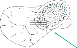
Figure 10.12 The box chisel ‘starting point’ in femoral preparation.
preventing varus malpositioning of the femoral component. This usually gives a starting point that enters the proximal portion of the greater trochanter.
The femur is initially prepared with a tapered reamer to remove a cone of medullary bone within which rasping can begin. The smallest reamer is first inserted into the medullary canal. The reamer is allowed to run down the lateral cortex, thus following the medullary canal, but the tip of the reamer should be angled slightly medially, as if trying to come out through the medial femoral condyle. This is, again, to prevent eventual varus malposition of the femoral component. If the reamer will not follow the canal, further bone needs to be removed from the greater trochanter. The entry point position and angle should be checked and adjusted if necessary. Sequentially larger tapered reamers are then used to increase the diameter, until contact with cortical bone is felt.
The next step is shaping of the proximal femur to receive the implant, whether it is to be cemented or uncemented, with particular care paid to the anteversion of the rasp within the proximal femur. This is performed with implant-specific rasps. The rasps are positioned to provide around 15° of anteversion. In the posterior approach, this is done by angling the medial side of the rasp downwards 15°; in the lateral approach it is angled 15° upwards.
Sequentially larger rasps are used to the point where stability can be achieved with the definitive component.
Technical points in uncemented stem insertion
21. The rasps used are specific to each stem design.
22. The version of the rasp must be precisely controlled throughout rasping.
23. A small rasp is used to begin with and the size increased until stability is achieved.
24. Impaction is with controlled hammer blows, watching the progress of the impactor.
25. When the rasp stops progressing, it should not be impacted further as this may lead to proximal femoral fracture. When stable, the rasp is a tight fit within the canal and rotation of the component rotates the femur with no ‘toggle’ between the two.
26. The templated size should be borne in mind.
27. Selection of a prosthesis several sizes smaller than that achieved on templating is usually due to varus alignment of rasps or may indicate excessive anteversion.
28. The depth of the rasp is noted. This should be such that the cutting teeth are at or just below the level of the neck cut.
29. Trial reduction is carried out, with a variety of offset options available on most uncemented systems (see later for details).
30. The rasp is removed and the definitive prosthesis can be inserted, following the version of the rasps. An attempt at changing the version of the stem at this point is likely to cause a femoral fracture.
31. The canal is not washed out, as the bone swarf aids in union across the implant to bone interface.
Technical points in cemented stem insertion
32. The rasps allow for a 2–3 mm cement mantle to be created between the component and bone. The technique is similar to that used for uncemented stems, with increasing rasp size until stability is achieved.
33. If using a collared stem, the final broach is sunk to the required depth and the ‘calcar cutter’ is used. This attaches over the final rasp and provides a smooth, stable neck cut at the level upon which the collar will be supported.
34. The height of the final rasp can be gauged in respect to both the greater trochanter and the medial extent of the femoral neck cut. It is vital to be able to reproduce these relationships with the definitive stem, when it is cemented in situ.
35. Trial reduction is carried out (see later for details).
36. A cement restrictor is used to occlude the medullary canal distally. The depth of insertion is obtained by measurement against the final rasp used, aiming for 1–2 cm of clearance to allow for distal cementing. The canal must now be thoroughly washed
with pulse lavage, using a long nozzle and a brush to clean debris and fat from the entire length of the prepared bone. Suction is used to remove the saline cleaning solution. The canal is then dried and packed with swabs or a preformed absorbent sponge.
37. Cementation is performed with a double mix of polymethylmethacrylate cement, using a cement gun with a long nozzle. The cement is introduced when it is of sufficient viscosity (when the cement does not stick to the surgeon’s glove, the required viscosity has been reached – typically after around 2–3 minutes).
38. The nozzle is introduced up to the cement restrictor and then cement is pumped firmly to introduce it into the canal. The cement gun is not withdrawn, rather it is allowed
to be pushed out by the cement as it fills the canal. Use of suction removes the fluid extruded from the canal.
39. When the cement reaches the proximal femur, the nozzle is withdrawn and cut. A proximal cement pressuriser is placed over the remaining nozzle and reintroduced into the femoral canal, occluding the proximal femur. Further cement is introduced under pressure, as the restrictor occludes the femoral cavity, for around 30 seconds.
40. The definitive stem should be checked and correctly assembled on its introducer. The correct time for introduction of the stem is determined by the type of cement and ambient temperature conditions. It is usually at around 4–6 minutes. The femoral component is introduced in the correct version and manually inserted to the correct depth. The version must remain constant and the insertion manoeuvre is a smooth, even application of force. The end result should be a reproduction of the depth of the trial at time of rasping. Removing the stem introducer should be done carefully so as not to toggle the stem while the cement is still setting.
41. The implant must be held perfectly still within the femur until the cement has cured, typically after 10–12 minutes.
Trialling and reduction
Trial reduction is a vital step in performing a THA. The assessment is essentially of stability, range of motion and leg length.
Reduction is carried out with appropriate trial components, usually consisting of the last rasp left in situ and a trial head. Reduction is via the surgical assistant applying in-line traction followed by rotation of the head into the acetabulum. The traction is assisted by the surgeon pushing on the femoral head with a conical pusher. If reduction cannot be achieved, a shorter femoral head and/or a neck with less offset is selected and the manoeuvre repeated.
The position of the head with respect to the greater trochanter is noted and compared with preoperative templating.
The hip is passed through a functional range of motion and must not dislocate in any position. The hip can then be forced into non-physiological positions to assess the point at which dislocation can occur. In the lateral approach, the hip should remain in joint even when the leg is replaced in adduction and external rotation, back into the sterile ‘leg bag’. In the posterior approach, the hip is tested in flexion, slight adduction and forced internal rotation; the degree of internal rotation to dislocation should be noted and should be no less than 40°.
The tissue tension is assessed by the ‘shuck test’ – the femur is pulled sharply downwards and the degree of telescoping of the femoral head away from the acetabular socket is noted. Any more than a few millimetres of movement suggests that instability may be present. In this case, a longer trial femoral head may be required.
The lateral tissue tension can be assessed with the ‘lateral shuck test’. A dislocation hook is passed around the femoral neck and the component sharply pulled laterally. Again, excessive movement suggests instability, and a greater amount of offset may be required.
The operated leg is placed against the opposite leg in order to compare leg length. Gross differences suggest incorrect tissue tension. Note that stability and range of motion are of higher importance than subtle differences in leg length; however, lengthening of the operated leg to greater than 1 cm longer than the other leg is associated with significant patient dissatisfaction.
If a stable hip is not achievable in a functional range of motion, consideration must be given to the following factors:
42. Component position – are the stem and cup components in the correct degree of version? Is the cup sufficiently medialized? Is the stem at the correct height? Repositioning one or both components may be required to achieve stability.
43. Use of a lip augment on the acetabulum. In uncemented acetabula, exchange of the liner is relatively simple. The use of a 10° or 20° lip augment can improve hip stability.
44. Use of a larger femoral head will increase the stability of the hip.
45. The use of a constrained prosthesis is a last resort and is not usually appropriate in primary hip surgery.
Closure of posterior approach
If the capsule has been preserved, it is sometimes possible to repair this directly, using a heavy absorbable suture. Proper repair of the short external rotators to the femur is vitally important. The rotators should be intact and easily identified by the sutures passed through their tendons prior to their division. If these sutures are left long at the time of their insertion, they can be used to reattach the muscles. If not, four sutures are secured to the cut ends of the short external rotators. A small (e.g. 2.5 mm) drill is used to create bone tunnels through the greater trochanter, from anterior to posterior, in the line of attachment of the short external rotators (Figure 10.13). A suture passer can be used to pull one of the sutures through – both ends of the same suture are pulled through the one hole. Three further drill holes are created and the three remaining sutures pulled through. 4 drill holes


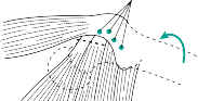
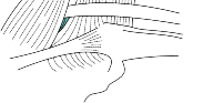
Figure 10.13 Position of drill holes for reattachment of the short external rotators.
Both ends of the upper two sutures are then tied to each other, then the same procedure is carried out with the lower two sutures. This is done with the leg in around 10° of abduction and only a few degrees of external rotation, which allows approximation of the tendon to the greater trochanter without causing a fixed rotation deformity. The split fibres of the gluteus maximus are loosely approximated with absorbable sutures.
If a surgical drain is to be used, it is inserted now. Closure of the fascia lata is performed with the hip in slight abduction. Superficial closure utilises absorbable sutures to approximate the subcutaneous fat, then cutaneous sutures or surgical staples. An occlusive dressing is applied.
Closure of lateral approach
If the capsule is repairable, this is performed first. The gluteus medius anterior and posterior flaps are approximated. These are then tightly sutured together with the leg in around 10° of abduction.
Superficial closure follows the same technique as that for the posterior approach.
Postoperative care and instructions
The patient is returned to the supine position and an abduction pillow can be inserted between the legs. Any straps present on these pillows should not be used, due to the risk of peroneal nerve damage. Precautions against thromboembolism should be used. Common options include aspirin, low molecular weight heparin, graduated compression stockings and foot or calf intermittent compression pumps. Early mobilisation should be encouraged in all patients.
Dependent on local guidelines, 24-hour antibiotic coverage can be considered. Haemoglobin levels should be monitored and transfusion considered as necessary.
In general, full weightbearing is encouraged following cemented, uncemented and hybrid THAs. Cautious weightbearing may be considered if an intraoperative fracture has occurred. The patient is asked to avoid crossing of the legs or excessive flexion of the hips. To this end, they are provided with a raised toilet seat and instructed to avoid low seats. Particular care is recommended when putting on socks and shoes – a common cause of early dislocation. Return to work is allowed after around 6 weeks for sedentary jobs, but may be delayed to 3 months or more in active work. Follow-up is recommended at 6 weeks, 6 months and 1 year after surgery. Continuation of follow-up is typically at 5 years, 10 years, 15 years and then at yearly intervals. The patient should be encouraged to return to clinic if they experience pain or functional deterioration.
Recommended
Scientific References
-
Barrack RL, Mulroy RD Jr, Harris WH. Improved cementing techniques and femoral component loosening in young patients with hip arthroplasty. _J Bone Joint Surg Br_. 1992;74:385–389.
Charnley J. Arthroplasty of the hip: A new operation. _Lancet_. 1961;1:1129–1132. Hardinge K. The direct lateral approach. _J Bone Joint Surg Br_. 1982;64:17–19.
Lidwell OM, Lowbury EJ, Whyte W et al. Effect of ultraclean air in operating rooms on deep sepsis in the joint after total hip or knee replacement. _BMJ_. 1982;285:10–14.
Murray DW, Carr AJ, Bulstrode CJ. Which primary total hip replacement? _J Bone Joint Surg Br_.
1995;77:520–527.
Pellicci PM, Bostrom M, Poss R. Posterior approach to total hip replacement using enhanced posterior soft tissue repair. _Clin Orthop Relat Res_. 1998;**(355)** :224–228.
[National Joint Registry. ](http://www.njrcentre.org.uk/)[http://www.njrcentre.org.uk](http://www.njrcentre.org.uk/)
[Revision total hip arthroplasty](file:///C:/Users/DELL/Desktop/hip/quick%20fact/10.%20Surgery%20of%20the%20Hip_Converted.html#bookmark12)
This section refers extensively to the previous section and is not intended as a stand-alone text to enable all surgeons to revise all hips. It aims to provide some useful directions as to appropriate techniques that can be applied to solve some problems, but cannot cover all potential problems.
Preoperative planning
_Indications_
Revision hip arthroplasty is indicated for failure of a primary hip arthroplasty. The most common causes are
- 46. Aseptic loosening of the socket and/or stem [View Source / PubMed]
- 47. Deep infection (see later section) [View Source / PubMed]
- 48. Instability, resulting in recurrent dislocation [View Source / PubMed]
- 49. Fracture of either the implant, proximal femur or the acetabulum _Contraindications_ [View Source / PubMed]
- 50. Continuation of preoperative pain after hip arthroplasty (suggests that the original diagnosis may have been wrong and warrants further investigation). [View Source / PubMed]
- 51. Pain-free radiographic loosening is a relative contraindication, except in cases associated with significant and progressive osteolysis. _Consent and risks_ [View Source / PubMed]
- 1. Nerve injury: 3%–7% [View Source / PubMed]
- 2. Infection: Quoted up to 30%, 5% is a more commonly accepted figure [View Source / PubMed]
- 3. Thromboembolism: 3% [View Source / PubMed]
- 4. Dislocation: 7% [View Source / PubMed]
- 5. Aseptic loosening: 10%–30% at 10 years [View Source / PubMed]
- 6. Fracture [View Source / PubMed]
- 7. Limb length discrepancy _Operative planning_ Revision arthroplasty is more challenging than primary hip arthroplasty, so it requires even more precise planning. Recent radiographs are essential. ‘Judet views’ can be very helpful in assessing acetabular bone loss. If there is significant bone loss, a fine-cut computed tomography (CT) scan can be used to assess and quantify this. The patient should have been seen in outpatients recently so that the clinical and functional status can be formally assessed. This is as vital as the osseous imaging in decision-making. The soft tissue status must be assessed and any signs of infection warrant investigation and treatment. It is not always necessary to reviseallcomponents in aseptic failures; consideration should be given to retaining any well-fixed and functional prosthetic component. If the prosthesis is infected, usually a two-stage procedure is preferred (see later). Templating should be carried out with great care. It is necessary to be prepared for unexpected findings at the time of surgery and a wide range of implants should be available to the surgeon. There are a number of extra instruments and pieces of equipment which can be useful in revision procedures: [View Source / PubMed]
- 52. Image intensifier [View Source / PubMed]
- 53. Implant-specific extraction instruments for the existing THA [View Source / PubMed]
- 54. Bone allograft, for morcellized or block grafting [View Source / PubMed]
- 55. Cement removing osteotomes and ultrasonic cement removal systems [View Source / PubMed]
- 56. Supplementary metalwork, including cabling systems, trochanteric fixation devices, acetabular reconstruction rings and plates, cages, mesh and even computer-aided design/computer-aided manufacturing (CAD/CAM) implants [View Source / PubMed]
- 57. Universal modular neck adaptors for worn trunnions or to change stem offset and version. [View Source / PubMed]
- 58. Thin, curved osteotomes for removing uncemented hips: [View Source / PubMed]
- 1. Explant acetabular cup removal system [View Source / PubMed]
- 2. High-speed burr/cebotome [View Source / PubMed]
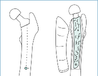
- 3. Flexible femoral canal reamers _Anaesthesia and positioning_ This is usually the same as in primary arthroplasty, bearing in mind the procedure is likely to take considerably longer. Also initial antibiotic dose is usually delayed until after microbiological samples have been taken. Surgical technique _Approach_ Either the posterior or lateral approach can be used. Some surgeons argue that the posterior approach is best for posterior acetabular defects. [An extended trochanteric osteotomy can be beneficial particularly when needing to remove a well-fixed stem or there is a risk of trochanteric fracture during the surgical approach. The greater trochanter is osteotomised with gluteus medius and vastus lateralis attached, allowing it to be mobilised well out of the way. The length of the osteotomy required is dependent on the length of the stem and may be as long as the implant itself, which can be judged with image intensifier or from preoperative planning (](file:///C:/Users/DELL/Desktop/hip/quick%20fact/10.%20Surgery%20of%20the%20Hip_Converted.html#bookmark34)[Figure ](#bookmark34)10.14).   Figure 10.14 An ‘extended’ trochanteric osteotomy. Identification of the sciatic nerve is important, particularly in the posterior approach. The nerve can be isolated by carefully passing a vascular sloop around it, thus ensuring that its location is known at all times. _Procedure_ Following dislocation, the femoral head of a modular component is removed with a head and neck separator. Many implants have a specific extraction device and, if available, these should be used. _Removal of a cemented stem_ It is sometimes possible to simply pull the implant out of the cement mantle. If this is not the case, some of the proximal cement mantle will need to be removed, particularly from the lateral margin of the implant. This is almost always necessary if removing a curved femoral stem. This can be achieved with cement osteotomes or a high-speed burr. The rest of the cement can be left _in situ_ at this time as it tamponades bleeding from the femoral canal and may reduce the chances of femoral fracture during acetabular exposure. When cement is to be removed, it can be done with cement osteotomes and an ultrasonic cement remover. The cement restrictor must also be removed. _Removal of an uncemented stem_ This can be very difficult in well-fixed stems, particularly if extensively coated. The use of specialised, flexible osteotomes, K-wires or high-speed burs is recommended. Care must be taken to avoid unnecessary breach of the proximal femoral cortex. Following removal, the femoral canal is packed with swabs to tamponade bleeding. _Assessing femoral bone loss_ _[The two most commonly used grading systems are the Paprosky and the American Academy of Orthopedic Surgeons (AAOS) systems.](file:///C:/Users/DELL/Desktop/hip/quick%20fact/10.%20Surgery%20of%20the%20Hip_Converted.html#bookmark35)[Table ](#bookmark35)10.1 shows the Paprosky system together with possible reconstructive solutions._ _Removal of a cemented socket_ If the acetabular component is loose, it will often come free with minimal effort, typically along with the majority of its cement attached. In a well-fixed socket, a curved osteotome is used to develop a plane between the cup and the cement. Alternatively, a pilot hole can be drilled into the centre of the component and a slap-hammer screwed into it. Once loose, the socket is removed and the cement is then removed piecemeal with small osteotomes. This method ensures the least amount of bone loss and minimises the likelihood of acetabular fracture. If this method also fails, the acetabular socket can be cut into quarters with a power saw and can then be removed. It is important that all cement is also removed. _Removal of an uncemented socket_ If the cup is well fixed, it should be remembered that it may not need to be removed. In this case, the liner can be removed, but this must be done carefully to avoid damage to the cup-to-liner locking mechanism. If the locking mechanism is still functioning, a simple liner exchange can be performed, remembering that the replacement liner need not be of the same internal diameter or have the same augment or ‘lip’ size. An alternative measure, _Table 10.1 Paprosky classification of femoral defects at revision hip surgery_ | Paprosky grade | Diagram | Treatment options | | --- | --- | --- | | _Type I – has an intact metaphysis and isthmus_ | | Typically treated with a primary implant _Type II – has metaphyseal damage but an intact isthmus_ | | Long stem cemented implant; distally fixed uncemented stem _Type IIIA – distal fixation can be achieved at the isthmus, despite damage to the isthmus and the metaphysis_ | | Long stem cemented implanted with impaction allograft; long stem distally fixed uncemented stem _Type IIIB – damage to the metaphysis and isthmus prevent distal fixation from being achieved_ | | Long stem cemented implant with morcellized and corticocancellous strut graft; long stem distally fixed uncemented stem with corticocancellous strut graft; massive tumour prosthesis proximal femoral replacement _Type IV – extensive metaphyseal damage and an eroded isthmus_ | |  Proximal femoral replacement in a well-fixed socket with a destroyed or obsolete locking mechanism, is cementation of a smaller liner within the shell. If the shell is to be removed, any screws are removed first. The well-fixed cup is carefully removed by developing a plane between the bone and the implant with curved osteotomes or a suitable removal system, such as Explant (Zimmer, Warsaw, Indiana). In either case, care must be taken to minimise bone destruction and avoid excess bone loss. _Assessing acetabular bone loss_ [The most commonly used grading systems are the Paprosky and AAOS systems. ](file:///C:/Users/DELL/Desktop/hip/quick%20fact/10.%20Surgery%20of%20the%20Hip_Converted.html#bookmark36)[Table 10.2](#bookmark36) shows the AAOS grading system together with possible reconstructive solutions. Revision of infected implants If the revision is for infection, this can be performed as either a single-stage or a two-stage procedure. Two-stage revision is believed to result in lower re-infection rates but may result in significant functional impairment. In appropriately selected patients, single-stage revision can be associated with similar reinfection rates when compared with two-stage revision with superior functional outcomes. For a two-stage procedure, the initial stage is removal of all implants and cement. It is vital that multiple samples (usually five) from around all implants are sent for microbiological assessment. The whole surgical field should be thoroughly debrided and then washed out with a minimum of 6 L of saline pulsatile lavage. A polymethylmethacrylate cement spacer is then inserted. This can be preformed or can be made with moulds of varying sizes. The cement should contain heat-stable antibiotics, such as gentamicin or tobramycin. Closure is performed and the patient may mobilise, although usually only partially weightbearing. The patient should be followed up clinically and have regular checks of inflammatory markers. Postoperative antibiotics can be given once the microbiological sensitivities have been received. These cases often require combination antibiotic therapy and should be managed together with a microbiologist. Once the inflammatory markers are normal, the second stage can be undertaken, with reconstruction depending on the extent of femoral and acetabular bone loss. Particular care must be taken with the soft tissues as multiple procedures will often have taken their toll on the surrounding musculature. Many surgeons prefer the use of a cemented stem in this situation as extra antibiotics can be added to decrease the chance of recurrence. Some surgeons may opt to perform a single-stage revision in selected patients, which involves a thorough debridement, removal of implants and re-implantation of definitive prosthesis at the same time. Whichever approach is taken it is important to manage these complex patients within a multidisciplinary team structure consisting of orthopaedic surgeons, plastic surgeons and microbiologists. _Table 10.2 American Academy of Orthopedic Surgeons (AAOS) classification of acetabular bone loss at revision hip surgery_ | AAOS grade | Diagram | Treatment options | | --- | --- | --- | | Segmental | |  |    Small defects, allowing for 70% implant to bone contact, require no additional treatment; larger defects can require the use of structural allograft or asymmetric acetabular shells, e.g. the S-ROM oblong (DePuy, Warsaw, Indiana); loss of the medial wall can be managed with a malleable mesh and morcellized allograft as long as there is peripheral support. Cavitatory | |  If small, these are usually reamed to provide contact in 70% or more of the bone surface. An uncemented cup with screw augmentation is a typical prosthesis used; larger defects require grafting – this can be with morcellized graft obtained from fresh frozen femoral head allograft. It can need structural graft, again usually obtained from femoral head or distal femoral allograft, fixed with _screws_ or a buttress plate. Combined | |    The segmental defect is first reconstructed to provide a stable rim; persisting cavitatory loss is grafted with morcellized allograft. Pelvic discontinuity | |  This is a difficult problem, requiring reconstruction with plates and screws or even an entire acetabular allograft; CAD/CAM sockets can be very useful to provide fixation to the ilium, ischium and pubis. _Abbreviations: CAD/CAM, computer-aided design/computer-aided manufacturing._ Closure and postoperative care These are broadly in line with the guidelines for primary hip arthroplasty. It may be necessary to consider additional precautions, particularly in limitation of range of motion and weightbearing. It is usual to continue antibiotics until microbiological results are available. Recommended references Gruen TA, McNeice GM, Amstutz AC. ‘Modes of failure’ of cemented stem-type components: A radiographic analysis. _Clin Orthop Relat Res_. 1979;(141):17–27. Jasty M, Harris WH. Total hip reconstruction using frozen femoral head allografts in patients with acetabular bone loss. _Orthop Clin North Am_. 1987;18:291–299. Valle CJ, Paprosky WG. Classification and an algorithmic approach to the reconstruction of femoral deficiency. _J Bone Joint Surg Am_. 2003;85(Suppl 4):1–6. [Hip resurfacing](file:///C:/Users/DELL/Desktop/hip/quick%20fact/10.%20Surgery%20of%20the%20Hip_Converted.html#bookmark14) Hip resurfacing can be technically more challenging than a primary THA but shares many similar principles. Preoperative planning _Indications and contraindications_ The indications and contraindications of hip resurfacing are almost the same as those for THA. In addition, there are further contraindications that reflect the need to maintain the femoral neck: [View Source / PubMed]
- 1. Femoral head cysts greater than 1 cm diameter [View Source / PubMed]
- 2. Osteoporosis – recommended to investigate with dual-energy X-ray absorptiometry (DEXA or DXA) in perimenopausal women/high-risk groups [View Source / PubMed]
- 3. Neck length of less than 2 cm [View Source / PubMed]
- 4. Significant lateral head-neck remodelling [View Source / PubMed]
- 5. Head:neck ratio less than 1.2 _Consent and risks_ [View Source / PubMed]
- 1. The consent process and risk profile are equivalent to THA. [View Source / PubMed]
- 2. In addition the risks of femoral neck fracture or intraoperative conversion to THA (e.g. due to notching or size mismatch) must be mentioned. _Operative planning_ Performing up-to-date radiographs and preoperative templating are essential. The surgeon should have a guide available to check the compatibility of the femoral and acetabular components. _Anaesthesia and positioning_ This is performed as for THR. Surgical technique Surface replacement is possible through any of the common approaches to the hip. The posterior approach is commonly used, and the following description describes this approach. The dissection is exactly as described in the THA section. In order to gain visibility around the whole of the femoral neck, some further steps are applied: [View Source / PubMed]
- 6. The quadratus femoris should be released prior to dislocation. [View Source / PubMed]
- 7. The gluteus maximus tendon can be released off its insertion into the linea aspera, allowing more rotation and visualisation. [View Source / PubMed]
- 8. The capsular incision is much more significant. This is essential in order to allow 360° visualisation of the neck to check that notching is not going to occur. [View Source / PubMed]
- 9. The capsulotomy is carried out from superior to inferior around the femoral neck, carrying on down the inferior neck as far as can be visualised. [View Source / PubMed]
- 10. This incision is then carefully continued with heavy ‘capsulotomy’ scissors, releasing the capsule inferiorly and medially. Great care is taken to stay close to the bone of the femoral neck. [View Source / PubMed]
- 11. [The hip is dislocated and the capsulotomy continued until the capsule is released right around the femoral neck, such that the head and proximal femur can be viewed all the way around (](#bookmark38)Figure 10.15).        Figure 10.15 Extensive release of the hip capsule to allow full delivery of the femoral head into the wound. _Femoral head displacement_ In order to adequately visualise the acetabulum, the femoral head must be displaced. If there are any particularly large osteophytes, these should be removed at this stage. A pocket is created for the femoral head, lying under the gluteus medius and upon the iliac wing above the acetabulum. This can be created by sweeping a blunt periosteal elevator or bone spike under the gluteus medius. Once a sufficient pocket is created, the leg is lowered sufficiently to place a sharp retractor over the anterior lip of the acetabulum. This is used to lever the femur anteriorly as the leg is dropped down onto the table, and the femoral head is guided into the pocket already created. If the head is very large, it can be debulked further by the initial stages of femoral head preparation (described later) prior to displacing it into the pocket. _Acetabular preparation_ This is very similar to the technique described in the section on THA for uncemented cup insertion and the position is the same. Care should be taken not to over-ream the acetabulum as the implants are press-fit and cannot be augmented with screws. In addition, selection of the femoral head size is guided by the size of the acetabular component as they must fit together. _Femoral preparation_ Femoral shaping is done to create a cut surface that will fit with the femoral component. A variety of jigs are available depending upon the implant manufacturer, and reference to the individual technical guides is recommended. They all aim to place a guide wire in the centre of the neck, in both the anteroposterior and mediolateral planes. The fovea does not correspond to the midpoint of the neck so the entry point will be some way above this. This critical step can be helped by drawing a line up the centre of the posterior and lateral margins of the neck and carrying this up onto the head as a guide. The position to aim for is equal to the native anteversion and 0–10° of valgus compared with the patient’s femoral neck. Once the guide wire is passed, a jig is placed over it and swept around the entire neck to ensure that there is clearance around the whole diameter, i.e. it will not be notched. If the entry point or angle is incorrect, the guide wire is removed and replaced. Once the guide wire is correctly positioned a post drill is used to create a central hole for the post to be inserted into the femoral head. This is then the guide for further cuts. Again, equipment varies but all have specific cutters and reamers for shaping of the proximal femur. Care should be taken to ensure the size chosen fits with the acetabular component and that notching of the neck is prevented. If a significant notch is created, the surgeon must convert to a THA. While cutting and shaping, drapes should be placed over the surrounding soft tissues to prevent bone swarf from entering tissue planes. A profile reamer is then used to shape the head and a step drill to create around six holes in the bevelled edge, to act as cement keys. The intended final resting place of the component is marked on the femoral head-neck junction. The head is thoroughly washed with pulsed normal saline and the appropriate head is cemented _in situ,_ typically with low-viscosity cement. It is impacted up to the previously created mark to ensure that it is in place. The hip is reduced and assessed for stability. Closure and postoperative care At closure, the gluteus maximus tendon and quadratus femoris are closed, then closure is as for THA. Postoperative care and rehabilitation are also equivalent to THA. [Hip arthrodesis](file:///C:/Users/DELL/Desktop/hip/quick%20fact/10.%20Surgery%20of%20the%20Hip_Converted.html#bookmark16) Preoperative planning The following is a description of one common technique although there are many described in the literature. _Indications_ Hip arthrodesis is rapidly becoming a procedure of historical interest only, as improvements in THA allow implantation in younger patients. It has limited indications now but was used in younger adults in order to allow return to manual labour. Continuing indications are [View Source / PubMed]
- 12. Failed arthroplasty [View Source / PubMed]
- 13. Sequelae of infection, particularly tuberculosis [View Source / PubMed]
- 14. Sickle cell anaemic arthropathy _Contraindications_ [View Source / PubMed]
- 15. Contralateral hip disease [View Source / PubMed]
- 16. Ipsilateral knee disease [View Source / PubMed]
- 17. Pre-existing lower back pain [View Source / PubMed]
- 18. Inflammatory arthropathy – relative _Consent and risks_ [View Source / PubMed]
- 1. Lower back pain: 60% [View Source / PubMed]
- 2. Leg length discrepancy: 100% (typically up to 5 cm) [View Source / PubMed]
- 3. Knee pain: 45% [View Source / PubMed]
- 4. Failure of fusion: 2% clinically but up to 30% radiographically [View Source / PubMed]
- 5. Malpositioning (it has been shown that the rates of back pain are higher in malpositioned hips) The patient must understand that walking will be abnormal and running impossible. There is a significant reduction in walking speed and increase in energy expenditure. _Operative planning_ Planning the position of fusion is vital. The optimum position is [View Source / PubMed]
- 19. Flexion of 20°–25° [View Source / PubMed]
- 20. Rotation neutral to 10° of external rotation [View Source / PubMed]
- 21. Adduction of 0°–5° A variety of intra-articular or extra-articular techniques can be used to achieve fusion. _Anaesthesia and positioning_ This is performed as for THA, except the patient is in a supine position with a sandbag under the ipsilateral buttock. Surgical technique _Approach_ The lateral approach to the hip is used, as described in the primary arthroplasty section. The supine position allows for more accurate assessment of leg length and, upon removal of the sandbag, the surgeon can perform a Thomas’ test at the end of the fusion in order to assess the position of arthrodesis. _Procedure_ The gluteus medius and minimus complex is left attached to the greater trochanter and their anterior and posterior borders defined carefully. An oscillating saw is used to create an osteotomy, separating the greater trochanter from the proximal femur. The abductors, proximally and vastus lateralis distally, remain attached to the greater trochanter. The greater trochanter and abductor complex are reflected upwards; this may require some dissection of the undersurface of the abductors away from the superior capsule. The bony surface around the superior acetabulum is defined by blunt dissection, revealing the sciatic notch, posteriorly and the anterior inferior iliac spine, anteriorly. A blunt Hohmann retractor is inserted into the sciatic notch (this protects the sciatic nerve and the superior gluteal vessels) and another is hooked around the iliopectineal eminence anteriorly. A horizontal osteotomy is carefully created between the two retractors, running just above the superior surface of the acetabulum. This can be started with an oscillating saw but should be completed with an osteotome to reduce the danger of sciatic nerve injury. A corresponding horizontal surface is created on the top of the femoral head by removing a small portion of the head with an oscillating saw. Curettes are used to remove any areas of persistent cartilage on the femoral head and the acetabulum. A retractor is inserted into the pelvic osteotomy and used to lever the osteotomy and displace the distal portion approximately 1 cm medially with respect to the proximal ilium. By removing the sandbag from under the buttock, the position for arthrodesis can be accurately assessed. The cobra plate is attached over the osteotomy site; this only requires one screw into the pelvis and one into the femur at this stage. Careful palpation of the pelvis, patella and malleoli is carried out to confirm the correct position of the leg before the arthrodesis is completed. The author recommends the use of an image intensifier at this stage to further confirm positioning. [The flexion position of 20°–25° is confirmed by performing the Thomas test. The greater trochanter is then repositioned at the anatomical site. This can now be attached back onto the femur with a screw through the greater trochanter and the cobra plate (](#bookmark40)Figure 10.16). The remaining screw holes are drilled and further cortical screws inserted to strengthen the arthrodesis. _Closure_ Similar to lateral approach for THA. Postoperative care and instructions Thromboembolism should be prevented by early mobilisation and the addition of chemical and mechanical measures in patients at increased risk. Two further doses of the antibiotic given at induction should be given at 8 hours and 16 hours after surgery.  Figure 10.16 A hip arthrodesis with cobra plate. Early mobilisation is non-weightbearing, with the aid of crutches. Radiographic signs of union are sought before a return to weightbearing is allowed. This often takes around 3 months. If the patient has significant shortening, i.e. greater than 15 mm, a shoe raise can be provided and used as the patient deems necessary. Recommended references Murrell GA, Fitch RD. Hip fusion in young adults. Using a medial displacement osteotomy and cobra plate. _Clin Orthop Relat Res_. 1994;(300):147–154. Sponseller PD, McBeath AA, Perpich M. Hip arthrodesis in young patients: A long term follow up study. _J Bone Joint Surg Am_. 1984;66:853–859. [Excision hip arthroplasty (Girdlestone procedure)](file:///C:/Users/DELL/Desktop/hip/quick%20fact/10.%20Surgery%20of%20the%20Hip_Converted.html#bookmark18) Preoperative planning _Indications_ [View Source / PubMed]
- 22. It is a last resort operation and used as a salvage procedure, generally in patients with resistant infections or co-morbidities which necessitate a quick operation. [View Source / PubMed]
- 23. Sepsis of either THA or the native hip. [View Source / PubMed]
- 24. Aseptic loosening of THA. [View Source / PubMed]
- 25. Painful hip conditions in a patient otherwise immobile, particularly in degenerative neuromuscular conditions. _Consent and risks_ [View Source / PubMed]
- 1. Nerve injury [View Source / PubMed]
- 2. Limb length discrepancy: it is usually 3–12 cm, depending on resection [View Source / PubMed]
- 3. Recurrence of infection (if a septic indication): 10% [View Source / PubMed]
- 4. Nearly all will be reliant on walking aids after surgery; many have poor function but most have good pain relief _Anaesthesia and positioning_ This is performed as for THA. Surgical technique One of the approaches for THA is selected. If the hip is septic, a thorough washout and debridement of infected tissue is essential. The excision is carried out as in THA femoral head resection. All non-viable bone should be resected; however, the best functional results are achieved with a greater amount of retained proximal femur. A considered excision of bone should be performed. Postoperative care and instructions This is similar to THA in many respects. Traction is often used for the first 2 weeks after surgery. Almost all patients will require walking aids and shoe raises. [Femoroacetabular impingement surgery](file:///C:/Users/DELL/Desktop/hip/quick%20fact/10.%20Surgery%20of%20the%20Hip_Converted.html#bookmark11) Preoperative planning _Indications_ Pain and/or restricted range of motion associated with a recognised anatomical deformity. [This can be of two types: cam or pincer; these can also co-exist (](file:///C:/Users/DELL/Desktop/hip/quick%20fact/10.%20Surgery%20of%20the%20Hip_Converted.html#bookmark43)[Figure ](#bookmark43)10.17). The cam deformity of the femur is also referred to as a ‘pistol grip’ deformity. The most typical presentation is groin pain worse on prolonged flexion, e.g. sitting. The impingement test of the hip is usually positive. This is performed with the hip held in 90° flexion and passively internally rotated and adducted. _Contraindications_ [View Source / PubMed]
- 26. Active infection [View Source / PubMed]
- 27. Moderate or severe existing arthritis on radiographs _Consent and risks (as applicable to open femoroacetabular impingement surgery)_ [View Source / PubMed]
- 1. DVT: Less than 1% [View Source / PubMed]
- 2. Infection: Less than 1% [View Source / PubMed]
- 3. Femoral neck fracture: Incidence related to amount of femoral ‘bump’ removed [View Source / PubMed]
- 4. Avascular necrosis of the femoral head: Unknown incidence (many studies of open surgery show 0%) [View Source / PubMed]
- 5. Heterotopic ossification: 3% [View Source / PubMed]
- 6. Progression to frank osteoarthritis: Up to 100% Normal CAM Pincer Mixed   Figure 10.17 The common variants of femoroacetabular impingement. _Operative planning_ Recent radiographs must be available – anteroposterior (AP) views of the hip and a shoot-through lateral with the leg in maximal internal rotation best demonstrates the anatomy. Hip and impingement morphology is best demonstrated with computer tomography (CT) scan. Magnetic resonance imaging (MRI), MR arthrography or arthroscopy are often used to examine for labral pathology. Conventional arthrography and local anaesthetic injection are frequently used to provide evidence that the pain is originating in the hip. The surgeon must decide the approach to be taken. There are three common options: [View Source / PubMed]
- 28. The arthroscopic approach (see ‘Hip arthroscopy’, next section). [View Source / PubMed]
- 29. The lateral open approach, using a trochanteric flip osteotomy, as popularised by Ganz. The hip is then surgically dislocated to reveal the impingement. [View Source / PubMed]
- 30. A more recent approach has been a ‘mini-open’ modified Smith-Peterson approach. This has the advantage of visualisation without dislocation of the hip. This approach is described here. _Anaesthesia and positioning_ Anaesthesia is general with supine positioning. The use of an intraoperative image intensifier is optional. Surgical technique _Landmarks_ The anterior superior iliac spine is palpated. Slight external rotation of the hip aids location of the interval between the tensor fascia lata and sartorius. _Incision_ A 7–10 cm incision is created, running from just below the anterior superior iliac spine, along the border between the tensor fascia lata and sartorius. This incision should not stray medially into the area overlying sartorius and it is preferable to create the incision a few millimetres lateral to the border of sartorius to ensure that this does not occur. The direction of the incision is towards the lateral border of the patella. _Superficial dissection_ _Structure at risk_ [View Source / PubMed]
- 1. Lateral femoral cutaneous nerve Dissection is continued through fat and superficial fascia. The lateral femoral cutaneous nerve is identified, running over the fascia between the tensor fascia lata and sartorius. The nerve is retracted medially and the fascia incised between the two muscle bellies. This provides an interval with the muscle belly of tensor fascia lata laterally and that of sartorius medially. The dissection is continued down between the tensor fascia lata and sartorius, until the direct and reflected heads of the rectus femoris are identified. _Deep dissection_ _Structures at risk_ [View Source / PubMed]
- 1. _Femoral nerve and artery : These lie medial to the sartorius, anterior to the pectineus muscle. They will not be damaged if dissection is lateral and deep to the sartorius._ [View Source / PubMed]
- 2. _Medial femoral circumflex artery : 1 cm proximal to the lesser trochanter, underlying the_ iliopsoas tendon. If not identified and accidentally damaged, profuse bleeding can be expected. The reflected head of the rectus femoris is identified and dissected off its origin on the superior acetabular margin. Its fibres also blend with the anterior hip capsule, and these fibres are dissected free from the capsule. The direct head is retracted medially to reveal the iliopsoas tendon. This also requires dissecting free from the capsule as it is attached by the iliocapsularis tendon. Subsequently, the iliopsoas too can be retracted medially. The underlying capsule is exposed and can be incised in line with the femoral head-neck junction. This is most easily identified at the anteromedial portion of the femoral head as the impingement bump in a cam-impinging hip will prevent palpation of the head-neck junction laterally. Thus, it is advisable to begin the incision medially and proceed laterally. _Procedure_ The osteoplasty of the head-neck junction is carried out with a small (10–15 mm) osteotome or a high speed burr. An assistant internally and externally rotates the hip to allow complete excision of the cam lesion. The resection is directed distally to produce a bevelled resection, restoring the offset between the femoral head and neck. This creates a ‘V’-shaped valley over the anterior head-neck junction. The depth of the valley can be assessed by bringing the hip back into the position of the impingement test. The aim is a gain in both internal rotation and flexion of the hip by over 10°. If the valley is not deep enough, it can be further deepened in a similar manner. The aim is complete excision of the protuberant bump, until the remaining femoral head is spherical and no longer impinging on the anterior acetabular rim. Similarly, if there is evidence of pincer impingement, the acetabular osteophytes or calcified labral tissue can be removed with an osteotome and excised. Bleeding from exposed bone can be reduced by application of bone wax. The wound is thoroughly irrigated and any loose bone and cartilage carefully removed. _Closure_ [View Source / PubMed]
- 31. The capsulotomy, reflected head of rectus and tensor fascia lata-sartorius interval are all closed in a layered manner with heavy absorbable suture. Skin closure is performed as per surgeon preference. Postoperative care and instructions The patient may begin mobilisation as soon as comfortable – this should be toe-touch weightbearing, with crutches, for 6 weeks. Active flexion is avoided for 6 weeks to allow healing of the reflected head of rectus femoris. Active abduction is begun straight away. Mobilisation without crutches is slowly begun after 6 weeks. High-impact sports, including running, are not permitted for 6 months. [Hip arthroscopy](file:///C:/Users/DELL/Desktop/hip/quick%20fact/10.%20Surgery%20of%20the%20Hip_Converted.html#bookmark13) Preoperative planning _Indications_ Hip arthroscopy is indicated in a variety of painful conditions of the hip. The most frequent are [View Source / PubMed]
- 32. Femeroacetabular impingement [View Source / PubMed]
- 33. Septic arthritis of the hip joint [View Source / PubMed]
- 34. Osteoarthritis [View Source / PubMed]
- 35. Labral pathology [View Source / PubMed]
- 36. Osteochondral defect [View Source / PubMed]
- 37. Removal of loose bodies [View Source / PubMed]
- 38. Synovectomy or synovial biopsy _Contraindications_ [View Source / PubMed]
- 39. Infection of overlying skin. [View Source / PubMed]
- 40. Hip ankylosis or significant protrusion of the hip. [View Source / PubMed]
- 41. Lack of proper instrumentation. The instruments are specific to hip arthroscopy and surgery should not be attempted without fluoroscopy, appropriate portal instruments, a long arthroscope (30° or 70° angle) and distraction equipment. [View Source / PubMed]
- 42. Gross osteoarthritis is a relative contraindication. _Consent and risks_ [View Source / PubMed]
- 1. _Nerve injury : Less than 1%. The lateral femoral cutaneous nerve (anterolateral portal) or the femoral nerve (anterior portal) are at risk._ [View Source / PubMed]
- 2. _Vascular injury : Less than 1%._ [View Source / PubMed]
- 3. _Infection : Less than 1%. As risk is very low routinely, prophylactic antibiotics are not recommended._ [View Source / PubMed]
- 4. _Trochanteric bursitis : 1%._ [View Source / PubMed]
- 5. _Iatrogenic injury/failure : 2%. Injury to articular cartilage or labrum is possible. A small number of patients cannot be sufficiently distracted for arthroscopy to be performed._ [View Source / PubMed]
- 6. Deep vein thrombosis. [View Source / PubMed]
- 7. _Traction-related nerve injury : Pudendal or peroneal nerves._ _Operative planning_ Recent radiographs, CT scans, MR images and MR arthrograms, where indicated, should be available. The equipment must be available and should be checked by the surgeon. _Anaesthesia and positioning_ Anaesthesia is general, and the supine or lateral position can be used. In the supine position, a peroneal post is well padded and used to provide counter-traction. The hip and knee are extended and the hip slightly externally rotated. The foot is placed in a foot holder on a traction table. This should have a simple mechanism for internal or external rotation as it is useful for an assistant to be able to move the hip during arthroscopy. Under fluoroscopic control the hip joint is distracted, aiming for 10 mm of opening. The surgical field is prepared with a germicidal solution and draped. Surgical technique _Landmarks_ The greater trochanter is palpated and outlined with a cutaneous marker. Lines should be marked to indicate the anterior, middle and posterior thirds of the greater trochanter. The anterior superior iliac spine is also palpated and marked. _Approach_ A variety of portals have been described. The details of most are beyond the scope of this book. The ‘workhorse’ portals are two lateral portals (described later), although anterior portals can be added in specific situations. The anterior portal is created at the intersection of a line descending vertically from the anterior superior iliac spine and a line passing horizontally from the pubic symphysis. [The lateral portals are created just above the superior surface of the greater trochanter; hence they are sometimes known as superolateral portals. Using a long, 14G spinal needle, an approach is made lying just above the anterior third of the greater trochanter (](file:///C:/Users/DELL/Desktop/hip/quick%20fact/10.%20Surgery%20of%20the%20Hip_Converted.html#bookmark45)[Figure ](#bookmark45)10.18). Fluoroscopy can be used at this stage to confirm entry into the joint. The approach must be relatively flat (i.e. parallel to the floor) to avoid the superior acetabular labrum. Normal saline is injected through the needle, both to confirm entry and to further distend the joint. Another 14G spinal needle is passed over the superior edge of the greater trochanter, this time in line with the posterior third. It should be passed at the same angle. A guide wire is placed through each spinal needle and the needles removed. Dilators are then used sequentially to enlarge the portal in a controlled manner, e.g. a 5 mm, 7 mm, then 10 mm dilators. The final dilator is removed and an arthroscopic cannula is inserted into the anterior and slightly more posterior portals. These two portals are generally referred to as the anterolateral and the lateral portals, to avoid confusion with true anterior portals and the rarely used and more dangerous posterior portals. Initially, the anterolateral portal will be used for introduction of instrumentation, and the lateral portal will house the arthroscope.     Figure 10.18 Entry to the hip joint. Either a 30° or 70° arthroscope can be used. Some authors advocate a 70° scope as it can overcome some of the limitations in the viewing field with hip arthroscopy. The fluid irrigation should be controlled with an inflow pump and an outflow integrated within the portals. _Procedure_ A systematic approach is essential if pathology is not to be missed. The authors recommend beginning posteriorly, following the posterior labrum and acetabulum. The arthroscope is then drawn superiorly, again specifically viewing the acetabulum and its labrum, then anteriorly. Throughout the process the femoral head can also be viewed centrally, as the acetabular labrum is seen in the periphery of the view. A hooked probe is introduced and used to assess the soft tissues, particularly the labrum and the articular cartilage. [Specific instruments can be used for removal of loose bodies or debridement of labral tissues (](file:///C:/Users/DELL/Desktop/hip/quick%20fact/10.%20Surgery%20of%20the%20Hip_Converted.html#bookmark46)[Figure ](#bookmark46)10.19).    Figure 10.19 Arthroscopic debridement. _Closure_ Non-absorbable suture is used to close the skin incisions. Postoperative care and instructions The patient is fully weightbearing as tolerated. Specific precautions are rarely required. Hip strengthening exercises are commenced once a full range of movement has been achieved. Recommended references Mason JB, McCarthy JC, O’Donnell J et al. Hip arthroscopy: Surgical approach, positioning, and distraction. _Clin Orthop Relat Res_. 2003;(406):29–37. McCarthy JC, Lee JA. Hip arthroscopy: Indications, outcomes, and complications. _J Bone Joint Surg Am_. 2005;87:1137–1145. McCarthy JC, Lee JA. Hip arthroscopy: Indications, outcomes, and complications. _Instr Course Lect_. 2006;55:301–308. [Hip arthrography](file:///C:/Users/DELL/Desktop/hip/quick%20fact/10.%20Surgery%20of%20the%20Hip_Converted.html#bookmark15) Preoperative planning _Indications_ [View Source / PubMed]
- 1. Osteoarthritis/rheumatoid arthritis – to assess the degree of cartilage loss [View Source / PubMed]
- 2. Sequelae of paediatric disorders, particularly developmental dysplasia of the hip and Perthes disease [View Source / PubMed]
- 3. Impingement syndrome [View Source / PubMed]
- 4. Assessment of loose total hip implants, including aspiration in suspected prosthetic joint infection _Contraindications_ [View Source / PubMed]
- 5. Contrast allergy [View Source / PubMed]
- 6. Uncontrolled bleeding dyscrasias _Operative planning_ Preoperative AP and lateral views of the pelvis and hip should be available. Appropriate equipment including a fluoroscope and contrast medium need to be available. _Anaesthesia and positioning_ Hip arthrography is uncomfortable. It is recommended that it is performed under at least sedation but a short general anaesthetic is preferred. The supine position is used. The hip is placed in the position of maximum joint volume to aid injection: [View Source / PubMed]
- 7. 10° abduction [View Source / PubMed]
- 8. 10° flexion [View Source / PubMed]
- 9. 10° internal rotation The fluoroscope is positioned over the hip. Surgical technique _Landmarks and approach_ Useful landmarks include the anterior superior iliac spine, the greater trochanter and palpable femoral artery. Approaches include anterior, lateral or medial. _Procedure_ Using the surgeon’s preferred approach, a long 22G needle is guided towards the hip joint under fluoroscopic guidance. A ‘pop’ is felt as the needle penetrates the capsule. The correct position is checked by injecting a small amount of contrast and checking that it is intra-articular with fluoroscopy. Once the position is confirmed, further contrast is injected and the needle removed. The hip is gently manipulated to distribute the contrast throughout the joint. Imaging is performed; a typical series includes [View Source / PubMed]
- 10. AP view of the hip in neutral [View Source / PubMed]
- 11. AP view with the hip in internal and external rotation both in flexion and extension [View Source / PubMed]
- 12. Shoot-through lateral If impingement is suspected, an image in flexion and internal rotation is particularly useful. If the arthrogram is being performed for planning an osteotomy, live screening can be used to locate a position of best fit of the femoral head in the acetabulum. This is particularly useful in cases of Perthes disease. If imaging a total hip implant, digital subtraction can be used by taking a plain AP view prior to injection of contrast and superimposing it on the contrast view. This will show areas of contrast intrusion around the implant while subtracting the image of the implant and cement. Postoperative care and instructions The patient may fully weightbear immediately. Risks are very low, with infection and an adverse reaction to contrast medium occurring at less than 1%. Recommended reference O’Neill DA, Harris WH. Failed total hip replacement: Assessment by plain radiographs, arthrograms, and aspiration of the hip joint. _J Bone Joint Surg Am_. 1984;66:540–546. _[Viva questions_ ](file:///C:/Users/DELL/Desktop/hip/quick%20fact/10.%20Surgery%20of%20the%20Hip_Converted.html#bookmark17) [View Source / PubMed]
- 1. How does revision surgery differ when infection is suspected? [View Source / PubMed]
- 2. What are the indications, benefits and drawbacks for hip arthrodesis? [View Source / PubMed]
- 3. What are the surgical options for a 50-year-old man with symptomatic osteoarthritis of the hips? [View Source / PubMed]
- 4. Describe the anatomy of the sciatic nerve around the hip. [View Source / PubMed]
- 5. How do you classify bone loss around a femoral/acetabular component of a hip replacement? [View Source / PubMed]
- 6. What complications do you warn the patient about prior to hip replacement? What are their incidences? [View Source / PubMed]
- 7. What are the indications for Girdlestone’s procedure? [View Source / PubMed]
- 8. When would allograft be used in hip replacement? What types of allograft are used and why? [View Source / PubMed]
- 9. Which approach do you use for total hip replacement and why? [View Source / PubMed]
- 10. What factors influence your choice of hip implant for total hip replacement? [View Source / PubMed]
- 11. What are the contraindications to total hip replacement? [View Source / PubMed]
- 12. What factors affect the quality of the cement mantle in cemented hip replacement? [View Source / PubMed]
- 13. Which nerves can be injured in hip surgery? [View Source / PubMed]
- 14. What factors contribute to dislocation in total hip replacement? [View Source / PubMed]
- 15. Describe the portals used in hip arthroscopy. [View Source / PubMed]
- 16. How do you perform a hip arthrogram? [View Source / PubMed]
- 17. What are the potential advantages of hip resurfacing over total hip replacement? [View Source / PubMed]
- 18. What imaging would you consider before revising a total hip replacement? [View Source / PubMed]
- 19. What are the options for reconstruction of cavitary bone loss in acetabular revision surgery? [View Source / PubMed]
- 20. How can femoroacetabular impingement be treated surgically? [View Source / PubMed]
