INTRODUCTION TO ILIOSACRAL SCREW FIXATION
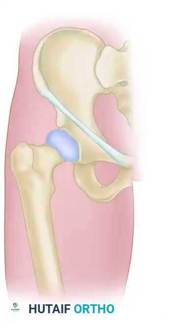
The posterior pelvic ring is the primary weight-bearing axis of the human pelvis, responsible for transferring axial loads from the spine to the lower extremities. Disruptions of this complex—whether through sacroiliac (SI) joint dislocations, fracture-dislocations, or sacral fractures—result from high-energy trauma and demand robust biomechanical stabilization.
Percutaneous iliosacral screw fixation has emerged as the gold standard for stabilizing the posterior pelvic ring. Compared to traditional open posterior approaches, the percutaneous technique significantly reduces surgical site morbidity, minimizes blood loss, and lowers the risk of catastrophic wound infections, particularly in patients with compromised soft tissue envelopes (e.g., Morel-Lavallée lesions). However, this technique is highly technically demanding. It requires an intimate three-dimensional understanding of pelvic osseous anatomy, mastery of fluoroscopic triangulation, and meticulous surgical execution to avoid devastating iatrogenic injuries to the L5 nerve root, S1 nerve root, or the internal iliac neurovascular bundle.
This comprehensive guide details the supine approach to percutaneous iliosacral screw fixation, providing a textbook-level breakdown of indications, preoperative planning, fluoroscopic anatomy, and step-by-step surgical execution.
SURGICAL ANATOMY AND BIOMECHANICS
Understanding the osseous corridors of the upper sacrum is paramount. The S1 and S2 vertebral bodies provide the primary pathways for iliosacral screws.
The S1 Osseous Corridor
The S1 corridor is the most frequently utilized pathway. It is bounded:
* Anteriorly: By the anterior sacral cortex and the internal iliac vessels.
* Superiorly: By the S1 superior endplate and the L5-S1 disc space.
* Inferiorly: By the S1 neuroforamen (containing the S1 nerve root).
* Posteriorly: By the sacral spinal canal.
* Anterosuperiorly: By the sacral ala, over which the L5 nerve root drapes.
Sacral Dysmorphism
Approximately 30-40% of the population exhibits sacral dysmorphism, which drastically alters the safe osseous corridor.
Clinical Pearl: Identifying Sacral Dysmorphism
Preoperative identification of a dysmorphic sacrum is critical. Radiographic hallmarks include:
1. Upper sacral segment elevated above the iliac crests.
2. Collinear alignment of the upper sacral neural foramina.
3. A non-recessed, acute alar slope.
4. A "tongue-in-groove" appearance of the sacroiliac joint on the outlet view.
5. Residual vestigial disc spaces between S1 and S2.
In dysmorphic pelves, the S1 corridor is often oblique and narrow, necessitating an oblique screw trajectory or reliance on the S2 corridor, which is typically more capacious in these patients.
PREOPERATIVE PLANNING
Standard anteroposterior (AP), inlet, and outlet radiographs of the pelvis are mandatory. However, plain radiography is insufficient for preoperative planning.
A fine-cut (1-2 mm) computed tomography (CT) scan with multiplanar reconstructions (axial, coronal, and sagittal) is the absolute standard of care. The CT scan allows the surgeon to:
* Assess the exact morphology of the sacral fracture or SI joint disruption.
* Evaluate the presence of sacral dysmorphism.
* Measure the width and angle of the S1 and S2 safe zones.
* Determine the optimal screw length and diameter (typically 7.0 mm or 7.3 mm cannulated screws).
PATIENT POSITIONING AND OPERATING ROOM SETUP
The supine position is highly advantageous for percutaneous iliosacral screw fixation. It allows for simultaneous management of anterior pelvic ring injuries, facilitates excellent airway access for the anesthesia team, and simplifies fluoroscopic positioning.
Positioning Steps
- Table Selection: Position the patient supine on a completely radiolucent Jackson table or a flat radiolucent trauma table.
- Lumbosacral Bump: Place a soft, radiolucent support (bump) underneath the lumbosacral spine. This elevates the patient's pelvis slightly off the table, ensuring that the C-arm can achieve a steep outlet view without the image intensifier colliding with the table base.
- Arm Positioning: Secure the patient's arms across the chest or place them on arm boards positioned superiorly to prevent interference with the C-arm.
- C-Arm Placement: Position the C-arm fluoroscopy unit on the side opposite the injured hemipelvis. The monitor should be placed in the surgeon's direct line of sight.
THE FLUOROSCOPIC "HOLY TRINITY"
Safe percutaneous fixation relies entirely on the surgeon's ability to interpret three distinct fluoroscopic views. Before prepping and draping, the surgeon must obtain and save these views to ensure adequate visualization.
1. The Inlet View
- Angle: The C-arm is tilted approximately 25° to 30° caudad.
- Purpose: Assesses anterior-to-posterior translation of the pelvic ring.
- Safety Check: Visualizes the anterior sacral cortex (preventing vascular injury) and the anterior border of the spinal canal (preventing central neurologic injury).
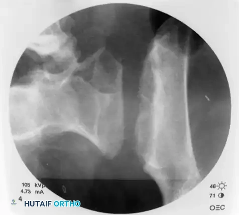
2. The Outlet View
- Angle: The C-arm is tilted approximately 40° to 45° cephalad (aiming perpendicular to the anterior sacral body).
- Purpose: Assesses superior-to-inferior (vertical) translation.
- Safety Check: Visualizes the S1 superior endplate and the S1 neuroforamina. This view ensures the screw does not violate the L5-S1 disc space or the S1 nerve root.
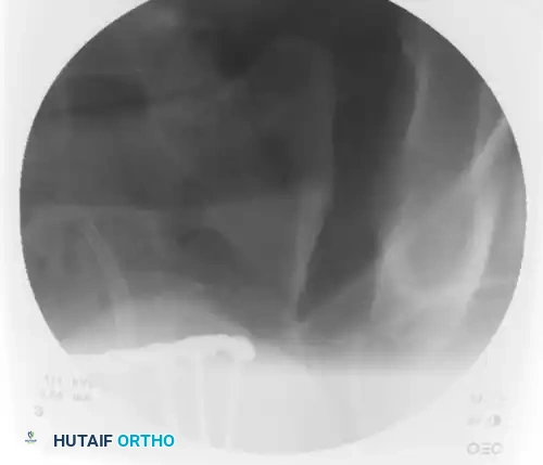
3. The Lateral Sacral View
- Angle: A true lateral across the pelvis. The greater sciatic notches and iliac cortical densities must be perfectly superimposed.
- Purpose: Identifies the starting point on the ilium and visualizes the alar slope.
- Safety Check: Ensures the guidewire remains within the safe osseous corridor of the sacral body, avoiding the anterior alar slope where the L5 nerve root resides.
CLOSED REDUCTION TECHNIQUES
Surgical Warning: Fixation vs. Reduction
Percutaneous iliosacral screws are fixation devices, not reduction tools. Attempting to pull a displaced pelvis together with a lag screw will inevitably lead to hardware failure, loss of fixation, or iatrogenic nerve injury due to altered anatomy. The posterior ring must be anatomically reduced prior to guidewire insertion.
Aids for closed reduction include:
* Longitudinal Traction: Applied via a distal femoral skeletal traction pin to correct vertical shear displacement.
* Internal Rotation: To close an "open book" (APC) injury.
* Schanz Pins: Placement of 5.0 mm Schanz pins into the iliac wings to act as "joysticks" for manipulation.
* Anterior Fixation: Prior application of an anterior external fixator or anterior symphyseal plate can stabilize the anterior ring, acting as a hinge to facilitate posterior reduction.
SURGICAL TECHNIQUE: STEP-BY-STEP EXECUTION
Once anatomic reduction is confirmed fluoroscopically, the percutaneous fixation begins.
Step 1: Identifying the Starting Point
On the true lateral sacral fluoroscopic view, identify the anterior and posterior portals of the first sacral segment (S1). The exact starting point on the ilium depends entirely on the pathology being treated:
- Sacral Fractures: Require a trajectory that is strictly transverse to the patient's body. This allows the screw to cross the fracture orthogonally, providing compression without inducing shear forces.
- Sacroiliac Dislocations: Require a trajectory that travels from posteroinferior to anterior proximal. The screw must be placed perpendicular to the plane of the sacroiliac joint to maximize biomechanical stability.
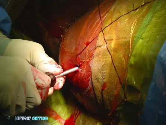
Step 2: Incision and Guide Placement
Mark the ideal starting point on the skin based on the lateral fluoroscopic projection. Make a precise 1-cm stab incision through the skin and fascia.
Advance a cannulated guide assembly (consisting of an outer sleeve and a sharp inner trocar) through the gluteal musculature down to the outer table of the ilium.
On the lateral fluoroscopic view, place the tip of the guide on the exact predetermined starting spot. Once positioned correctly, impact the guide firmly into the iliac cortex using a mallet. This creates a stable docking point and prevents the guide from skiving along the curved iliac wing.
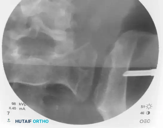
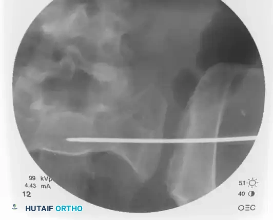
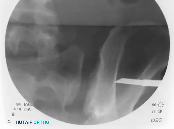
Step 3: Trajectory Adjustment and Guidewire Insertion
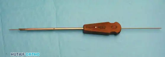
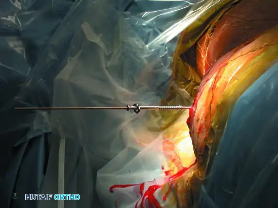
Remove the inner trocar, leaving the cannulated sleeve docked in the bone. Insert a threaded 2.8 mm or 3.2 mm guidewire into the sleeve.
Utilizing biplanar fluoroscopic imagery—rapidly alternating between the inlet and outlet views—adjust the trajectory of the guide sleeve to safely target the center of the S1 vertebral body.
- On the Inlet View: Aim for the center of the sacral body, staying well posterior to the anterior sacral cortex and anterior to the spinal canal.
- On the Outlet View: Aim between the S1 superior endplate and the S1 neuroforamen.
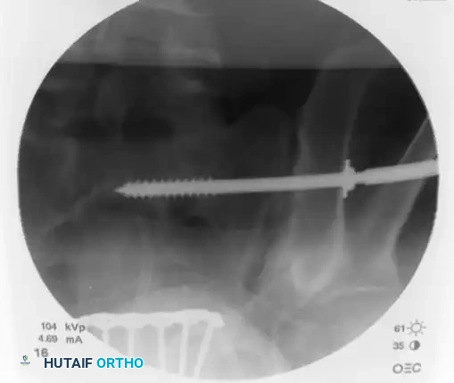
Once the trajectory is perfected, advance the guidewire under power across the sacroiliac joint and into the sacral ala.
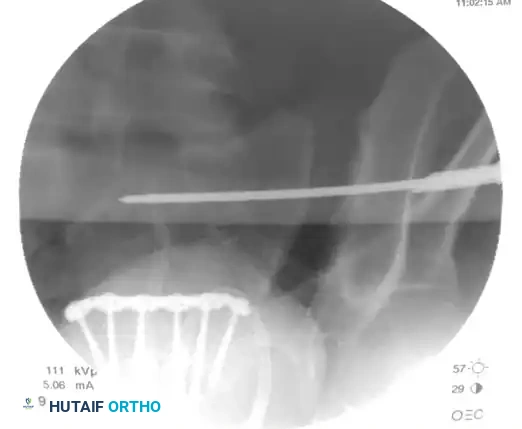
Stop advancing just before the midline. Confirm safe passage on both the inlet and outlet views.
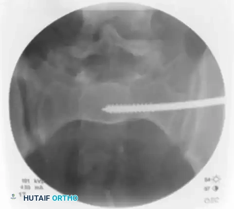
Finally, check the lateral sacral view to ensure that the guidewire is entirely contained within the osseous boundaries of the sacral body and has not breached the anterior alar slope.
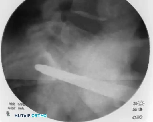
Step 4: Drilling and Measurement
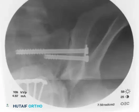
With the guidewire safely positioned in the S1 body (or extending into the contralateral S1 body if a trans-sacral screw is planned), measure the required screw length using a cannulated depth gauge.
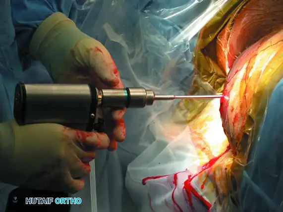
Advance the appropriate cannulated drill bit over the guidewire. Drill through the outer iliac cortex and across the sacroiliac joint. In young patients with dense bone, drilling into the sacral body may be necessary; in osteoporotic patients, drilling only the lateral iliac cortex is often sufficient to prevent stripping the sacral cancellous bone.
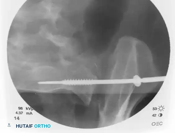
Step 5: Screw Insertion
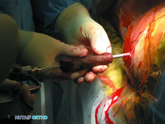
Select a cannulated, partially threaded cancellous screw (if compression across an SI joint or sacral fracture is desired) or a fully threaded screw (if acting purely as a position screw to prevent over-compression of a comminuted sacral fracture). Add a washer to prevent the screw head from sinking into the thin iliac cortex.
Advance the screw over the guidewire using a cannulated screwdriver.
As the screw crosses the SI joint, continuously check its position on the inlet and outlet views to ensure the guidewire does not inadvertently advance and breach the anterior sacral cortex or spinal canal.
Once the screw is fully seated, perform a final fluoroscopic confirmation on the anteroposterior, inlet, and outlet views. The screw threads should have excellent purchase in the dense bone of the sacral body, and the fracture/dislocation should be anatomically reduced and compressed.
ADJUNCTIVE TECHNIQUES: ANTERIOR APPROACH AND STABILIZATION
While percutaneous posterior fixation is the workhorse of pelvic trauma, certain injury patterns—such as highly unstable crescent fractures or chronic SI joint disruptions—may require direct open reduction and internal fixation via an anterior approach.
Anterior Plating of the Sacroiliac Joint
When an anterior approach is indicated, the patient remains supine. An incision is made along the anterior iliac crest, extending distally toward the anterior superior iliac spine (ASIS). The iliacus muscle is elevated to expose the anterior aspect of the sacroiliac joint.
After direct visualization and reduction of the joint, stabilization is achieved by fixing the sacral ala to the ilium. This is typically performed using two orthogonal, two-hole or three-hole dynamic compression plates (or specialized pelvic reconstruction plates) placed across the anterior SI joint.
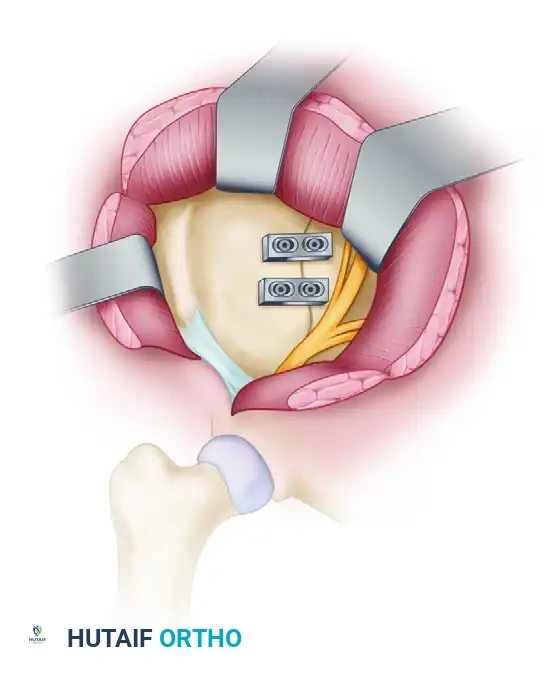
This anterior plating technique provides excellent biomechanical stability against external rotation forces and can be used in conjunction with posterior percutaneous screws for maximal construct rigidity.
POSTOPERATIVE PROTOCOL AND REHABILITATION
The postoperative management of patients undergoing percutaneous iliosacral screw fixation is dictated by the overall injury pattern and the stability of the fixation construct.
- Weight-Bearing Status: Patients are typically restricted to toe-touch weight-bearing (TTWB) or non-weight-bearing (NWB) on the affected extremity for 8 to 12 weeks. Early aggressive weight-bearing can lead to hardware failure, screw back-out, or loss of reduction.
- Deep Vein Thrombosis (DVT) Prophylaxis: Pelvic trauma patients are at an exceptionally high risk for venous thromboembolism. Chemical prophylaxis (e.g., Low Molecular Weight Heparin) should be initiated as soon as it is deemed safe from a hemorrhagic standpoint, typically within 24 hours postoperatively.
- Radiographic Follow-up: AP, inlet, and outlet radiographs should be obtained at 2 weeks, 6 weeks, 12 weeks, and 6 months postoperatively to monitor for maintenance of reduction, hardware integrity, and progressive osseous union.
COMPLICATIONS AND PITFALLS
Despite its minimally invasive nature, percutaneous iliosacral screw fixation carries significant risks if performed without meticulous attention to detail.
- Neurologic Injury: The most feared complication. Misplacement of the screw anteriorly can injure the L5 nerve root. Inferior misplacement violates the S1 foramen, injuring the S1 nerve root. Medial over-penetration can enter the spinal canal. Continuous biplanar fluoroscopy is the only defense against this.
