🎓
Viva Exam
| Principles of limb reconstruction | 427 | Principles of deformity correction | 436 |
|---|---|---|---|
| Surgical techniques | 428 | Innovation in limb lengthening433 | Femoral lengthening434 |
| Tibial lengthening and reconstruction438 | |||
| Viva questions441 | |||
| Principles of limb reconstruction | |||
| When subjected to slow, steady traction, under the appropriate conditions, living tissue becomes metabolically activated and is able to regenerate. This ‘tension-stress’ effect was described by Professor Gavril Abramovich Ilizarov from Kurgan in western Siberia, who pioneered the field of limb reconstruction from the early 1950s and developed the highly successful techniques that are still in use today. | |||
| Callus, formed at a corticotomy site, can be distracted at speeds of up to 1 mm per day and, reliably, form new bone in the process of ‘distraction osteogenesis’. Once the goal length is achieved, a period of consolidation is required before fixator removal. This takes approximately 30–40 days per centimetre of lengthening to prevent bowing or fracture. Anecdotally, the maximum, safe distraction possible per procedure is 20% of the original length of the bone being lengthened. | |||
| Distraction osteogenesis requires | |||
| 1. Stability | |||
| 2. Maintenance of blood supply | |||
| 3. A latency period (5–7 days) | |||
| 4. Appropriate rate of distraction (0.75–1 mm per day) | |||
| 5. Appropriate rhythm (frequency) of distraction (0.25 mm, 6–8 hourly) | |||
| Biomechanics | |||
| 6. Monolateral rail | |||
| 1. Cantilever loading | |||
| 2. Concentrated high stress on near cortex | |||
| 7. Circular frame | |||
| 1. Beam loading | |||
| 2. More even distribution of stress across cortices | |||
| Use of all-wire fixation across a diaphysis is less attractive, due to risks to soft tissues. Hence, hybrid fixation with half-pins and wires is preferred. | |||
| Methods to improve stability | |||
| 8. Wire | |||
| 1. Increase diameter (1.8 mm for adult, 1.5 mm for child) | |||
| 2. Increase tension (130 Nm for adult, 110 Nm for child) | |||
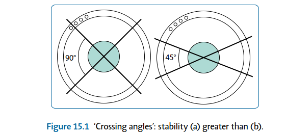
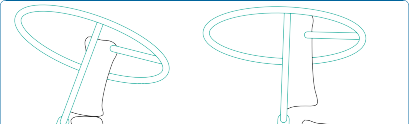
| 3. Increase crossing angles (Figure 15.1) 4. Opposing ‘olive’ wires | |||
| 5. Increase number of wires | |||
| 9. Half-pin | |||
| 1. Increase diameter | |||
| 2. Hydroxyapatite coating | |||
| 3. Increase crossing angles (multiplanar) | |||
| 4. Decrease distance of external construct to bone | |||
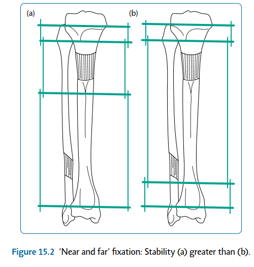
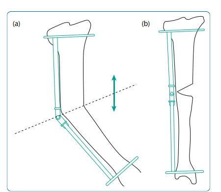
| 5. Near and far positions (Figure 15.2) 6. Increase number | |||
| 10. Ring | |||
| 1. Decrease diameter (Note: Allow at least 2 cm clearance for swelling) | |||
| 2. Fix bone in middle (compromise with eccentrically positioned tibia) | |||
| 3. Near and far positions | |||
| 4. Increase number (including ‘dummy’ rings) | |||
| 11. Attachments | |||
| 1. Use ‘slotted’ bolts – high surface area of contact with wire | |||
| 2. Build ring to wire, if necessary – decrease bend on wire | |||
 🔍 Click to enlarge |
|||
| Figure 15.1 ‘Crossing angles’: stability (a) greater than (b). | |||
| Surgical techniques | |||
| Preoperative planning | |||
| Indications | |||
| 12. Tibial/femoral lengthening | |||
| 13. Long bone deformity correction | |||
 🔍 Click to enlarge |
|||
| Figure 15.2 ‘Near and far’ fixation: Stability (a) greater than (b). | |||
| Contraindications | |||
| 14. Non-compliant patient | |||
| 15. Adjacent joint instability | |||
| 16. Skin infection | |||
| 17. Significant soft tissue contractures | |||
| 18. Poor vascularity | |||
| 19. Pregnancy | |||
| 20. Smoker – relative | |||
| Consent and risks | |||
| 1. Duration of treatment must be emphasised (c. 40 days/cm) | |||
| 2. Pain: Post-surgical, chronic dull ache during distraction is common | |||
| 3. Pin site problems: Inflammation, soft tissue infection, osteomyelitis | |||
| 4. Joint stiffness or subluxation | |||
| 5. Soft tissue contractures | |||
| 6. Vascular injury | |||
| 7. Neurological injury: Perioperative; postoperative stretching | |||
| 8. Premature/delayed/non-union | |||
| 9. Hardware failure | |||
| 10. Late bowing | |||
| 11. Fracture | |||
| 12. Deep vein thrombosis/pulmonary embolism | |||
| Operative planning | |||
| Recent radiographs must be available. These should include full leg length views, in the anteroposterior plane, of both lower limbs with the patellae facing forwards and appropriate lateral views. The mechanical and anatomical axes need to be assessed on both legs. If both legs are ‘abnormal’, standard angles are used for calculations. | |||
| Leg length discrepancy | |||
| Assessment is made from history, examination and radiological findings. Care must be taken to differentiate true from apparent causes of leg length discrepancy. | |||
| Common causes of apparent leg length discrepancy | |||
| 1. Scoliosis | |||
| 2. Hip instability or dislocation | |||
| 3. Fixed hip adduction | |||
| 4. Fixed knee flexion | |||
| 5. Equinus deformity of the ankle | |||
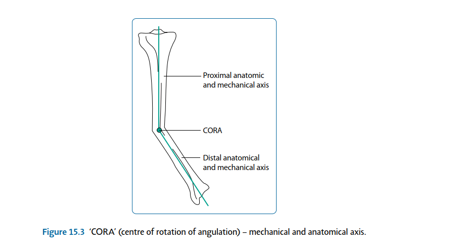
| Angular deformity Clinical and radiographical examination allows calculation of the centre of rotation of angulation (CORA;Figure 15.3). This is present at the intersection point of proximal and distal anatomical axes. A decision is made as to whether the deformity requires surgical correction. This is based on the severity of deformity and the presence or absence of associated factors. | |||
 🔍 Click to enlarge |
|||
| Figure 15.3 ‘CORA’ (centre of rotation of angulation) – mechanical and anatomical axis. | |||
| Indications for surgical correction of angular deformity | |||
| 1. Mechanical axis deviation (MAD) (Figure 15.4) 2. Rotational malalignment | |||
| 3. Translation | |||
| 4. Leg length discrepancy | |||
 🔍 Click to enlarge |
|||
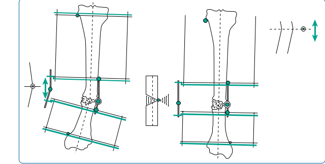
| Figure 15.4 Mechanical axis deviation (MAD). The next decision is the appropriate site for osteotomy. Osteotomy performed at the CORA will not result in translation (Figure 15.5); osteotomy away from the CORA will produce translation. Note: If the hinge is not on the bisector line (Figure 15.6) or the CORA is not on the anatomical axis, osteotomy at any level will result in translation. Surgical technique | |||
| Wire insertion | |||
| 21. Aseptic ‘no hands’/‘Russian’ technique | |||
| 22. Alcohol-soaked gauze used to coat and hold wire | |||
| 23. Low heat generation is ensured via short, intermittent bursts with the wire driver | |||
| 24. Wire tapped with mallet, when through contralateral skin | |||
| Half-pin insertion | |||
| 25. Stab skin incision | |||
| 26. Blunt dissection to bone | |||
 🔍 Click to enlarge |
|||
 🔍 Click to enlarge |
|||
 🔍 Click to enlarge |
|||
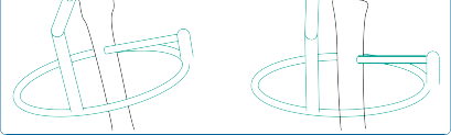
| Figure 15.6 With the hinge placed off the ‘bisector line of the CORA’, translation will result. | |||
| 27. Soft tissue protecting drill guide | |||
| 28. Both cortices pre-drilled | |||
| 29. Low heat generation – intermittent drilling | |||
| 30. Saline to cool and wash out swarf (decreases infection risk) | |||
| Wire/half-pin placement | |||
| 31. ‘Safe corridors’ – avoid neurovascular structures | |||
| 32. Avoid crossing compartments, if possible | |||
| 33. Soft tissues on stretch, e.g. quadriceps in flexion, hamstrings in extension (helps postoperative mobility) | |||
| Corticotomy | |||
| 34. Low energy. | |||
| 35. Minimal incision, to admit osteotome. | |||
| 36. Periosteum incised and preserved, when possible. | |||
| 37. A row of holes are pre-drilled with a 4.8 mm drill, with saline used for cooling. This technique allows low heat generation, reducing corticotomy site bone necrosis. | |||
| 38. An osteotome is used to join holes, with a twist to break the posterior cortex. | |||
| Note: Latent period: 5–7 days; quarter turns: three to four times per day (0.75–1 mm/day). | |||
| Femoral lengthening | |||
| Preoperative planning | |||
| See ‘Principles of limb reconstruction’ (p. 427). | |||
| Surgical technique Corticotomy Landmarks | |||
| Junction of the proximal metaphysis and diaphysis – 1.5 cm distal to lesser trochanter. | |||
| Incision and dissection | |||
| 39. Image intensifier control | |||
| 40. Adequate longitudinal incision (to admit 8 mm osteotome) | |||
| Either | |||
| 41. Anterior approach : Between sartorius and tensor fascia lata (TFL), then through vastus intermedius and rectus femoris | |||
| Or | |||
| 42. Lateral approach : Through TFL and split vastus lateralis Corticotomy technique as earlier. | |||
| Procedure | |||
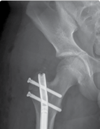
| 43. Monolateral rail (Figure 15.7) 1. If no risk of joint subluxation | |||
| 2. Three half-pins proximal and, at least, three distal to corticotomy | |||
| 44. Circular frame | |||
| 1. If risk of joint subluxation | |||
| 2. Span knee/pelvis | |||
| 3. Arches/two-thirds rings to allow mobility | |||
| 4. Same principles as earlier | |||
 🔍 Click to enlarge |
|||
 🔍 Click to enlarge |
|||
 🔍 Click to enlarge |
|||
 🔍 Click to enlarge |
|||
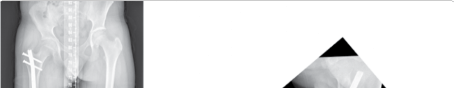
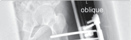
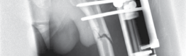
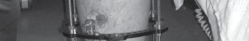
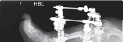
| Figure 15.7 Radiograph of femoral limb reconstruction system (LRS) rail. | |||
| Tibial lengthening | |||
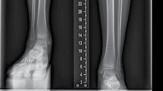
| Preoperative planning See ‘Principles of limb reconstruction’ (p. 427) (Figure 15.8). Surgical technique Corticotomy Landmarks | |||
| Junction of the proximal metaphysis and diaphysis, c.1.5 cm distal to tibial tuberosity. | |||
| Incision and dissection | |||
| 45. Image intensifier control | |||
| 46. Adequate longitudinal incision over anterior tibial crest (to admit 8 mm osteotome) | |||
| 47. Periosteum incised, then lifted off medially and laterally with blunt dissection | |||
| 48. Corticotomy technique as earlier | |||
| Procedure | |||
| 49. Two rings per bone segment (near and far) | |||
| 50. Two wires/half-pins per ring | |||
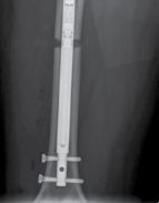
| 51. Four connecting, threaded rods between rings (Figure 15.9) 52. Fibular osteotomy | |||
| 1. Mid-diaphyseal avoids neurovascular structures | |||
| 53. Fix fibula (proximal and distal), to avoid joint subluxation | |||
 🔍 Click to enlarge |
|||
 🔍 Click to enlarge |
|||
 🔍 Click to enlarge |
|||
 🔍 Click to enlarge |
|||
 🔍 Click to enlarge |
|||
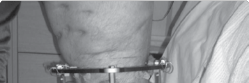
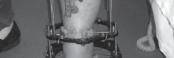
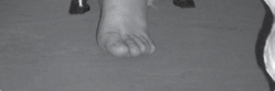
| Figure 15.8 Tibial Ilizarov frame for lengthening. | |||
 🔍 Click to enlarge |
|||
 🔍 Click to enlarge |
|||
 🔍 Click to enlarge |
|||
 🔍 Click to enlarge |
|||
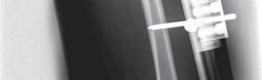
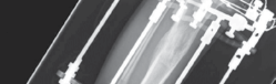
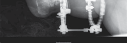
| Figure 15.9 Radiograph of tibial Ilizarov frame for lengthening. | |||
| Principles of deformity correction | |||
| Preoperative planning | |||
| Operative planning | |||
| The initial decision is between acute and gradual correction of the deformity: | |||
| 54. Acute | |||
| 1. Mild deformity | |||
| 2. Opening or closing wedge | |||
| 3. Plate and screws | |||
| 4. Intramedullary (IM) nail | |||
| 5. External fixation | |||
| 55. Gradual | |||
| 1. More severe deformity | |||
| 2. Less risk of neurological damage | |||
| 3. Potential for revision of correction protocol | |||
| 4. Distraction osteogenesis | |||
| 5. Circular frame, e.g. Ilizarov or hexapod type (e.g. Taylor spatial frame [TSF]) | |||
| 6. Monolateral fixator: On convex side – distraction at osteotomy site (seeFigure 15.5); on concave side – compression at osteotomy site therefore requires wedge excision Surgical technique | |||
| Example: Simple, tibial diaphyseal deformity correction with a circular frame. | |||
| 56. Application of proximal and distal rings (see earlier;Figure 15.10) 57. Osteotomy at CORA (see earlier) | |||
| 58. Ilizarov method | |||
| 1. Inter-ring connections with hinges along bisector line of CORA (Figure 15.11) 59. TSF method (Figures 15.12 and 15.13) 1. Inter-ring connections with six oblique, adjustable struts (‘virtual hinge’) | |||
 🔍 Click to enlarge |
|||
| Figure 15.10 ‘Near and far’ rings with osteotomy at centre of rotation of angulation (CORA), hinge along bisector line. | |||
 🔍 Click to enlarge |
|||
 🔍 Click to enlarge |
|||
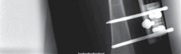
| Figure 15.11 Radiograph of a simple Ilizarov frame construct used to correct deformity in a congenitally short tibia. | |||
 🔍 Click to enlarge |
|||
 🔍 Click to enlarge |
|||
 🔍 Click to enlarge |
|||
| Figure 15.12 Tibial Taylor spatial frame. | |||
 🔍 Click to enlarge |
|||
 🔍 Click to enlarge |
|||
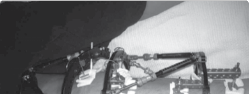
| Figure 15.13 Radiograph of tibial Taylor spatial frame for deformity correction. | |||
| Online computer programme | |||
| 60. Requires: Postoperative radiograph measurements | |||
| 1. Frame measurements (ring sizes/initial strut lengths) | |||
| 61. Delivers: Pre- and post-correction images | |||
| 1. Corrective protocol | |||
| Postoperative care and instructions | |||
| 62. Latency period (5–7 days) | |||
| 63. Gradual correction period | |||
| 64. Consolidation period | |||
| 65. Removal of frame when clinically and radiologically appropriate | |||
| Innovation in limb lengthening and reconstruction | |||
| Complications associated with external fixation during limb reconstruction are common. These include pin-site infection, soft tissue tethering from the pins and wires resulting in pain, regenerate deformity from soft tissue forces or fracture following frame removal and patient intolerance of the frames during treatment. | |||
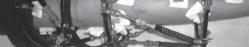
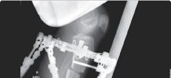
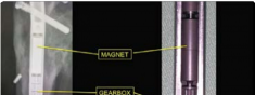
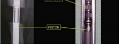
| Surgical techniques have changed in an attempt to minimise these complications. The use of intramedullary implants reduces fixator time and provides regenerate stability. Lengthening over a nail or lengthening followed by nailing still incorporates the use of an external fixator. The development of intramedullary lengthening nails eliminates the need for the external fixator. The initial designs utilised a ratchet mechanism that required rotation of the limb and bone segments to lengthen. A change in design was made where transcutaneous electrical energy drove a motor to improve control in lengthening. The latest and most popular implant is the Precice Intramedullary Lengthening Sysytem (NuVasive Inc., California). This is a magnet-operated telescopic internal lengthening device with an outer casing of titanium alloy (Ti-6Al-4V). A cylindrical rare earth magnet is connected to a gear box and screw shaft assembly within the nail. Two rotating rare earth magnets in an external remote controller (ERC) | |||
 🔍 Click to enlarge |
|||
 🔍 Click to enlarge |
|||
 🔍 Click to enlarge |
|||
 🔍 Click to enlarge |
|||
 🔍 Click to enlarge |
|||
 🔍 Click to enlarge |
|||
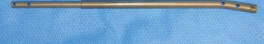
| Figure 15.14 Precice lengthening nail. | |||
 🔍 Click to enlarge |
|||
 🔍 Click to enlarge |
|||
 🔍 Click to enlarge |
|||
 🔍 Click to enlarge |
|||
 🔍 Click to enlarge |
|||
 🔍 Click to enlarge |
|||
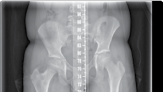
| Figure 15.15 Growth arrest in a 12-year-old child. are held over the magnet within the nail, resulting in rotation of the implant magnet which can either lengthen or shorten the nail with sub-millimeter accuracy. Early results are favourable confirming faster regenerate healing times, less complications, better cosmetic results and more favourable patient outcomes compared to lengthening using an external fixator (Figures 15.14–15.17). | |||
| Recommended |
Scientific References
-
De Bastiani G, Aldegheri R, Renzi-Brivio L et al. Limb lengthening by callus distraction (Callotasis).
_J Pediatr Orthop. 1987;7:129–134._
Cole JD, Justin D, Kasparis T et al. The intramedullary skeletal kinetic distractor (ISKD): First clinical results of a new intramedullary nail for lengthening of the femur and tibia. _Injury_. 2001;32(Suppl 4): SD129–SD139.
Paley D, Herzenberg JE. _Principles of Deformity Correction_. Berlin, Germany: Springer, 2001.
Paley D, Herzenberg JE, Tetsworth K et al. Deformity planning for frontal and sagittal plane corrective osteotomies. _Orthop Clin North Am_. 1994;25:425–465.
Rozbruch SR, Ilizarov S. _Limb Lengthening and Reconstruction Surgery_. New York, NY: Informa, 2007.


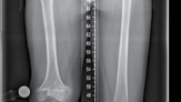
Figure 15.16 Completion of lengthening (8 cm).
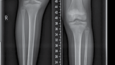
6 weeks post lengthening 3 months post lengthening


Figure 15.17 Consolidation (8 cm).
_[Viva questions_ ](file:///C:/Users/DELL/Desktop/hip/quick%20fact/15.%20Limb%20Reconstruction_Converted.html#bookmark15)
- 1. What are the causes of leg length discrepancy? [View Source / PubMed]
- 2. What problems are associated with leg length discrepancy? [View Source / PubMed]
- 3. How do you assess length discrepancy of the lower limbs? [View Source / PubMed]
- 4. What are the differences between true, apparent and functional leg length discrepancy? [View Source / PubMed]
- 5. What are the treatment options for leg length discrepancy in both adults and children? [View Source / PubMed]
- 6. What are the relative percentage contributions to normal growth of all of the lower limb physes? [View Source / PubMed]
- 7. How can you predict the magnitude of leg length discrepancy at skeletal maturity? [View Source / PubMed]
- 8. What are the problems associated with shoe raises? [View Source / PubMed]
- 9. What problems may occur as a consequence of acute shortening procedures? [View Source / PubMed]
- 10. Who was Professor Gavril Abramovich Ilizarov? [View Source / PubMed]
- 11. What problems may occur due to the leg lengthening procedure? [View Source / PubMed]
- 12. What are the prerequisite factors necessary for successful leg lengthening? [View Source / PubMed]
- 13. What are the reasons for leaving a ‘latency period’ prior to commencing distraction? [View Source / PubMed]
- 14. What are the advantages and disadvantages of lengthening intramedullary nails? [View Source / PubMed]
- 15. Give the causes of lower limb deformity. [View Source / PubMed]
- 16. How do you assess the degree of lower limb deformity? [View Source / PubMed]
- 17. Draw a ‘Selenius graph’. [View Source / PubMed]
- 18. What options are available for correcting lower limb deformity in both adults and children? [View Source / PubMed]
- 19. What are the consequences of hinge misplacement when applying an Ilizarov frame for deformity correction? [View Source / PubMed]
- 20. What are the advantages of using a ‘Taylor spatial frame’ rather than an Ilizarov frame for deformity correction? [View Source / PubMed]
