Introduction to Ilizarov External Fixation
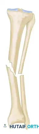
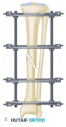
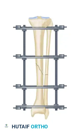
The management of complex, comminuted, or open tibial shaft fractures presents a formidable challenge to the orthopedic surgeon. The Ilizarov external fixation system, pioneered by Professor Gavriil Ilizarov, revolutionized the treatment of these injuries by introducing the concept of the tension-stress effect. Unlike rigid internal fixation, the Ilizarov circular frame utilizes tensioned fine wires to provide exceptional shear and torsional stability while permitting controlled axial micromotion. This unique biomechanical environment stimulates robust secondary bone healing (callus formation) without the need for extensive soft tissue stripping at the fracture site.
This comprehensive guide details the surgical technique for applying an Ilizarov external fixator to tibial shaft fractures, expanding upon foundational operative principles to provide a masterclass in frame assembly, multi-planar fracture reduction, safe-zone wire insertion, and the management of postoperative complications.
Biomechanical Principles and Preoperative Planning
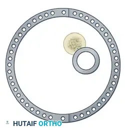
The efficacy of the Ilizarov frame relies on the precise geometric arrangement of rings and tensioned wires. Standard fine wires (1.5 mm to 1.8 mm) are tensioned to 110–130 kg, transforming them from flexible filaments into rigid beams capable of supporting physiological loads.
Preoperative planning is critical. Axial computed tomography (CT) scans are highly recommended to delineate fracture morphology, identify occult comminution, and determine the most appropriate method of fixation.
Surgical Warning: Interfragmentary screws or wires in the diaphyseal region should generally be avoided when using an Ilizarov frame for primary fracture healing. These rigid constructs negate the axial flexibility of the circular fixator, which is the primary driver of secondary osteogenesis. The use of diaphyseal interfragmentary screws in conjunction with circular frames has been strongly associated with delayed union and nonunion.
Patient Positioning and Preparation
Optimal patient positioning is the first critical step in ensuring a smooth surgical workflow.
- Table Setup: Place the patient supine on a radiolucent table extension. This allows for unimpeded, high-quality fluoroscopic imaging in both the anteroposterior (AP) and lateral planes.
- Traction Application: The external fixator itself, or a dedicated traction table, can be used to apply longitudinal traction.
- Reduction Parameters: Longitudinal traction typically reduces most tibial shaft fractures to within 10 to 15 degrees of anatomical alignment. In standard trauma applications, the addition of hinges to the frame is usually unnecessary.
Pitfall: Excessive or prolonged traction must be strictly avoided. Over-distraction places undue tension on the neurovascular bundles, significantly increasing the risk of iatrogenic neurapraxia or vascular compromise.
Surgical Technique: Step-by-Step Application
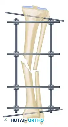
Step 1: Frame Preparation and Initial Placement
The Ilizarov frame is typically preassembled prior to the induction of anesthesia, based on preoperative measurements of the patient's limb.
- After meticulously preparing and draping the extremity, disconnect the ring connection bolts on one side of the preassembled frame to open it.
- Place the opened frame around the injured extremity.
- Reassemble the frame, ensuring adequate soft tissue clearance circumferentially. A general rule is to maintain at least two fingerbreadths (approximately 2 to 3 cm) of clearance between the skin and the inner border of the rings to accommodate postoperative edema.
- Align the frame so that the longitudinal coupling bolts are parallel to the anterior crest of the tibia in both the AP and lateral planes.
Step 2: Reference Wire Placement and Frame Suspension
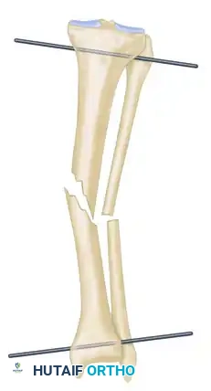
To establish the foundational alignment of the construct, proximal and distal reference wires must be placed accurately.
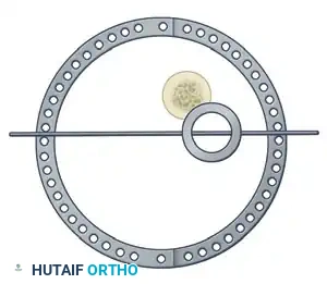
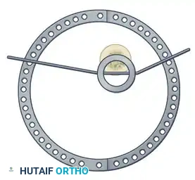
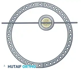
- Hold the frame in the desired position and insert proximal and distal transverse reference wires. These wires must be placed parallel to the knee joint line (proximal) and the ankle joint line (distal).
- As these reference wires are secured to the frame and tension is applied, initial correction of the fracture in the coronal plane is achieved.
Alternative Suspension Technique:
If manual holding is difficult, suspend the frame using ordinary surgical suction tubing. Place the tubing around the extremity and secure it to the frame with towel clips.
- Eccentrically tilt the proximal and distal rings until they are perfectly parallel to the knee and ankle joints, respectively.
- After securing fixation with at least two tensioned wires to both the proximal and distal rings, adjust the threaded rods to bring these two rings parallel to their counterparts in the center of the frame. This maneuver facilitates further indirect fracture reduction.
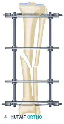
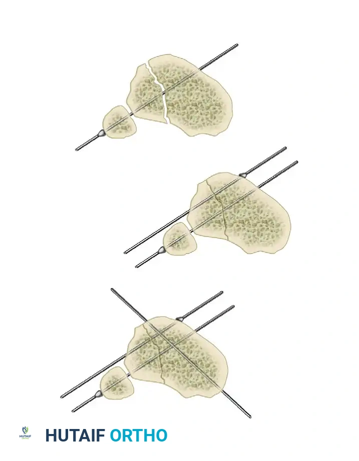
Step 3: Multi-Planar Fracture Reduction Using Olive Wires
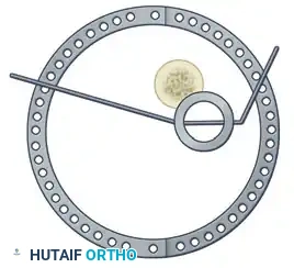
Olive wires (wires with a small metal bead or "olive" forged into them) are powerful tools for translating bone fragments and achieving final reduction.
- Coronal Plane Correction: Use arched olive wires for final fracture reduction. For residual displacement in the coronal plane, place an olive wire in a transverse fashion (ensuring it passes through a safe anatomical zone).
- Apply tension to the wire without securing it tightly to the frame on the opposite side. The tensioner will pull the olive—and consequently the bone fragment—toward the tensioner, correcting the translation.
- Use continuous image intensification to ensure adequate reduction is achieved without over-translating the fragment.
- Once adequate correction is obtained in the coronal plane, secure the wire to the frame on the olive side.
- Sagittal Plane Correction: If further correction is required in the sagittal plane, connect another olive wire in an arched fashion. Tensioning this arched wire will impart a directional force vector to the bone, achieving final sagittal alignment.
Step 4: Eliminating Residual Distraction
Following multi-planar correction, it is imperative to assess the fracture site for any residual longitudinal distraction. Distraction gaps inhibit secondary bone healing and lead to nonunion. Adjust the longitudinal threaded rods to compress the fracture site and eliminate any residual distraction.
Step 5: Managing Specific Fracture Patterns (Opposing Olive Wires vs. Lag Screws)
In rare cases involving specific oblique or spiral fracture patterns, two olive wires can be inserted from opposite sides, perpendicular to the fracture plane. As these wires are tensioned, they effect reduction and apply interfragmentary compression.
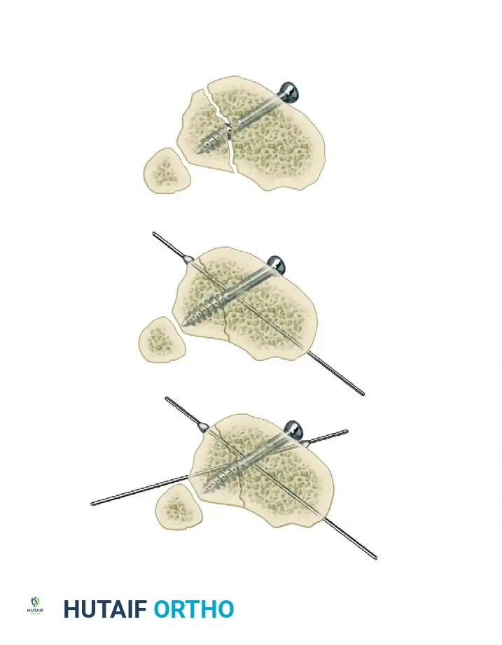
Clinical Pearl: While opposing olive wires can provide excellent compression, this pattern of wire placement may not always be anatomically safe due to the location of neurovascular structures.
If opposing olive wires cannot be placed safely, these specific fracture patterns may be fixed with one or more lag screws, followed by the application of the external fixator to neutralize bending and torsional forces. However, as previously warned, this should be reserved for specific metaphyseal or highly stable configurations, avoiding diaphyseal interfragmentary fixation when possible.
Safe Transfixation Wire Insertion Protocol
The insertion of fine wires must be executed with meticulous care to avoid thermal necrosis of the bone and injury to soft tissues.
- Wire Selection: In general, 1.5-mm and 1.8-mm wires require no skin incision or drill sheath. If larger 2.0-mm wires are utilized, a small stab incision and a protective drill sheath are mandatory.
- Handling: Glove paper can be used to grasp the wire close to the insertion site, providing increased control and preventing the wire from wandering off the cortical surface.
- Insertion Technique: Predrilling is not required for fine wire insertion.
- Determine the safe angle for transfixation at the given anatomical level (referencing standard cross-sectional anatomy atlases to avoid the anterior tibial artery, common peroneal nerve, and posterior tibial neurovascular bundle).
- Stab the wire directly through the skin and muscle down to the bone.
- Use a low-speed power drill with frequent pauses, or a hand drill, to advance the wire across both cortices. High-speed drilling generates excessive heat, leading to ring sequestrum and premature pin loosening.
- Soft Tissue Protection: When the wire emerges from the far cortex, immediately stop drilling. Tap the wire through the remaining soft tissues with a mallet. This blunt passage significantly reduces the risk of wrapping or lacerating neurovascular structures.
- Frame Attachment: Attach the wires to the rings without bending them to meet the frame. Bending wires introduces asymmetric tension and weakens the construct. If a wire does not sit flush against the ring, use small washers or spacers to build the connecting bolts off the frame to meet the wire in its natural trajectory.
- Skin Interface: Ensure there is no undue pressure or tension on the pin-skin interface. Release any tethered skin with a small scalpel incision to prevent necrosis.
Postoperative Management and Complications
Neurovascular Injury
With careful adherence to anatomical safe zones, acute neurovascular injury from transfixation wires is rare.
- Acute Phase: In the immediate postoperative period, if a patient reports unusually severe, radiating pain along a specific wire, it must be suspected of passing through or impinging upon a nerve. The offending wire should be removed immediately.
- Late Phase: Late neurovascular injury is exceedingly rare during simple fracture immobilization, though it may occur during bone transport procedures due to the relative motion of fragments.
Joint Contractures
Flexion contractures of the knee and equinus contractures of the ankle are common pitfalls. They occur less frequently in static fracture treatment compared to limb lengthening but must be actively prevented.
- Prevention: Institute immediate, aggressive active range-of-motion exercises. Early weight-bearing in the frame is highly encouraged, as it not only prevents contractures but also stimulates fracture healing via axial micromotion.
Pin Track Infections
Pin irritation is ubiquitous, but deep, serious pin track infections leading to osteomyelitis are unusual if managed proactively.
- Daily Care: Wire-skin interfaces should be cleaned daily with mild soap and water.
- Hygiene: After the initial surgical wounds have healed, patients are encouraged to take normal showers. Swimming in chlorinated pools is permissible, provided it is followed by a clear water rinse.
- Dressings: Gentle pressure dressings using sponges or gauze help prevent pistoning motion between the pin and the skin, which is the primary catalyst for infection.
- Management: A loose wire must be suspected at the first sign of localized pain and inflammation. Suspect wires should be re-tensioned. Generalized cellulitis is managed by assessing all pin sites and administering targeted oral antibiotics. If a pin track infection fails to respond to oral antibiotics and local care, the wire must be exchanged or removed.
Soft Tissue Impingement and Edema
Patients with concomitant head injuries or polytrauma may develop excessive dependent edema due to a lack of mobility and diminished lymphatic pumping.
- Late Impingement: If the skin begins to impinge on the frame toward the end of treatment due to swelling, a simple clinical trick can be employed. Thin cardboard can be slotted to accommodate the wires and slipped between the skin and the frame to distribute pressure and prevent focal necrosis.
- Early Impingement: If severe skin impingement occurs early in the treatment course, the frame must be structurally modified.
- Shifting the Frame: If impingement occurs along a short-arc segment of several rings, the entire frame can be shifted away from the impingement by loosening the wire fixation bolts and reattaching them in new holes further away from the skin.
- Ring Modification: If impingement is localized to a single ring, that ring can be modified by introducing two short extension plates between the ends of the half-rings, creating an elliptical shape with its major axis directed toward the swelling. Alternatively, if sufficient stability remains, a segment of the ring can be cut out with a metal saw.
- Frame Expansion: For major, circumferential impingement at multiple levels, a larger frame must be constructed around the original frame. The rings of the new, larger frame are positioned at exactly the same levels. The curled ends of the existing wires are straightened, and the wires are attached to the outer frame. Finally, the wire fixation bolts on the smaller, inner frame are loosened and the inner rings are removed.
