f
 ---
---

 ## DEFINITION
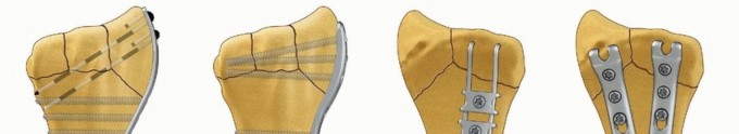
Fragment-specific fixation is a treatment approach for complex articular fracture patterns characterized by independent fixation of each major fracture component with an implant specific for that particular fragment ( FIG 1). Fragment-specific implants are usually low profile and have a certain degree of “spring-like” elasticity; the combination of independent fixation of multiple fragments in different planes can restore articular anatomy without the need for effective thread purchase in small periarticular fragments. Surgical planning is extremely important to determine whether a single approach or a combination of surgical approaches is needed to visualize and fix each of the main fracture components that make up a particular injury. For distal radius fixation, a complete set of implants should be available to address any of the five primary fracture elements: the radial column, ulnar corner, volar rim, dorsal wall, and/or impacted articular fragments. In addition, identification and treatment of distal radioulnar joint (DRUJ) disruption and injuries of the ulnar column should be included.
### FIG 1 • Fragment-specific implants.
As a general rule, this technique avoids creation of large holes in small distal fragments, with fixation based and often triangulated to the stable ipsilateral cortex of the proximal fragment. The goal of fragment-specific fixation is creation of a multiplanar, load-sharing construct that restores an anatomic articular surface with enough stability to initiate motion postoperatively. 2, 7, 11 76
## DEFINITION
Fragment-specific fixation is a treatment approach for complex articular fracture patterns characterized by independent fixation of each major fracture component with an implant specific for that particular fragment ( FIG 1). Fragment-specific implants are usually low profile and have a certain degree of “spring-like” elasticity; the combination of independent fixation of multiple fragments in different planes can restore articular anatomy without the need for effective thread purchase in small periarticular fragments. Surgical planning is extremely important to determine whether a single approach or a combination of surgical approaches is needed to visualize and fix each of the main fracture components that make up a particular injury. For distal radius fixation, a complete set of implants should be available to address any of the five primary fracture elements: the radial column, ulnar corner, volar rim, dorsal wall, and/or impacted articular fragments. In addition, identification and treatment of distal radioulnar joint (DRUJ) disruption and injuries of the ulnar column should be included.
### FIG 1 • Fragment-specific implants.
As a general rule, this technique avoids creation of large holes in small distal fragments, with fixation based and often triangulated to the stable ipsilateral cortex of the proximal fragment. The goal of fragment-specific fixation is creation of a multiplanar, load-sharing construct that restores an anatomic articular surface with enough stability to initiate motion postoperatively. 2, 7, 11 76
 ---
---
 ### FIG 2 • Articular fracture components.
Fragment-Specific Fixation: Restore Carpal Facet Horizon
Updated: Feb 2026
79 Views
Key Medical Takeaway
Your ultimate guide to Fragment-Specific Fixation: Restore Carpal Facet Horizon starts here. The carpal facet horizon describes the crucial articular alignment and smooth surface formed by the distal radius’s scaphoid and lunate facets, articulating with carpal bones. Maintaining this precise horizon is vital for optimal wrist function. Restoring the carpal facet horizon is a key objective in fragment-specific fixation, ensuring anatomic articular surface and stability after complex distal radius fractures.
 ---
---
 ### FIG 3 • Pathogenesis of dorsal radius fractures. A. Dorsal bending. B. Volar bending. C. Dorsal shear. D. Volar shear. E. Radial shear. F. Three-part articular. G. Comminuted articular. H. Carpal avulsion. I. High energy. 78 Dorsal shearing injuries present as fractures of the dorsal rim and are often associated with dorsal instability of the carpus ( FIG 3C). These injuries often have a depressed articular fragment and may have additional radial column involvement. Volar shearing injuries present as displaced fractures of the volar rim and result in volar instability of the carpus ( FIG 3D). This pattern often has multiple articular fragments and is highly unstable. It is not usually amenable to closed methods of treatment. Radial shearing fractures (chauffeur's fracture) are identified by a characteristic transverse fracture line across the radial styloid that extends into the radiocarpal joint. These injuries often have more extensive chondral disruption than may be appreciated from the radiographic findings ( FIG 3E). Simple three-part fractures are usually the result of lowenergy injuries that combine a dorsal bending mechanism with some axial loading across the carpus ( FIG 3F). This pattern is characterized by the presence of an ulnar corner fragment involving the dorsal portion of the sigmoid notch, a main articular fragment, and a proximal shaft fragment. Complex articular fractures are usually the result of axial loading injuries from moderate to high-energy trauma. In addition to articular comminution, this pattern may often generate a significant defect in the metaphyseal cavity or complete disruption of the DRUJ ( FIG 3G). The avulsion/carpal instability pattern is primarily a ligamentous injury of the carpus with associated osseous avulsions of the distal radius. Bone fragments are typically small and very distal ( FIG 3H).
 ---
---
 ### FIG 4 • A. Positioning for standard lateral radiography. B. Standard lateral radiograph. C. Positioning for 10-degree lateral radiography. D. Ten-degree lateral radiograph. Note the improved visualization of the articular surface of the base of the scaphoid facet and the entire lunate facet. Injuries from a high-energy mechanism present as complex comminuted fractures of the articular surface with extension into the radial/ulnar shaft ( FIG 3I). ## IMAGING AND OTHER DIAGNOSTIC STUDIES Posteroanterior (PA), standard lateral ( FIG 4A,B), and 10-degree lateral views are routine views for radiographic evaluation of the distal radius. The 10-degree lateral view (FIG 4C,D) clearly visualizes the ulnar two-thirds of the articular surface from the base of the scaphoid facet through the entire lunate facet. Oblique views may also be helpful for evaluating the injury. The radiographic features of distal radius fractures include the following 8: Carpal facet horizon ( FIG 5A,B). This is the radiodense horizontal landmark that is used to identify the volar and dorsal rim on the PA view. If the articular surface has palmar tilt, the x-ray beam is tangential to the subchondral bone of the volar portion of the lunate facet, with the result that the carpal facet horizon identifies the volar rim. However, if the articular surface has displaced into dorsal tilt, the x-ray beam becomes tangential to the subchondral bone of the dorsal portion of the lunate facet instead, and the carpal facet horizon identifies the dorsal rim (not shown). The carpal facet horizon corresponds to the portion of the articular surface visualized on the 10-degree lateral x-ray projection. Teardrop angle (normal 70 ± 5 degrees; FIG 5C,D). The teardrop angle is used to identify dorsiflexion of the volar 79 rim of the lunate facet. Depression of the teardrop angle to a value less than 45 degrees indicates that the volar rim of the lunate facet has rotated dorsally and impacted into the metaphyseal cavity (axial instability pattern of the volar rim). This may be associated with axial and dorsal subluxation of the carpus. Restoration of the teardrop angle is necessary to correct this type of malreduction.
 ---
---


 ### FIG 5 • A. Carpal facet horizon (
arrows
). Used to differentiate between the volar and dorsal rim on the PA projection. B. Origin of carpal facet horizon. The carpal facet horizon is formed by that part of the articular surface that is parallel to the x-ray beam and depends on whether the articular surface is in volar or dorsal tilt. C. Normal teardrop angle. D. Depressed teardrop angle in this case is caused by axial instability of the volar rim. E. Normal articular congruency. F. Abnormal articular congruency, indicating disruption across the volar and dorsal surfaces of the lunate facet. G. AP interval is the point-to-point distance between the corners of the dorsal and volar rim. H. DRUJ interval. I. Normal lateral carpal alignment. J. Dorsal subluxation of the carpus. Congruency of the articular surface ( FIG 5E,F). The subchondral outline of the articular surface of the distal radius is normally both congruent and concentric with the subchondral outline of the base of the lunate; a uniform joint interval should be present between the radius and lunate along the entire articular surface. When the joint interval between these articular surfaces is not uniform, discontinuity and disruption of the lunate facet has occurred. Anteroposterior (AP) distance (normal: females 18 ± 1 mm, males 20 ± 1 mm; FIG 5G). The AP distance is the point-to-point distance from the dorsal to palmar rim of the lunate facet. It is best evaluated on the 10- degree lateral view. Widening of the AP distance implies discontinuity of the volar and dorsal portion of the lunate facet. 80 DRUJ interval ( FIG 5H). The DRUJ interval measures the degree of apposition between the head of the ulna and the sigmoid notch (normal: 2 mm or less). This parameter is best measured with the forearm in neutral rotation. Significant widening of the DRUJ interval implies disruption of the DRUJ capsule and TFCC. Coronal malalignment of the distal radial fragment is often suggested by widening of the DRUJ interval. Lateral carpal alignment ( FIG 5I,J). On the 10-degree lateral view and with the wrist in neutral position, the rotational center of the capitate normally aligns with a line extended from the volar surface of the radial shaft. Dorsal rotation of the volar rim results in a dorsal shift of lateral carpal alignment as the carpus subluxes dorsally. This may place the flexor tendons at a mechanical disadvantage, affecting grip strength. In addition to injury films, reassessing radiographs after reduction can be very helpful in determining the personality and specific components of a particular fracture. Computed tomography (CT) scans allow higher resolution and definition of fracture characteristics, particularly for highly comminuted fractures. Preferably, an attempt at closed reduction before obtaining a CT scan will help limit distortion of the image. CT scans are particularly helpful for visualizing intra-articular fragments as well as DRUJ disruption and incongruity of the sigmoid notch. Clinical evaluation of the carpus, interosseous membrane, and elbow, combined with radiographic studies when needed, should be included to identify the presence of other injuries that may affect the decision for a particular treatment. ## SURGICAL MANAGEMENT
### FIG 5 • A. Carpal facet horizon (
arrows
). Used to differentiate between the volar and dorsal rim on the PA projection. B. Origin of carpal facet horizon. The carpal facet horizon is formed by that part of the articular surface that is parallel to the x-ray beam and depends on whether the articular surface is in volar or dorsal tilt. C. Normal teardrop angle. D. Depressed teardrop angle in this case is caused by axial instability of the volar rim. E. Normal articular congruency. F. Abnormal articular congruency, indicating disruption across the volar and dorsal surfaces of the lunate facet. G. AP interval is the point-to-point distance between the corners of the dorsal and volar rim. H. DRUJ interval. I. Normal lateral carpal alignment. J. Dorsal subluxation of the carpus. Congruency of the articular surface ( FIG 5E,F). The subchondral outline of the articular surface of the distal radius is normally both congruent and concentric with the subchondral outline of the base of the lunate; a uniform joint interval should be present between the radius and lunate along the entire articular surface. When the joint interval between these articular surfaces is not uniform, discontinuity and disruption of the lunate facet has occurred. Anteroposterior (AP) distance (normal: females 18 ± 1 mm, males 20 ± 1 mm; FIG 5G). The AP distance is the point-to-point distance from the dorsal to palmar rim of the lunate facet. It is best evaluated on the 10- degree lateral view. Widening of the AP distance implies discontinuity of the volar and dorsal portion of the lunate facet. 80 DRUJ interval ( FIG 5H). The DRUJ interval measures the degree of apposition between the head of the ulna and the sigmoid notch (normal: 2 mm or less). This parameter is best measured with the forearm in neutral rotation. Significant widening of the DRUJ interval implies disruption of the DRUJ capsule and TFCC. Coronal malalignment of the distal radial fragment is often suggested by widening of the DRUJ interval. Lateral carpal alignment ( FIG 5I,J). On the 10-degree lateral view and with the wrist in neutral position, the rotational center of the capitate normally aligns with a line extended from the volar surface of the radial shaft. Dorsal rotation of the volar rim results in a dorsal shift of lateral carpal alignment as the carpus subluxes dorsally. This may place the flexor tendons at a mechanical disadvantage, affecting grip strength. In addition to injury films, reassessing radiographs after reduction can be very helpful in determining the personality and specific components of a particular fracture. Computed tomography (CT) scans allow higher resolution and definition of fracture characteristics, particularly for highly comminuted fractures. Preferably, an attempt at closed reduction before obtaining a CT scan will help limit distortion of the image. CT scans are particularly helpful for visualizing intra-articular fragments as well as DRUJ disruption and incongruity of the sigmoid notch. Clinical evaluation of the carpus, interosseous membrane, and elbow, combined with radiographic studies when needed, should be included to identify the presence of other injuries that may affect the decision for a particular treatment. ## SURGICAL MANAGEMENT
 ---
---
 ## TECHNIQUES

Keywords